one key安装系统使用说明
安装系统不求人菜鸟Ghost安装全攻略(虚拟光驱、ONEKEY、Ghost32)

安装系统不求人菜鸟Ghost安装全攻略(虚拟光驱、ONEKEY、Ghost32)2008年04月03日星期四下午 01:18Ghost技术发展到现在已经非常成熟了,随着DVD版本的Ghost系统的出现,可以说给Ghost系统插上了腾飞的翅膀!在双核处理器、1GB内存成为标配,即使是最普通的整合主板,运行一个未经任何删简的完整的XP系统都是绰绰有余的。
并且运行速度与精简版系统相比毫不逊色,其稳定性则是精简版系统无法比拟的。
可以预见随着SP3的发布,将来必然是DVD版系统的天下。
作为普通电脑用户来讲,下载个系统直接硬盘安装就可以了,没有必要再去刻盘安装,专业维护人员则更不需要刻盘了。
因此掌握Ghost安装技术实在是省钱、省时、省心的好事情!系统安装前的准备工作:有备方能做到无患!首先要准备一张带有PE 和一键Ghost11的光盘(版本要新,如果没有优盘PE的更要准备一张,以后很多地方要用它!)。
安装前最好能用一键Ghost11做个备份,一键Ghost11的备份文件默认隐藏保存在磁盘的最后一个分区,一般不容易损坏。
一旦系统安装失败,可以启动光盘版的一键Ghost11,它会自动寻找到系统备份文件快速恢复系统。
这样会省很多事的!现在Ghost安装方法主要有:一.解压ISO,运行系统自带的硬盘安装器(AUTORE)直接安装系统二.虚拟光驱加载ISO直接安装系统(这里以Virtual Drive Manager 虚拟光驱为例)附:Virtual Drive Manager虚拟光驱.rar 优点:安装方法简单容易操作。
缺点:与硬盘安装器相同。
三.使用OneKey_2.0安装系统优点:使用方法简单容易操作缺点:同上。
今天就写这些了,其他方法有时间会补上(PE、Ghost32)等。
本人也是菜鸟,在雨林学了不少东西,在此向各位老大表示感谢!本人才疏学浅,写的不好,还望大家多多包涵!以上三种方法是硬盘安装法中最基本,最简单的方法,其共同特点是:操作简便容易上手。
OneKey Ghost Y6.3 四周年纪念版使用方法

网管利器:雨林木风OneKey Ghost Y6.3 四周年纪念版使用方法(图)电脑知识2009-12-24 22:18:48 阅读1174 评论0 字号:大中小订阅网管利器:雨林木风OneKey Ghost Y6.3 四周年纪念版使用方法(图)现在大多数人都会选择安装Ghost系统,省时省力,方便快捷,通常我们会对自己的系统进行一次备份,当日后系统出现故障时可以快速地将系统恢复到备份时的正常状态,这种方法受到大多数电脑用户的欢迎。
而进行系统备份还原需要使用工具进行,系统备份还原工具数量众多,其中不乏精品之作,比较著名的有一键Ghost、一键还原精灵等,今天小编为大家推荐一款来自雨林木风的优秀工具:OneKey Ghost!点击此处下载雨林木风OneKey Ghost Y6.3 四周年纪念版一、雨林木风OneKey Ghost Y6.3 四周年纪念版程序简介:OneKey Ghost是雨林木风出品的一款专业系统备份还原工具,无需安装,绿色环保,并且操作非常简便,可以帮助用户在Windows 环境下对任意分区进行一键备份还原操作。
OneKey Ghost支持多硬盘、混合硬盘(IDE/SATA/SCSI)、混合分区(FAT32/NTFS)、未指派盘符分区、盘符错乱、隐藏分区以及交错存在非Windows 分区。
支持多系统,并且系统不在第一个硬盘第一个分区,完美支持品牌机隐藏分区!二、雨林木风OneKey Ghost Y6.3 四周年纪念版程序资料:三、雨林木风OneKey Ghost Y6.3 四周年纪念版详细说明:1.默认核心是Ghost11.0.1,支持用户自定义Ghost版本;2.程序默认对当前系统所在分区进行备份、还原操作,支持用户选择其他分区;3.纯绿色,不会给系统留下任何临时文件;4.备份时可选压缩方式、默认为快速压缩;5.可根据条件搜索硬盘已存在的映像文件;6.还原时可忽略Ghost映像文件CRC校验;7.可使用本程序取消之前的操作;8.程序人性化的设计,使用更简便、避免操作错误。
克隆软件Ghost初级使用教程

克隆软件Ghost初级使用教程一、什么是Ghost?Ghost(幽灵)软件是美国赛门铁克公司推出的一款出色的硬盘备份还原工具,可以实现FAT16、FAT32、NTFS、OS2等多种硬盘分区格式的分区及硬盘的备份还原。
俗称克隆软件。
1、特点:既然称之为克隆软件,说明其Ghost的备份还原是以硬盘的扇区为单位进行的,也就是说可以将一个硬盘上的物理信息完整复制,而不仅仅是数据的简单复制;克隆人只能克隆躯体,但这个Ghost却能克隆系统中所有的东东,包括声音动画图像,连磁盘碎片都可以帮你复制,比克隆人还厉害哟:)。
Ghost支持将分区或硬盘直接备份到一个扩展名为.gho的文件里(赛门铁克把这种文件称为镜像文件),也支持直接备份到另一个分区或硬盘里。
2、运行ghost:至今为止,ghost只支持Dos的运行环境,这不能说不是一种遗憾:(。
我们通常把ghost文件复制到启动软盘(U盘)里,也可将其刻录进启动光盘,用启动盘进入Dos环境后,在提示符下输入ghost,回车即可运行ghost,首先出现的是关于界面,如图1:图1按任意键进入ghost操作界面,出现ghost菜单。
主菜单共有4项,从下至上分别为Quit(退出)、Options(选项)、Peer to Peer(点对对,主要用于网络中)、Local(本地)。
一般情况下我们只用到Local菜单项,其下有三个子项:Disk(硬盘备份与还原)、Partition(磁盘分区备份与还原)、Check(硬盘检测),前两项功能是我们用得最多的,下面的操作讲解就是围绕这两项展开的。
3、由于Ghost在备份还原是按扇区来进行复制,所以在操作时一定要小心,不要把目标盘(分区)弄错了,要不将目标盘(分区)的数据全部抹掉就很惨的……根本没有多少恢复的机会,所以一定要认真、细心!但你也不要太紧张,其实Ghost的使用很简单,弄懂那几个单词的意思你就会理解它的用法,加上认真的态度,你一定可以掌握它的!一起来吧:)二、分区备份预备知识:认识单词Disk:不用我说你也知道,磁盘的意思;Partition:即分区,在操作系统里,每个硬盘盘符(C盘以后)对应着一个分区;Image:镜像,镜像是Ghost的一种存放硬盘或分区内容的文件格式,扩展名为.gho;To:到,在ghost里,简单理解to即为“备份到”的意思;From:从,在ghost里,简单理解from即为“从……还原”的意思。
联想恢复系统使用方法

∙联想恢复系统使用方法∙∙目前LENOVO Onekey Recovery 最新版本为台式机的7.1(拯救系统3.1),其实联想的笔记本或非联想的机器(台式机或笔记本或一体机)也可以用的。
根据网上的收集及资料,我稍为修改制作了这个最新的简体中文一键恢复系统7.1,包含金山毒霸和文件拯救系统3.1,因为没有初始备份,每次进入一键恢复后会提示需要进行初始(出厂)备份,如果你觉得系统纯净简洁合适进行初始备份就备份吧,但是注意除了初始备份外还可以另作进行系统备份的。
网上的很多方法写得很复杂或者有些的地方没写清楚,细节地方还得靠大家摸索实践探索,为了让大家少浪费无谓的时间和精力,我现将操作细节分享给大家,相信只要严格按照我的细节指导进行操作就一定会成功的。
先分享几点非常重要知识点(忽视细节你很可能会多走冤枉路):1隐藏分区LENOVO_PART必须是最后一个的主分区,2必须是隐藏的,3分区ID必须12,4分区盘符必须是O(英文字母),5分区格式为NTFS,6 显示隐藏分区LENOVO_PART或再次隐藏它,最好使用“联想隐藏分区更改工具”,7 对于一般用户,个人不太建议创立微软100M或200M的系统启动分区,如果有100 M或200M的win7系统主分区,请注意这个不是真正意义的隐藏分区,而是通过去除分区盘符来达到隐藏的,分区ID是7,必须是激活的分区,另外如果已经建立那么一情况下就不建议删除它。
8 必须强调一点扩展主分区和隐藏分区LENOVO_PART 相毗邻也是可以,不一定要和主分区相毗邻,在win7下使用相关的C MD命令也是可以的(看看我的图示)。
在LENOVO_PART分区没有破坏情况下,用win7系统的压缩来分区、用win7安装盘来删除或新建分区、用AcronisDisk Director 11以及Paragon Partition Manager9来删除或建立分区没有什么问题的。
别人总结的联想一键恢复对分区的要求(重要!):请注意这里没有谈到存在微软的无盘符的100M或200M的系统保留分区,如果有可能略有不同。
KeyGuard 关键管理系统 安装和操作手册说明书

The Key Management system.Installation and operation manualTable of contents1. Installation of the Key management system (2)1.1. Cabinet installation (2)1.2. Control panel installation (2)1.3. Ethernet connection (3)1.4. Add On cabinet connection (4)1.5. Connection of control signals (6)1.6. Card Reader replacement (7)1.7. Mains and Ground connection (7)1.8. Battery connection (8)1.9. Adding keys (8)1.10. Use of sealed key boxes (8)1.11. Maintenance (8)2. Initial system startup (9)3. Operator Manual (11)3.1. Configuring access modes for keys (11)3.1.1. Issuing a key (11)3.1.2. Return keys (14)3.1.3. Emergency release of the keys (14)4. Technical data (15)1.Installation of the Key management system1.1.Cabinet installationInstallation of the system unit is carried out by 4 screws (included) to the wall. The wall should be strong enough to carry out 50 kg of the cabinet.1.2.Control panel installationThe control panel is mounted by means of one of the two brackets supplied with the device. One bracket is designed to secure the control panel from the bottom of the unit at an angle of 45%. Another bracket can be used to install the control panel from the right side of the unit.Bottom installationRight side installationRight side installationTo install the control panel, preliminary, it is necessary to knock out a square hole for the connection of the connecting wires. The hole has a slot on the contour of the laser and is easily removed. Similar round holes are located along the entire perimeter of the cabinet. They can be used to connect power wires and communication interfaces.The brackets of the control panel have some freedom of fastening, which makes it possible to precisely adjust the position of the panel, push it close, or slightly push the panel away from the housing. The bracket for horizontal fastening to the right of the unit has the ability to rotate about its axis, i.e. Allows you to fix the panel at a small angle.The panel is connected to the unit by a flat cable to the connector X5 or X6 of the battery charging module and control outputs (Fig. 1). The second connector is used to connect the keys modules.1.3.Ethernet connectionControl panel has a patch-cord Ethernet cable. You could use the adapter (included) if you need longer cable.1.4.Add On cabinet connectionIt is possible to connect several Add-on cabinets to the one control panel.Add-On cabinet connectionFig. 1Attention! It is important to use the insulating tube (included) to protect cable from sharp edges of.Attention! All Add-on cabinets must be grounded as well as the main cabinet.For any additional Key module or Add On cabinet it is required to set up the address on a DIP switches on a back panel of key modules. Left 4 switches set up the cabinet number and the right switches the module number.For your convenience flat cables for the Add-On cabinets and control panel are additionally equipped with the extra sockets male and female. So you could plug and play add on cabinets in any side.It is not possible to make a mistake with the sockets all connectors are identical.1.5.Connection of control signalsSystem could trigger up to 5 control signals from Battery module. You could link those signals to the Building Alarm system or to CCTV systems. Outputs could be programmed to the different events: alarm, faults, door open, close, key return and remove and so on.X1, X2 connectors have 4 solid state relays. Contacts are 250v 100mA 30 Om.Programming of the outputs and relays is carried out via the SecuriProx Studio configuration program.Connectors are removable. You can remove the connector to connect the wires and put it back on later.1.6.Card Reader replacementIf necessary, you can use readers of a different format. To do this, you must turn off the readers that come with the kit and connect the new ones to the X4 and X1 connectors of the control panel. Use the +, -, D0, D1 terminals. The format of the reader is selected using the SecuriProx Studio configuration program. The controller understands Wiegand interface up to 82 bits.Connectors X4, X1 Control panel1.7.Mains and Ground connectionThe key storage system has an internal input voltage of24V with automatic switching to battery operation. Foroperation from 90-240V the standard power supply unit from“Phoenix contact” is delivered.The mains connection should be done to the terminal«L» for the «Line» (in general brown wire) and to theterminal «N» for the «Neutral» wire (in general blue). Foryour convenience it is possible that the Key managementsystem will be equipped with the extra switch. IN this casethe «Line» wire should be connected to the switch terminal.Attention ! The metal cabinet of the unit, control paneland all the add-on cabinets must be grounded with aseparate grounding wire directly to the common ground ofthe building.1.8.Battery connectionAfter installing the entire system and connecting all interfaces, you need to connect the batteries.Attention! The system will not start up when only rechargeable batteries are connected. The main power supply is required to start. During normal operation, the system automatically charges batteries and monitors their operability.1.9.Adding keysThe keys are attached to the key fob with a 3 mm shacklemade of stainless steel. Shackle are disposable. Those. After fixingthe shackle in the key fob, it can not be pulled out. To replace thekey on the key fob, it is necessary to cut the shackle (bottom) atthe base of the key fob. A new ring with a new key should push the remainder of the old shackle into the key fob and fix the new shackle. The Key Fob has a chip with a unique number so the system could recognize the key by its key fob. Programming of the key fob, key name and number is possible with the help of the program SecuriProx Studio (supplied).With the help of software, you can read information from key storage systems for all unknown keyfobs (new keyfobs not entered into the system).e of sealed key boxesIn order to increase security, it ispossible to use key boxes to storekeys. In this case, the keys are alsoattached to intelligent key fobs with aunique chip, and then the key with thekey fob is inserted into a box, whichcan be sealed in the standard way. Thedelivery kit can include standard-sizeboxes (70 mm) and elongated boxesfor long safe keys of up to 105 mmlong (the size from the center of the hole to the tip of the key)1.11.MaintenanceKey storage requires service.Periodically (once a year or more often if necessary), it is necessary to lubricate the door hinges, movable parts of the lock (tongue) and the electro-latch with a silicone lubricant spray.2.Initial system startupThe system is programmed using SecuriProx Studio software (included in the package). In order for the key storage system to initially connect to the SecuriProx Studio server, you must set the IP address of the device, the server's IP address and other network parameters on the key storage system.To enter the initial settings mode, press the Settings button on the battery charging module (located inside the main unit from the right side). On the tab "IP settings" it is necessary to set the IP address of the device, the IP address of the server, and other network parameters. The default port of the server is 8000. If this port is already occupied on the server, then it is possible to change it. In this case, you must also change the port number and on the server itself. See the installation instructions for the software. To apply the changed settings, you must save them and reboot the device.The "Module Settings" tab allows you to check the connection with all key modules in the system. When the power is turned on, the system automatically searches for all connected modules and remembers their presence.The "Test" button is available on the "Module Settings" tab. This option allows you to test the cells for the keys presence, to check up the solenoids operation, Switch On the upper light and unlock the door lock.On the "Information" tab, you can see the serial number and version of the device, voltage settings. Including voltage and internal resistance of the battery. Check up the readers operation. There are also available the operating time since the last switching on and the total number of door openings.3.Operator ManualSIMPLE AND CONVENIENTA large touch screen allows not only tomanage the key storage system simply andeasily, but also to quickly get any informationyou are interesting. For example who andwhen got the key or which key cabinet withinthe site contains an actual key. You can alsogenerate and print reports of any kind with the software provided in the kit.Two Wiegand readers (hand in/ hand out) and a fingerprint reader from the world leader in biometric technologies of the French company Morpho Safran are could be integrated into the display case. The system allows access to the key storages without entering any additional information - all you need is a card or a fingerprint. When integrating with security alarm systems, messages from the security alarm can be displayed on-line. In particular, object protection status and confirmation of zone installation/ removal.3.1.Configuring access modes for keysAll system settings are carried out using SecuriProx Studio software (included in the package). To configure users, keys, key lists, time zones, access levels, and report generation, see the description for the SecuriProx Studio software package.3.1.1.Issuing a keyTo get a key present your card to the right reader (with a card reader option) or enter you ID and Password. In the case the Card & Code option set. You should present your card And enter the Password.For the finger print reader option you could present your finger for the authorization. In this case there is possibility to set up different access level for the different fingers. For example for the first (if you’re a manager and have access to all the doors) for the first finger you could set up the full access to the system and for the second finger you could set up only your room key. In this case you could use the second finger for everyday use and the first one in case of emergency.In case you are allowed to get single key. The system will unlock the door and light up and unlock the cell with your key.In case you are allowed to take several keys to you will get a menu with only your key list. You could check the status of keys (In, Out, Blocked, Wrong time to get) You can choose one or several keys and press Remove button. System will open the door and show you location and unlock the cells of the keys.To make things easy there are some options you could use.∙Filter – Remove from the list all the keys which is Out, blocked or prohibited to take by time. You will see only available and allowed for you to take keys.∙Find – You could search you key in a list. You could enter the name of the key or key number. In case you found list of keys you could choose one or several keyand press remove button or get back to the main screen to continue.∙Groups – There is a possibility to get a whole group of keys. You need to press Group tab, choose the required group of keys or several groups of keys andpress remove or exit to continue. The group of keys could have a time zone. Incase you come to the wrong time it will be back light by RED and have a statusTime – that means that you no permission to get this keys in this moment.∙Hostory – The last 16 events by every key is available directly from the touch screen of the control panel. Time & Date, event (In, Out & alarms) The personname and phone number also available in case it is enabled by software.∙Return – You always could switch to return mode.As soon as you choose key, several keys or group of keys just press Remove button. The system will unlock the door. In case several cabinets are present. The requared cabinet will be indicated by Flash Strip light at the top. When you open the Door The requared Cell will Flash and unlocks. You could take keys ione by one. After receiving all the keys you should close the door. The alarm will be triggered in case you will forget. All the time settings (open the door, unlock the cell and close the door you could adjust inthe software). There is an option to disable door sensor. In this case no alarm will triggered in case you will not close the door in time.All the removed returned keys will be shown on a screen.In case the system has a link to security system you will see the report to Arm of alarm zone.3.1.2.Return keysTo return the key or group of keys you should present your card to the left reader or enter ID and Password.You are allowed to return the key in any location. The system will read the Key Fob information and recognize the key and remember it location. The next day you will get this key from this location.As soon you return all the key you should close the door. Alarm will be triggered in case too is not closed.3.1.3.Emergency release of the keysIn case of a fault of the system there is an option to get keys manually. You should open the front door by emergency key, the same key will open the inner door. As soon you the inner compartment you could release keys by pooling magnets pins of the keys.4.Technical data。
一键ghost操作界面介绍,OneKeyGhost怎么操作使用
一键ghost操作界面介绍,OneKeyGhost怎么操作使用
一键ghost程序界面展示图片
在 Win32(64)、WinPE、DOS 下对任意分区进行一键备份、恢复的绿色无污程序,支持ISO文件、光盘、U盘里的GHO文件硬盘安装。
支持多硬盘、混合硬盘(IDE/SATA/SCSI)、混合分区(FAT16/FAT32/NTFS/exFAT)、未指派盘符分区、盘符错乱、隐藏分区以及交错存在非Windows 分区。
支持多系统,并且系统不在第一个硬盘第一个分区,支持品牌机隐藏分区等。
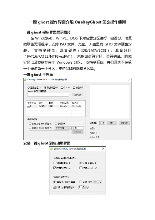
一键ghost主界面
安装一键ghsot到启动项界面
开机启动后主菜单
启动界面高级搜索
还原搜索到的ghost镜像
一自定义还原操作界面。
用OneKey Ghost安装win7系统(图文全教程)

win7安装包下载路径::8000/Win7%5F64%2EGHO?key=53cdc2 e22e7a306a75c19c0057e128c7&file_url=%2Fgdrive%2Fresource%2FFF%2F6C%2F FF679F76317E67AA4B1B14F06ABB15E31B86586C&file_type=0&authkey=361C86FD C9CBBB11BB67A7C270A094F77B84D24E6BB1EE6E81FB0574ABA42E6E&exp_time=135 7762749&from_uid=197125827&task_id=5768533814642926338&get_uid=100038 2243&f=&reduce_cdn=1&fid=eZZyBZNTwhoSQN81w+50/BT mB+HBoA/rAAAAAP9nn3YxfmeqSxsU8Gq7FeMbhlhs&mid=666&threshold=150&tid=5 F921F6038E352008C61CF83B3373D9D&srcid=7&verno=1接下来是教程:用U盘启动大师制作的U盘启动盘可以用安装U盘中的GHO系统工具来安装电脑系统,还能用Onekey Ghost来还原安装系统。
把下载好的系统镜像放到U盘启动盘里即可安装,此操作快捷,方便,去安装过程如下。
U盘启动盘制作教程:/jiaocheng/,详情请查看。
第一步:请认准U盘启动大师PE系统界面如下图:第二步:鼠标双击界面上的OneKey Ghost,选择系统镜像路径,单个会自动选择,GHO镜像文件和ISO镜像文件皆可第三步:点击确定后,会对镜像文件进行完整检查,选择是进行下一步第四步:此时正在对镜像进行完整检查,不需要任何操作即可,请稍后等蓝色链条走完第五步:蓝色链条走完后,会对系统镜像完整性做出判断,点击确定即可第六步:提示程序准备就绪,准备还原系统。
lenovo OneKey7.0_安装说明

联想一键拯救系统7.0一、安装OKR7的过程:打开计算机调出启动菜单,选择光盘或USB设备启动。
按照程序提示进行安装模式选择后进行安装全过程(包括:ASD模块安装、磁盘分区、复制OKR7的PE模块、设置语言、隐藏O盘),并在安装完成后关机!使用全新安装模式安装OKR7时,磁盘分区脚本对硬盘进行分区的模式为:C盘:根据手动输入的分区大小划分, NTFS,主分区,卷标为默认。
D盘:根据脚本定义自动划分,容量为磁盘总容量-15G-C盘容量,文件格式为NTFS, 扩展+逻辑分区,卷标为默认。
O盘:约15G,NTFS,主分区,卷标为LENOVO_PART安装OKR7的过程包括两种模式:全新安装、修复安装1)全新安装:WIN PE启动过程中,调用STARTNET.CMD查找OKR7系统安装文件路径并调用SETUP.CMD 启用OKR7的安装进程!此时系统会弹出如下图的选择框来进行安装模式选择。
“1”:全新安装。
此模式会清空硬盘上原有的所有分区,并根据脚本定义对硬盘重新分区、格式化等操作。
“2”、修复模式。
此模式要求硬盘末端有约15G未划分空间;安装程序会对这部分未划分空间重新划分、指驱动器号及卷标。
“3”、修复ASD模块。
在进行全新安装时,安装程序会弹出对话框(如下图),要求输入C盘大小,单位以MB 计算;并根据所输入的C盘容量及整个硬盘的容量来自动进行D盘和O盘的建立。
需要注意的是安装程序此时会清除原硬盘上的所有数据,其中包括全部的系统数据及用户数据,并会按照预定参数在硬盘上建立分区。
(C、D、O)2)修复安装:在程序弹出安装模式选择对话框时,如果选择“2”,安装程序会调用SETUP2.CMD进行修复安装,修复安装时硬盘分区应满足以下条件:硬盘末端预留约15G的未划分空间。
(此容量可根据实际需求做小幅修改)此时安装程序不会弹出输入C盘大小的对话框。
其它步骤同全新安装!语言设置:在OKR7的安装过程中,安装程序会弹出下图所示的对话框来选择安装后OKR7系统所使用的语言。
- 1、下载文档前请自行甄别文档内容的完整性,平台不提供额外的编辑、内容补充、找答案等附加服务。
- 2、"仅部分预览"的文档,不可在线预览部分如存在完整性等问题,可反馈申请退款(可完整预览的文档不适用该条件!)。
- 3、如文档侵犯您的权益,请联系客服反馈,我们会尽快为您处理(人工客服工作时间:9:00-18:30)。
使用说明
1.在电脑最后一个盘新建一个文件夹为system,把GHOSTXP.GHO (640MB) 和OneKey.exe
(3MB)两个文件放在里面
2.打开OneKey.exe ,出现以下界面
3.点击右上方的出现下图,照着下图的选择,按确认
4.安装完后回到了主界面
5.在这里点击打开,打开GHOSTXP.GHO,例如你在F盘新建一个文件夹为system,则就打开F:\ system\GHOSTXP.GHO
6.注意还原分区是选,然后就按下面界面的,
7.电脑会提示重启,点击
注意:①在重启过程中可能会自动进入OneKey还原,亦有可能在菜单手
动用↑↓键选择,当进入OneKey
还原时,就可以进行无人手操作
②此方法为电脑能正常开机下使用,
如果电脑不能正常开机,只能通
过光盘重装。