信号灯说明书范本
科海 新型号系列信号灯 说明书

科海新型号系列信号灯说明书一、概述科海信号灯供各种机械设备指示运行状态及故障情况使用,可用于纺织机械、数控机床、加工中心等领域;信号灯有灯泡型和LED型两大类产品,数百个品种,已具备规模生产能力,质优价廉,服务周到,外观造型和性能均达到国外先进水平,能与国外进口产品通用互换。
二、型号标志方法型号由六部分组成,前五部分分别标识发光体、灯罩尺寸、工作电压、灯节数、安装底座,分支编号表示同一型号中不同的灯罩颜色排列顺序、灯杆长度及弯直方式、电缆长度及连接方式等。
有关编排方法说明如下:1、发光体A——国产灯泡B——进口灯泡C——单层LED、直流稳压、公共端黑线为负D——单层LED、直流稳压、公共端黑线为正E——单层LED、交流电源F——双层LED、直流稳压、公共端黑线为负G——双层LED、直流稳压、公共端黑线为正H——采用灯泡灯头、内装LED、直流稳压、公共端黑线为负I——采用灯泡灯头、内装LED、直流稳压、公共端黑线为正J——双层LED、交流电源K——双层LED、直流非稳压、公共端黑线为负2、灯罩尺寸A——Φ40×52B——Φ52×64C——Φ55×60D——Φ68×62E——Φ40×28F——Φ52×463、工作电压6V、12V、24V、~220V4、灯节数1、2、3、4、55、安装底座A——4孔座图1B——4孔座图2C——4孔座图3D——3孔座图4E——3孔座图5F——3孔座图6G——3孔座图7H——3孔座图8I——3孔座图9J——3孔座图10K——单孔座图11L——橡胶座图12M——橡胶座图13N——可折弯金属座图14O——可折弯塑料座图15P——单孔座图166、分支编号表示同一型号中不同的灯罩颜色排列顺序,灯杆长度及弯直方式,电缆长度及连接方式,是否带音响。
示例1、BC24-4A 表示发光体为进口灯泡,灯罩尺寸为Φ55×60,工作电压为24V,灯节数为4节,灯罩颜色及顺序为红、黄、白、绿、直式灯杆,长度为20mm,电缆长度为500mm,采用国产插座连接,安装孔为4孔的A型底座。
信号灯 TYPE NE-24A NE-M1A TYPE NE-IL 使用说明书

Thank you very much for purchasing our PATLITE products.Request the installation and wiring be performed bya professional contractor if construction work isinvolved.Prior to installation, read this manual thoroughly before using this product to ensure correct use.If there are any questions concerning this product, refer to the contact information at the end of thisdocument and contact your nearest PATLITE Sales Representative.To the ContractorRead this manual carefully prior to installation.Be sure to return this manual to the customer.NE-24A NE-M1A NE-ILThe safety precautions that should always be followed in order to prevent injury to user or other individuals as well as prevent damage to property are described below.The level of injury or damage caused by ignoring these safety precautions and using the product improperly is categorizedand described below.NoticeTo ensure proper safety while using the signal tower, observe the following:Perform periodic pre-maintenance.As a precaution against problems occurring, use this product together with other equipment.Be sure to prevent electrostatic damage due to discharge when working with this product for wiring, exchangingunits, setting up parameters, etc. by discharging static electricity on your body, etc.(To prevent damage from static electricity, touch hands or other body parts to metals or an earth ground to discharge the body from static charge.)Use a soft cloth moistened with water to clean the globe or case.(Do not use thinner, benzine, gasoline or oil.)To ensure safety when this product is installed onto equipment, observe the following:Do not remove parts beyond those designed to be removed from this product.Do not modify or disassemble this product.Use only the specifi ed replacement parts listed in this document.Model Number Example NE-24A-R24 V DCRedModel Number Example NE-M1ATB-M12 ~ 24 V DCTouch SensorBuzzerMulticolorNE-ILModel Number Example NE-ILXB-MIO-LinkTouch Sensor (General-Purpose Digital/Analog Input)BuzzerMulticolor3 NE-24AUnit: mm611Ø 5646.5GlobeCase NameplateO-Ring Waterproof SheetMounting Holes *1Ø 4.5Wire Exit Hole Ø 13.3Bottom View(Without waterproof sheet)*1The mounting holes (2 positions) are designed to be punchedout.Drill the Ø 4.5 mounting holes from the top.NE-M1AUnit: mmNE-M1ANN-MColor: Red/Green/Blue/Yellow/Purple/Pink/Gray Cable length: 2090Cable diameter: Max. 6.5Material: PVCNE-M1ATB-M/NE-M1ANB-MElectrostatic Capacitive Color: Red/Green/Blue/Yellow/Purple/Pink/Gray Cable length: 2090Cable diameter: Max. 6.5Material: PVCØ21.1Mounting Holes *1 Ø 4.5Touch SensorRear View(Without Cable Gland)NE-ILUnit: mmL-L+L+L-IO-Link C/QM12 Connector Pin Con fi guration (NE-ILXB-M)M12 Connector Pin Con fi guration(NE-ILTB-M/NE-ILNB-M)IO-Link C/QAnalog GNDN.C.N.C.N.C.Analog IN Digital GNDDigital IN4NoticeThe following requirements are necessary for proper installation:- Install the signal beacon where excessive vibration is not present.- lnstall the signal beacon on a sturdy surface.- Install the signal beacon on a level surface.When waterproofi ng, apply a sealing coating onto the nuts on the backside of the installation surface.Provide a sealant coating around the wire exit hole, or use a Cable Gland.TYPENE-24AInstallation Example(1)Unlock the globe by holding and rotating it in a counter-clockwise direction, then lift it up.(2)Punch-out the mounting holes on the case by drillingØ 4.5 holes from the top.(3)Peel off the adhesive paper from the waterproof sheetand apply it to the case.(4)Affi x the product to the installation surface with screwsand nuts.(Installation screws and nuts are not included with thisproduct.)(5)After mounting the case, fi t the globe by aligning thepositioning marks and lock it by rotating in a clockwise.Installation Dimension [Unit: mm]M4 screw(Tightening torque: 0.6 N•m)When the Cable Gland is used, the hole must be large enough for it to fi t through.The recommended Cable Gland size is as follows:screw size: M16 × 1.5; screw length: shorter than 11 mm;outer diameter: less than 25 mm;material: plastic. (Tightening torque : 3 N•m)NE-M1AInstallation Example (1)Remove the globe by unscrewing it in a counter-clockwisedirection.(2)Punch-out the mounting holes on the case and buzzercase by drilling holes from the top.(3)Peel off the adhesive paper from the waterproof sheetand apply it to the case.(4)Affi x the product to the installation surface with screwsand nuts.(Installation screws and nuts are not included with thisproduct.)(5)Set the globe with aligning the positioning mark afterattaching the case, then turn the globe clockwise to lockit.Installation Dimension [Unit: mm]M4 screw (Tightening torque: 0.6 N•m)NE-ILInstallation Example(1)Remove the M30 nut.(2)Fix on the mounting surface with the M30 nut.(3)Connect the M12 cable to the M12 Connector.Installation Dimension [Unit: mm]Installation Holes(Ø 31) (Tightening torque: 4.5 N•m)5TYPENE-24A2Wiring Example(1)Remove the globe by unscrewing it in a counter-clockwise direction.(2)Connect the wires to the screwless terminal block.(3)Attach the globe by screwing it in a clockwise direction. The terminals have no polarity.NoticeMake sure that there is no slack in the internal wiring.Wiring hanging over the LED may cause a reduction in luminous intensity.Wiring examples vary depending on the driving method.(A)External Contact DriveFuse 1 APower Supply (Non-polar)External Contact(B)I/O Unit Drive(NPN Transistor)(C)I/O Unit Drive(PNP Transistor)[ Fuse ][ External Contact Capacity ][ Transistor (NPN or PNP) ]No signi fi cant inrush current present.NE-M1ANN-M/NE-M1ANB-MNE-M1ATB-M< NOTE >No need to connect the buzzer (purple wire) for NE-M1ANN-M. When the blink control is not necessary for NE-M1ANN-M/NE-M1ANB-M, no need to connect the blink control (pink wire). Be sure to insulate all unconnected lead wires one by one. Otherwise, electric shock or short circuit may occur.Inrush current: 15 A / 0.1 msSignal response time: 50 msNE-ILNE-ILXB-MGNDGND C/Q L+L-Analog InputExternal Sensor External Equipment (PWS, etc.)IO-Link MasterAnalog IN (Pin-2)Analog GND (Pin-1)Digital IN (Pin-4)Digital GND (Pin-3)L+ (Pin-5)IO-Link C/Q (Pin-8)L- (Pin-7)Digital InputNE-ILTB-M/NE-ILNB-MC/Q L+L-IO-Link MasterL+ (Pin-1)IO-Link C/Q (Pin-4)L- (Pin-3)[ External Contact Capacity ][ Analog Input ]Update interval: 20 ms[ Digital Input ]Update interval: 20 ms6NE-M1AThe LED light color and buzzer sound pattern can be set by removing the globe and adjusting the DIP switches. For touch cations, the touch sensor input switching can be set.sensor specifiTop view of product (with globe removed)OFFONUsing the NE-M1AThis product is able to use a signal wire to control the LED and buzzer.Each setting is adjusted using the setting DIP switches.NE-M1ATB can also be controlled with a touch sensor.About DIP SwitchesSettings can be changed as shown in the following tables. (All OFF as factory default settings)Buzzer Pattern SettingsChange the buzzer pattern as shown in the following table.Change Touch Sensor Input SettingsChange the operation of the touch sensor when it is touched as shown in the following table.Change Touch Sensor Input SettingsChange the operation of the touch sensor when it is touched as shown in the following table.E.g. 1)If momentary operation and a red color LED have been set, touching the touch sensor will light up in red,regardless of the color that the LED is being controlled with the signal wire (or if it is off).E.g. 2)If toggle operation and LED off have been set, touching the touch sensor once will turn the LED off, regardless ofthe color that the LED is being controlled with the signal wire. The LED will remain off until touching the light again, even if the condition of the signal wire has been changed.NoticeAlways move your hand away from the touch sensor after changing the DIP Switch.A bout the Touch SensorTo turn the touch sensor to ON, touch the following symbol on the top of the globe with the middle of your fi nger or palm of your hand. The response time of the touch sensor is 100 ms.Touch hereNoticeThe touch sensor may not respond if you touch the sensor too slowly.Touching continuously for 60 seconds is considered an incorrect operation, and the condition when touched is forciblycanceled. The light will respond by releasing your hand from the globe and touching it again.NE-ILUsing the NE-ILThis product is an IO-Link compliant product.Follow the instructions for wiring up “ 5 Wiring ”(P. 15).The IO-Link master can control the LED and the buzzer.The functions that can be used differs depending on the product.Available functions are shown in the following table.Changing the “Operating Mode” settings enables operation in the following modes: Color Specifi cation ModeLevel ModeAnalog Input Mode (NE-ILXB only)Digital Input Mode (NE-ILXB only)The parameters used in each mode are shown in the following table.Refer to “Common Items for Each Mode” (P. 23) for common items.Parameter SettingsFor information about the parameter settings, please download the IODD from the LR6-IL page on our homepage (https:// /).Please also download and use the parameter sheet in the same way.Common Items3.2mA ~ 4 mA (-25 ~ 0) / 4 mA ~ 20 mA (0 ~ 500) / 20 mA ~ 21 mA (500 ~ 531)Color Specifi cation ModeIn this mode, LED and buzzer details are specifi ed for control.Other settings are specifi ed using the parameters.Send the processed data by referring to the table below.Level ModeIn this mode, LED and buzzer details are set using the parameters, and controlled with the values of the processed data.Values from 0 (0x000) to 500 (0x1F4) can be entered as analog values.Refer to “Analog Control Examples)” (P. 22) for an example of control using Analog Input Mode.Analog Input ModeIn this mode, LED and buzzer control uses analog input values without using processed data. Settings are specifi ed using the parameters.Refer to the following image for values used for analog input.Current value21mA20mA4mA3.2mA0 -25500531 Analog Input ValueResolutionA nalog Control Examples)For Index2010 enter a value that is larger than the value specifi ed by the lower byte. If 0 is specifi ed, the parameter for that byte will be ignored.byte11 does not exist for Index2010, but specifying it for Index2011 to 2013 specifi es the operation up to set the threshold value for byte1 from default conditions.Due to variations in the analog input value, the value specifi ed for Index2010 is the threshold value, and hysteresis is specifi ed to 20 for the downward direction. Note that if the specifi ed threshold value is 20 or less, the hysteresis is 1.Digital Input ModeIn this mode, LED and buzzer control uses digital input values without using processed data.Settings are specifi ed using the parameters.C ommon Items for Each ModeAbout LED ColorsThe “LED Color” used in each mode is shown in the following table.About LED PatternsThe “LED Pattern” used in each mode is shown in the following table.About Buzzer PatternsThe “Buzzer Pattern” used in each mode is shown in the following table.About the Touch SensorRefer to “About the Touch Sensor” (P. 18) for the NE-M1A.7NE-24ATroubleshoot problems that occur by following the instructions in the table below.NE-M1ATroubleshoot problems that occur by following the instructions in the table below.NE-ILTroubleshoot problems that occur by following the instructions in the table below.8The requirements in each law and regulation are only included in the language designated by each law and regulation.Check the instruction manuals published in each language.*1If installed on a fl at surface using a cable glandProduct Name Signal BeaconModel NE-M1ANN-M NE-M1ANB-M NE-M1ATB-M Rated Voltage 12 V DC to 24 V DC Voltage tolerance range 10 V DC to 30 V DCRated currentconsumption Standard12 V DC 55 mA 80 mA24 V DC 45 mA 65 mA Maximum12 V DC 65 mA 95 mA24 V DC 50 mA 75 mA Rated powerconsumption Standard12 V DC 0.7 W 1.0 W24 V DC 1.1 W 1.6 W Maximum12 V DC 0.8 W 1.2 W24 V DC 1.2 W 1.8 WStandby current 20 mA or less Inrush current 0.4 A / 2 msecAmbient operating temperature -25 °C to +60 °C Ambient operating humidity 90 % RH or less; No condensation Ambient storage temperature -40 °C to +75 °C Ambient storage humidity 90 % RH or less; No condensation Installation location Indoor Installation direction All directions Protection Rating IP67, NEMA TYPE 4X, 13IP65, NEMA TYPE 4X, 13EnvironmentalconditionsWhen installed in the upright directionVibration Resistance 5 M Ω or more at 500 V DC between charging parts and non-charging metal parts Withstanding voltage 1 minute at 500 V AC between charging parts and non-charging metal parts Sound pressure level -Typ. 88 dBEnvironmentalconditionsAt 1 m in front from the center, buzzer pattern 2 “Continuous beep sound”Touch Sensing Input Method -Electrostatic CapacitanceFlashing cycle 500ms ON / OFF -Mass (Tolerance: ±10 %)0.15 kg 0.17 kg Exterior dimensions Refer to the Outer Dimension DrawingCompliance standards EMC Directive (EN 61000-6-4, EN 61000-6-2)RoHS Directive (EN 50581)UL 508, CSA-C22.2 No. 14FCC Part 15 Subpart B Class A KC (KN 61000-6-4, KN 61000-6-2)NotesThe brightness of each LED may differ according to the characteristics of the LED orcolor variations in each individual LED or the product.Model descriptionNE - M1 A T B - MBuzzerB :With Buzzer N :No Buzzer Touch SensorT :With Touch Sensor N :No Touch Sensor Luminous colors M :MulticolorVoltageM1:12 ~ 24 V DCProduct NameIO-Link Signal BeaconModel NE-ILNB-MNE-ILTB-M NE-ILXB-MRated Voltage24 V DCVoltage tolerance range18 V DC to 30 V DCRated currentconsumption Standard 80 mA Maximum100 mA Rated power consumptionStandard2.0 W Maximum2.4 WInrush current10 A / 0.2 msec Ambient operating temperature -25 °C to +60 °CAmbient operating humidity 90 % RH or less; No condensationAmbient storage temperature -40 °C to +75 °CAmbient storage humidity 90 % RH or less; No condensationInstallation location IndoorInstallation direction Upright directionProtection RatingIP65, NEMA TYPE 4X, 13Environmental conditionsWhen installed in the upright directionVibration Resistance 5 M Ω or more at 500 V DC between charging parts and non-charging metal parts Withstanding voltage 1 minute at 500 V AC between charging parts and non-charging metal partsSound pressure levelTyp. 88 dBEnvironmental conditionsAt 1 m in front from the center, buzzer pattern 1 “Continuous beep sound”Touch Sensing Input Method-Electrostatic CapacitanceAnalog input range- 4 mA to 20 mA Digital Input -Voltage contact(NPN/PNP Transistor)Mass (Tolerance: ±10 %)0.10 kgExterior dimensionsRefer to the Outer Dimension Drawing Compliance standardsEMC Directive (EN 61000-6-4, EN 61000-6-2)RoHS Directive (EN 50581)UL 508, CSA-C22.2 No. 14FCC Part 15 Subpart B Class A KC (KN 61000-6-4, KN 61000-6-2)Notes The brightness of each LED may differ according to the characteristics of the LED orcolor variations in each individual LED or the product.Model descriptionNE - IL T B - MTouch SensorX :With Touch Sensor(General-Purpose Digital/Analog Input)T :With Touch Sensor N :No Touch SensorBuzzerB :With Buzzer N :No Buzzer Luminous colors M :MulticolorThese are the various parts for the customer to use when repairing or replacing parts for the product.The optional parts for this product are listed below. (Top line: Part Name; Bottom: Model)Model Number Con fi gurationExternal Diagram (Unit: mm)Applicable pole Applicable bracket47General Speci fi cations Product NamePole Bracket ModelNE-001D Installation location IndoorInstallation direction Upright directionMass (Tolerance: ±10 %)0.031 kg(With one sealing rubber attached)Sealing rubberBlack (for Ø 22 mm pole)Gray (for Ø 25 mm pole)NE-ILNE-24ANE-M1ARemove the M30 nut on the main unit.Recommended installation screw: 4 × 12 mmSelf tapping screw for plastics Recommended torque: 1 N mModel Number Confi gurationExternal Diagram(Unit: mm)General Specifi cationsProduct Name Wall Mounting BracketModel NE-002DInstallation location IndoorInstallation direction Upright directionMass (Tolerance: ±10 %)0.034 kgNE-IL NE-24ANE-M1ARecommended installation screw: M4 × 20 mm Pan head screw M4 Hexagon nutRecommended torque: 0.6 N mParts for International ModelsModel v Confi gurationExternal Diagram(Unit: mm)General Specifi cationsProduct Name NPT Pole BracketModel SZP-092DInstallation location IndoorInstallation direction Upright directionMass (Tolerance: ±10 %)0.023 kgMounting the NPT polePress down on A when mounting to the pole. Forcibly mounting it may cause damage.(Tightening torque: 2.25 N·m)1/2" NPT poleNE-IL NE-24ANE-M1ARemove the M30 nut on the main unit.Recommended installation screw: 4 × 12 mmSelf tapping Screw for plastics Recommended torque: 1 N mThe following optional parts can also be used with the NE-24A and NE-M1A.。
交通行业智能交通信号灯使用方法说明书
交通行业智能交通信号灯使用方法说明书一、概述交通行业智能交通信号灯是一种采用先进的智能控制技术,用于交通信号控制的设备。
本说明书将详细介绍智能交通信号灯的使用方法及相关注意事项。
二、产品特点1. 智能控制技术:采用先进的智能控制算法,能够根据交通流量、车速等参数精确控制信号灯的变化,优化道路通行效率。
2. 多功能显示屏:信号灯配备多功能显示屏,可以显示各类交通信息,如倒计时、速度限制等,提高道路安全性和信息传达效果。
3. 远程监控系统:信号灯连接远程监控系统,能够实现对信号灯的实时监控和远程控制,提高管理效率。
4. 省电环保:采用节能高效的LED光源,降低能耗并减少环境污染。
三、使用方法1. 安装:选择适合的位置进行信号灯安装,确保信号灯可以清晰可见,并与交通流量方向一致。
2. 连接电源:将信号灯正确接入交流电源,注意接线正确且稳固。
3. 调试:接通电源后,随系统启动进行信号灯调试。
确保各个信号灯灯珠正常工作,显示屏正常显示,无异常情况存在。
4. 参数设置:根据实际道路情况和交通需求,设置信号灯的相关参数,如绿灯时长、黄灯时长等。
不同的交通场景需要合理调整参数,以达到最佳交通流效果。
5. 联网操作:将信号灯连接至远程监控系统,确保信号灯正常与系统通信。
系统操作人员应熟悉相关软件和监控界面,了解信号灯的状态和实时数据。
6. 日常维护:定期检查信号灯的运行状态,当发现故障或异常情况时,及时进行维修或更换。
保持信号灯的清洁,避免灯珠污损影响显示效果。
四、注意事项1. 本产品必须由专业技术人员安装和调试,确保安全可靠。
2. 使用过程中应根据实际道路和交通情况进行参数调整,提高交通效率。
3. 严禁私自修改信号灯的控制参数和程序,以防止信号混乱和交通事故。
4. 信号灯显示屏上的信息应准确、清晰,对于故障信息,应及时修复或更换显示屏。
5. 对于远程监控系统的操作人员,应具备相关资质和技能,且遵守相关规章制度。
车道通行灯产品说明书(XY-ZX-101)

XY-ZX-101车道通行灯产品说明书广东新粤交通投资有限公司车道通行信号灯产品说明书车道通行信号灯用于各类路桥收费站,安装在收费车道旁、收费亭侧后方,用于指示车道通行状态,红灯禁止通行,绿灯可以通行。
应用于电脑收费系统时,由车道控制器控制红、绿灯状态。
技术参数及规格机箱采用不锈钢材料,厚度1.5mm。
具有防锈、防暴功能。
采用超高亮度发光二极管,带有遮光罩,显示清晰,省电、耐用。
全密封结构,具有防水、防尘功能。
防水、防尘达到IP55工业标准。
环境温度:-20℃~+60℃相对湿度:10%~95%非冷凝电源:交流220V±15% ( 50Hz )功率:小于20WMTBF:10,000小时。
MTTR:0.5小时。
防护等级:IP55。
外形尺寸1、XY-ZX-101(图1)红绿双色灯,发光面直径为200mm,箱体尺寸为260x260x95,整体高度为1.2米。
2、XY-ZX-102(图2)两个单色灯,一红一绿,发光面直径为200mm,箱体尺寸为260x520x95mm。
3、XY-ZX-103(图3)红绿灯分别用叉和箭头表示,箱体尺寸为3200x260x95,发光面尺寸:直径200mm.图1 XY-ZX-101 图2 XY-ZX-102 图3 XY-ZX-103车道通行信号灯控制接口1、电源机箱内电路板下面电源变压器右侧有一接线座,上有‘L’,‘N’,‘FG’(或接地符号)标志的接线端子,分别接交流220V电源的相线,零线,地线。
2、控制方式机箱内电路板右下方有一接线端子J2,其接线端从左至右标有‘GND’、‘-’、‘+’、‘VCC’,其中‘-’、‘+’为控制电压输入端的负极和正极,‘GND’、‘VCC’为内部电源引出端。
当在‘+’、‘-’端之间加上一10~15V的直流电压时,车道通行灯显示绿色信号,不加电压时,车道通行灯显示红色信号。
若使用内部电源,可将‘+’、‘VCC’短接,用继电器触点或开关控制‘GND’、‘-’之间的通断来控制红绿显示。
QLight QTG50 60 70系列LED信号灯产品说明书
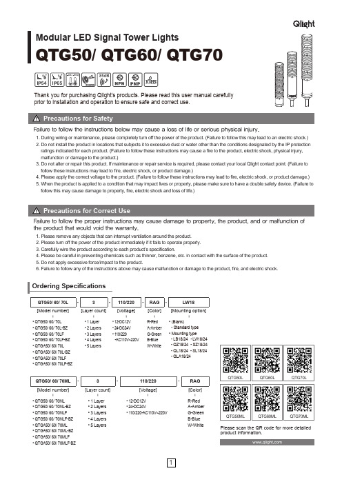
Modular LED Signal Tower LightsQTG50/ QTG60/ QTG70546585dB5030QTG50L QTG50ML QTG60L QTG60ML QTG70LQTG70MLPlease scan the QR code for more detailed product information.QTG50/ 60/ 70L -3-110/220-RAG -LW18[Model number][Layer count][Voltage][Color][Mounting option]|||||• QTG50/ 60/ 70L • QTG50/ 60/ 70L-BZ • QTG50/ 60/ 70LF • QTG50/ 60/ 70LF-BZ • QTGA50/ 60/ 70L • QTGA50/ 60/ 70L-BZ • QTGA50/ 60/ 70LF • QTGA50/ 60/ 70LF-BZ• 1 Layer • 2 Layers • 3 Layers • 4 Layers • 5 Layers• 12-DC12V • 24-DC24V • 110/220-AC110V~220VR-Red A-Amber G-Green B-Blue W-White• (Blank)- Standard type • Mounting type- LB18/24 - L W 18/24 - QZ18/24 - SZ18/24 - QL18/24 - SL18/24 - QLA18/24QTG50/ 60/ 70ML -3-110/220-RAG [Model number][Layer count][Voltage][Color]||||• QTG50/ 60/ 70ML • QTG50/ 60/ 70ML-BZ • QTG50/ 60/ 70MLF • QTG50/ 60/ 70MLF-BZ • QTGA50/ 60/ 70ML • QTGA50/ 60/ 70ML-BZ • QTGA50/ 60/ 70MLF • QTGA50/ 60/ 70MLF-BZ• 1 Layer • 2 Layers • 3 Layers • 4 Layers • 5 Layers• 12-DC12V • 24-DC24V• 110/220-AC110V~220VR-Red A-Amber G-Green B-Blue W-WhiteThank you for purchasing Qlight’s products. Please read this user manual carefully prior to installation and operation to ensure safe and correct use.Failure to follow the instructions below may cause a loss of life or serious physical injury.1. Please remove any objects that can interrupt ventilation around the product.2. Please turn off the power of the product immediately if it fails to operate properly.3. Carefully wire the product according to each product’s specification.4. Please be careful in preventing chemicals such as thinner, benzene, etc. in contact with the surface of the product.5. Do not apply excessive force/impact to the product.6. Failure to follow any of the instructions above may cause malfunction or damage to the product, fire, and electric shock.Failure to follow the proper instructions may cause damage to property, the product, and or malfunction of the product that would void the warranty.1. During wiring or maintenance, please completely turn off the power of the product. (Failure to follow this may lead to an electric shock.)2. Do not install the product in locations that subjects it to excessive dust or water other than the conditions designated by the IP protection ratings indicated for each product. (Failure to follow these instructions may cause a fire to the product, electric shock, physical injury, malfunction or damage to the product.)3. Do not alter or repair this product. If maintenance or repair service is required, please contact your local Qlight contact point. (Failure to follow these instructions may lead to fire, electric shock, or product damage.)4. Please apply the correct voltage to the product. (Failure to follow these instructions may lead to fire, electric shock, or product damage.)5. When the product is applied to a condition that may impact lives or property, please make sure to have a double safety device. (Failure to follow this may cause damage to property, fire, electric shock and loss of life.)••QTG60ML : DC QTG60MLF : DC QTG60ML-BZ : DC QTG60ML : AC QTG60MLF-BZ : DC QTG60MLF : AC QTG60ML-BZ : AC QTG60MLF-BZ : ACQTG60L : DCQTG60LF : DC QTG60L-BZ : DCQTG60L : ACQTG60LF-BZ : DCQTG60LF : AC QTG60L-BZ : AC QTG60LF-BZ : ACQTG70ML : DC QTG70MLF : DC QTG70ML-BZ : DC QTG70ML : AC QTG70MLF : AC QTG70ML-BZ : ACQTG70MLF-BZ : DCQTG70MLF-BZ : AC QTG70L : DC QTG70LF : DC QTG70L-BZ : DCQTG70L : AC QTG70LF : AC QTG70L-BZ : AC QTG70LF-BZ : DCQTG70LF-BZ : ACQTG50ML : DC QTG50MLF : DC QTG50ML-BZ : DC QTG50ML : AC QTG50MLF-BZ : DC QTG50MLF : AC QTG50ML-BZ : AC QTG50MLF-BZ : ACQTG50L : DCQTG50LF : DC QTG50L-BZ : DCQTG50L : ACQTG50LF-BZ : DCQTG50LF : AC QTG50L-BZ : AC QTG50LF-BZ : AC• QTG50(M)L• QTG60(M)L• QTG70(M)L■Wiring using external contact• In case of wiring with external contacts, refer to the wiring diagrams below according to your product’s type and voltage setting.• DC steady type cable specification: External power/ signal line - UL1007 AWG22(0.3sq) 400mm• AC steady, AC/DC steady/flashing type cable specification : External power line - UL1015 AWG18(0.75sq) × 2C 400mm,External signal line - UL1007 AWG22(0.3sq) 400mm■Wiring using transistor• When using a transistor, please choose between the NPN or PNP type transistor which best matches the voltage and product type, then connect them correctly according to the wiring diagrams below.• DC steady type cable specification: External power/ signal line - UL1007 AWG22(0.3sq) 400mm• AC steady, AC/DC steady/flashing type cable specification : External power line - UL1015 AWG18(0.75sq) × 2C 400mm,External signal line - UL1007 AWG22(0.3sq) 400mmParts DefinitionPipe(AL)Installation Environment and Protection Rating• This product is designed for indoor use with protection rating of IP65(standard type) and IP54(buzzer type).• If the product is installed in locations that subject it to excessive dust or water other than the designated IP protection rating indicated(IP65), it may cause malfunction or damage to the product.• For further information, please visit our website ().How to Change Lens Kit• Disassembling lens kits① Twist the upper lens kit in a counter-wise direction so the “I” mark from both kits align.② Disassemble by removing the upper lens kit from the lower one.• Assembling lens kits① Put the two lens kits together by aligning the upper lens’ “I” mark and the lower lens’ “I” mark together.② Lock the two kits by twisting the upper lens kit in a counter -wise direction so the upper lens’ “◁” mark aligns with the lower lens’ “I” mark.Lens modules are connected through cone-shaped contact point. In case the contact point is damaged, it may cause a contact failure.※CautionsContact Point① Machine holes on the mounting surface referring to thediagram below.② First, remove the flange nuts from bolts and place the productthrough the mounting surface holes.③ F asten the flange nuts on the opposite side of the mountingsurface until the product is tightened securely.■ QTG50M/ QTG60M/ QTG70M - Direct Mounting Type ModelBuzzer volume is reduced by sliding the volume control lever to the left as show in the diagram to the left.( Min. 65±4dB/m )Raise/ Increase the buzzer volumeby sliding the control lever to the right as shown in the diagram to the left.( Max. 85±4dB/m )• Please refer to the dimensions below for installation of mounting brackets.■ QTG50ML/ QTG60ML/ QTG70ML - Direct Mounting Type ModelQTG70M• Buzzer type model with 2 different sounds of long beeping sound and short beeping sound is available upon request.■ 2 Sound Buzzer Type■ QTG50L/ QTG60L -Pole Mounting Type Model■ QTG70L - Pole Mounting Type Model• Qlight products are designed to meet strict quality and technical standards. Thus, the Qlight brand is widely recognized for its high quality and technical innovations from leading institutions around the world.QlightCo.,|*******************Head Offi ce | A-412, 579, Gyeongin-ro, Guro-gu, Seoul, Korea T el. +82-80-328-2222 Fax : +82-2-2679-6154Factory | 185-25, Mukbang-Ro, Sangdong-Myeon, Gimhae-si, Gyeongsangnamdo, Korea T el. +82-80-328-1111Qlight Overseas Sales Dept | 185-25, Mukbang-Ro, Sangdong-Myeon, Gimhae-Si, Gyeongsangnam-Do, Korea T el : +82-55-328-4082Qlight Public Relations & Marketing T eam Offi ce | Nakdong-daero, Sasang-gu, Busan, Korea(Eomgung-Dong) T el : +82-51-245-0017QlightUSA,|*******************3003 North First Street, Suite #341, San Jose, CA 95134 USA T el. +1.408.519.5740 Fax. +1.408.519.5739SHANGHAIQlightElectronicCo.,|*******************China Factory/ Shanghai Sales Offi ce | #19, Nanda Road, Baoshan Area, Shanghai, China T el. +86.21.6651.7100 Fax. +86.21.6315.3929 For your safety Specifi cation and dimensions listen in this catalogue subject to change wuthout notice for product quality improvemont.The newest prouct information is available on our web site.()Please read the instruction Manual attached to the product carefully before installation and use.EN-1904A。
ND16系列 信号灯 说明书
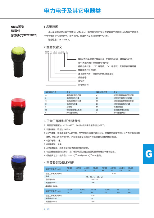
ND16-22CS/4 AC380V ND16-22CS/2 AC/DC36V
ND16-22CS/2 AC/DC6V ND16-22CS/2 AC/DC48V
52 15
Φ30.5
ND16-22DS/4 AC110V
ND16-22DS/2 AC/DC12V
ND16-22DS/4 AC220V ND16-22DS/2 AC/DC24V
含义 平面梅花圆形灯罩 平面圆台形灯罩 弧面波纹圆形灯罩 弧面圆形灯罩 双色灯 蜂鸣器(断续闪烁式) 蜂鸣器(断续式)
辅助规格代号 AS BS CS DS BK LC L
含义 超短型平面梅花圆形灯罩 超短型平面圆台形灯罩 超短型弧面波纹圆形灯罩 超短型弧面圆形灯罩 快速接线型 蜂鸣器(连续长亮式) 蜂鸣器(连续式)
母结构,使产品在安装板孔径Φ22.5、Φ25.5的情况下通用。 5.2 使用说明 5.2.1 安装步骤: a.信号灯在安装使用前应先检查一下额定工作电压是否符合使用要求; b.使用前,先拆下信号灯上的塑料锁定螺母,把信号灯从面板前方装入,再从面板后拧紧塑料锁定螺母
使信号灯紧固在面板上,最后把电源 线接上。
N D 16-□□ □□ /□ □
字母C表示头部防护等级IP65,无字母为IP40,蜂鸣器为IP20, 带"F"表示可用于电容器柜的放电灯 结构分类代号:“2”电阻式,“4”电容式,无数字表示蜂鸣器 辅助规格代号(见表1) 基本规格代号:22表示信号灯颈部直径 设计序号 信号灯 企业特征号
辅助规格代号 A B C D S 0V ND16-22S/4 AC 220VF ND16-22S/4 AC 380VF
64max 13
Φ30.5max
ND16-22F AC380V ND16-22F AC220V ND16-22F AC/DC110V ND16-22F AC/DC48V ND16-22F AC/DC36V ND16-22F AC/DC24V ND16-22FS AC380V ND16-22FS AC220V
道路交通信号灯使用说明书

绿色 ≥400 500±5 ≥30° ≥300 有 有
JD300 红色 ≥400 625±5 ≥30° ≥300 有 有
135 ≤15
170 ≤15
黄色 ≥400 590±5 ≥30° ≥300 有 无
170 ≤15
绿色 ≥400 500±5 ≥30° ≥300 有 有
FX300 红色 ≥400 625±5 ≥30° ≥300 有 有
3.物理٠机械性能 3.1 抗风压符合 GB14887 的相关要求 3.2 抗振动要求符合 GB14887 要求 3.3 防护等级大于 IP53
4.适应环境 4.1 信号灯工作环境温度为-40ºС¯50ºС,可耐-40ºС 和+80ºС 的高低温测试 4.2 温度为 25ºС 时,空气相对湿度不大于 95%
3
第三节 安 装 说 明
1。道路交通信号灯的安装方式:
垂直安装(横装)方式
垂直安装(竖装)方式
竖杆安装方式
注:如果您对安装方式有特殊的要求,我们根椐您的要求进行设计制作。
2.道路交通信号灯装饰板安装说明
装饰板总共有四件(400 型单灯除外)如左图所示①②③④,
装饰板安装在灯具的背面,首先将两件装饰板(①②)按图中箭
三灯 600 1350 70 1040 1190 1350 70
四灯 600 1700 70 1390 1540 1700 70
五灯 600 2050 70 1740 1890 2050 70
f
h
w
195 200 140
195 200 140
195 200 140
195 200 140
195 200 140
1
第三节
1.道路交通信号灯总装图示:
道路交通信号灯使用说明书

道路交通信号灯使用说明书
一、引言
道路交通信号灯是一种重要的交通控制设施,它在道路交通中起着非常关键的作用。
本说明书旨在向用户提供关于道路交通信号灯的基本知识和正确使用方法的介绍,以确保交通信号灯的有效使用,提高道路交通的安全性和效率。
二、信号灯分类
道路交通信号灯可以分为三个主要分类:
1. 红灯:红色信号表示禁止通行,所有车辆都必须停下来等待信号灯变绿。
2. 绿灯:绿色信号表示允许通行,所有车辆可以按照交通规则继续前行。
3. 黄灯:黄色信号表示警示,车辆应当减速并做好停车准备。
三、信号灯的正确使用方法
1. 遇到红灯时,驾驶员应立即停车,等待信号灯变绿后再行驶。
在停车等待的过程中,车辆应该停在指定的停止线后,避免占用人
行横道或阻塞交叉口。
2. 遇到绿灯时,驾驶员可以继续行驶,但应注意其他交通信号
和交通标志,确保安全通行。
3. 遇到黄灯时,驾驶员应减速并做好停车准备。
如果车辆已经
越过停止线,应尽量通过路口,避免急刹车引发危险。
4. 在遇到交通信号灯故障时,驾驶员应按照交通规则行驶,尽
量避免交通事故发生。
四、注意事项
1. 不要闯红灯。
闯红灯是非法和危险的行为,不仅会给自己带
来风险,还会危及他人的生命安全。
2. 不要过于依赖信号灯。
虽然信号灯是交通控制的重要手段,
但驾驶员仍应当保持警惕,注意其他车辆和行人的情况,确保自身
和他人的安全。
- 1、下载文档前请自行甄别文档内容的完整性,平台不提供额外的编辑、内容补充、找答案等附加服务。
- 2、"仅部分预览"的文档,不可在线预览部分如存在完整性等问题,可反馈申请退款(可完整预览的文档不适用该条件!)。
- 3、如文档侵犯您的权益,请联系客服反馈,我们会尽快为您处理(人工客服工作时间:9:00-18:30)。
唐山学院《数字电子技术》课程设计题目交通信号灯控制电路设计系 (部) 信息工程系班级姓名学号指导教师成凤敏王蕾叶双岳姝2013年7月8日至 7月12 日共1周2013年 7月 11 日《数字电子技术》课程设计任务书课程设计成绩评定表目录1 引言 (1)1.1设计目的 (1)1.2设计背景 (1)2 设计原理 (3)3 总体设计 (4)3.1单元电路设计 (4)3.1.1 秒脉冲产生电路 (4)3.1.2 十二进制计数器 (5)3.1.3 分频器电路的设计 (6)3.1.4 直流稳压电源 (8)3.1.5 信号灯驱动电路的设计 (9)3.1.6白天夜间模式切换的设计 (9)3.1.7交通灯逻辑控制电路 (10)3.2时序仿真结果 (12)4 设计总结 (16)参考文献 (17)附录1 器件明细表 (18)附录2 仿真电路图 (19)1 引言1.1设计目的学习了一个学期的《数字电子技术》课程,这次的课程设计主要综合了解与运用所学的知识,通过这次课程设计来检查这一学期的学习状况。
通过制作来了解交通灯控制系统,了解译码器、计数器、寄存器芯片的作用。
交通灯控制系统主要是实现城市交叉路口红绿灯的控制。
在现代化的大城市中,十字交叉路口越来越多,在每一个交叉路口都需要有一个准确的时间间隔和转换顺序,这就需要一个安全、自动的系统对红、黄、绿的转化进行管理。
本次的设计就是基于此目的进行的。
设计交通信号控制灯要求某方向绿灯点亮20秒,然后黄灯点亮4秒,最后红灯点亮24秒。
在该方向为绿灯和黄灯点亮期间,另一方向红灯点亮。
如果以4秒作为时间计量单位,则某一方向绿、黄、红三种指示灯点亮的时间比例为5:1:6。
从点亮要求可以看出,有些输出是并行的:如南北方向绿灯亮时,东西方向红灯亮;南北方向黄灯亮时,东西方向红灯亮;南北方向红灯亮时,东西方向绿灯亮;南北方向红灯亮时,东西方向黄灯亮。
信号灯采用LED红、绿、黄发光二极管模拟。
夜间工作方式南北东西各方向黄灯亮,且每秒闪动一次。
其它灯不亮。
要求设置一个手动开关,用它控制白天和夜间工作方式。
1.2设计背景随着世界范围内城市化和机动化进程的加快,城市交通越来越成为一个全球化的问题。
城市交通基础设施供给滞后于高速机动化增长需求,道路堵塞日趋加重,交通事故频繁,环境污染加剧等问题普遍存在。
目前,全国大中城市普遍存在着道路拥挤、车辆堵塞、交通秩序混乱的现象,交通事故频发,这给人民的生命财产安全带来了极大的损失。
如何解决城市交通问题已成为全社会关注的焦点和大众的迫切呼声。
探究城市交通发展中存在问题的原因,无论是从宏观上还是从微观上分析,其根本原因在于城市交通系统的管理机制不适应。
城市交通控制系统(UTC ,Urban Traffic Control System)是现代城市智能交通系统(IDJ ,Intelligent transport system)的组成之一,主要用于城市道路交通的控制与管理。
城市平交路口实现交通信号控制是城市交通管理现代化的基本标志之一,是提高交通管理效能的重要技术手段。
路口信号控制器是控制交叉路口交通信号的设备,它是交通信号控制的重要组成部分。
各种交通控制方案,最终都要由路口信号控制器来实现。
为了确保十字路口的行人和车辆顺利、畅通地通过,往往采用电子控制的交通信号来进行指挥。
伴随着社会的发展以及人类生活水平的提高,汽车的数量在不断增加。
Multisim10是一款知名的EDA仿真软件,由加拿大IIT、公司于2007年推出最新版本。
在Windows环境下,Multisim10软件有一个完整的集成化设计环境,它将原理图的创建、电路的测试分析、结的图表显示等全部集成到同一个电路窗口中。
在搭建实际电路之前,采用Multisim10仿真软件进行虚拟测试,可使实验方法和实验手段现代化,扩展实验容量,使实验内容更完备,提高了实验效率,节省大量的实验资源。
Multisim10软件进行设计仿真分析的基本步骤为:设计创建仿真电路原理图→电路图选项的设置→使用仿真仪器→设定仿真分析方法→启动Multisim10仿真。
因此本次课设能深入了解交通信号灯的应用原理,更好的掌握所学知识,将理论联系实际,而且在实际操作中培养自己的实际动手能力,将理论应用与实际生活中。
2 设计原理设计交通信号控制灯要求白天的工作方式如图2-1:图2-1 信号指示灯白天点亮流程图夜晚的工作方式是:南北东西各方向黄灯亮,且每秒闪动一次,其他灯不亮,因此总的设计框图如图2-2:图2-2 整体电路设计框图根据交通灯的性能要求以及整体电路图,设计本次课程设计的交通灯电路。
3 总体设计3.1 单元电路设计3.1.1 秒脉冲产生电路由于黄灯点亮时按秒闪动以及时间显示按秒倒计时,所以需要设计秒脉冲产生电路。
秒脉冲产生电路实际就是一个多谐振荡电路,它可以是用门电路和电阻、电容组成的多谐振荡电路,也可以是用定时器555和电阻、电容组成的多谐振荡器。
为了电路简单和调节振荡周期方便,选择用555定时器组成多谐振荡器。
其中由555构成本次课设的1秒脉冲电路如图3-1所示:Vcc图3-1 555定时器组成多谐振荡器原理图振荡周期与频率的计算公式为:T=(R1+2R2)Cln2=0.7(R1+2R2)C,电源电压为Vcc=5V,其中电路图中C1的作用是防止电磁干扰对振荡电路的影响,一般选用0.01F的瓷片电容。
再次课程设计中要求输出T=1S,选取电容为C=10μF,R1=560kΩ,根据振荡周期计算,选择电阻R2=434kΩ。
由于存在系统误差,经调试取R2=432kΩ。
在Multisim中进行仿如图3-2:图3-2 555多谐振荡器仿真图从图3-2中可以看出T=1.034S,这与要求相符。
3.1.2 十二进制计数器由信号灯白天点亮流程图可以得知,任何方向的信号灯的一个工作循环为十二进制(绿、黄、红时间比例为5:1:6),因此需要设计十二进制计数器,循环工作控制白天信号灯的点亮。
因此,用移位寄存器组成十二进制计数器,拟选用8位串入并出移位寄存器74LS164。
用74LS164组成的12进制扭环型计数器电路 ,其电路图如图3-3所示。
3.1.3 分频器电路的设计上述十二进制计数器的时间单位为4秒,即它的CP 脉冲为4秒。
为了使整体电路工作步调一致,4秒脉冲应该利用秒脉冲经分频获得,这就需要设计一个4分频器电路。
秒脉冲经4分频后得到4秒脉冲,将其作为十二进制计数器的CP 脉冲。
本次课程设计使用两个D 触发器组成4分频器电路。
74LS74是内有两个D 触发器的TTL 集成电路,将每一触发器接成触发器,两级串联就实现4分频,即输入1S 脉冲,输出4S 脉冲。
CP D Qn+1 0XQn1 0 0 111表3-1 74LS74真值表V CC Q H Q G Q F Q E R D CPA B Q A Q B Q C Q D GND141 74LS1648 7图3-3 74LS164引脚图图3-4 四分频的电路原理图在Multisim中进行仿如图3-5:从图中可以看出由555定时器组成的多谐振荡器将1S脉冲输送给2分频D触发器,两级串联就实现4分频,即输入1S脉冲,输出4S脉冲。
由示波器得T=4.095S,这与要求相符。
3.1.4 直流稳压电源直流稳压电源包括变压器降压、二极管(或整流桥)整流、电容滤波、集成稳压芯片稳压四部分。
作为一个实际的应用系统直流稳压电源是必不可少的。
本次课设设计的交通信号灯控制电路需要使用稳定的5V直流稳压电源来驱动各芯片使电路其正常工作。
因此需要设计输出为5V的直流稳压电源。
通过变压器将市电降压到交流9V,在通过整流桥整流滤波和稳压块7805得到直流5V电压。
直流稳压电源的任务是为整体电路提供直流电源。
故稳压电源电路的输出电压值和输出电流值应满足整体电路的需要。
直流稳压电源的设计电路如图3-6所示。
图3-6直流稳压电源原理图在Multisim中进行仿真如下图:如图3-7稳压块7805得到直流4.956V 电压,在允许范围与要求相符。
3.1.5 信号灯驱动电路的设计本次课程设计选择使用基本共射放大电路对发光二极管进行驱动,使其点亮。
其设计电路如下图所示:对此基本共射放大电路进行设计几参数的选择: 电源电压:V CC =5V ;集电极直流负载电阻R c 的计算与确定:电路的直流输出回路电压方程为:U CE=V CC -I C R 1,发光二极管的驱动电压大概是0.7V 左右,一般发光管的驱动电流取10mA 20mA ~,大功率白光二极管可以到300mA (1W )600mA (2A)。
此次课设所用的二极管电流为10mA~20mA ,则选取U CE=0.4V ,根据电路的直流输出回路电压方程计算得:R 1=260Ω,其功率:W Rc =R 1U Rc =5.2mW 则选取R 1=260Ω的电阻即可。
R B 的阻值计算与确定:I BQ =I CQ /β=20/80=0.25mA ,确定R B ≈V CC /I BQ =5kΩ为统一选取,则R B 取R 1=5k Ω电阻。
3.1.6白天夜间模式切换的设计为了使实验在一次课时间内完成,本设计中白天与夜间的转换开关为手动开关。
在实际应用中可以设计自动转换开关。
用光敏电阻或光敏二极管、光敏三极管组成光亮度检测电路,光亮度检测电路检测的电信号送入滞回电压比较器,滞回电压比较器根据光亮度输出高低电平信图3-8 发光二极管进行驱动电路号,这个信号经延时电路后(可用单稳态电路实现),作为白天与夜间的自动转换开关。
这样当天黑以后经一段延时,系统自动转成夜间工作方式。
第二天天量后经一段延时,系统自动转换成白天工作方式。
在本次课程设计中选择使用手动切换白天与夜晚模式的选择。
由经过修改之后的组合逻辑电路输出与输入的表达式可以看出,白天与夜间模式的转换由74LS164的R D 引脚控制。
当R D =1时为白天工作模式,R D =1时为夜晚工作模式。
根据此次电路设计要求,以上为所有基本电路的单元电路的详细设计。
3.1.7交通灯逻辑控制电路逻辑控制电路是本设计的核心电路,由它控制交通信号灯按要求方式点亮(一般经驱动电路去控制信号灯)。
根据白天信号灯的点亮要求,将时序逻辑电路的输出作为组合逻辑电路的输入,而组合逻辑电路的输出给信号灯的驱动电路。
夜晚工作方式也需要组合逻辑电路的功能以及秒脉冲通过与门实现。
组合逻辑电路的真值表如图所示:根据上图真值表写出组合逻辑电路输出与输入的表达式,经化简得:F E Q Q NSG = F E Q Q EWG = F E Q Q NSY = F E Q Q E W Y =F Q NSR = F Q EWR =由上述表达式可以看出,组合逻辑电路用到两个非门,四个两输入与门。