气动三通球阀说明书
维萨C系列三、四通气动阀产品手册说明书

1E-mail:*************************23-Way & 4-Way Valves, 2 & 3 PositionGENERAL DESCRIPTIONWafer SealingWafer type elastomer sealingprovides leakproof and low frictionoperation throughout entire pressure range.Versa’s C-Series, C5, C7 & C9, valves are multi-purpose three and four-way, 2 and 3 position, solenoid/pilot, pilot and manually operated pneumatic valves consisting of two body types; side ported and manifold mounted. All the C-Series solenoid valves utilize a high performance solenoid pilot design. This design takes advantage of the available media pressure/force to shift valve assuring positive shifting. A low power solenoid controls the pilot signal which provides the positive force for shifting the valve spool. Solenoid/pilot supply can be either Inpilot or Expilot.Double solenoid/pilot 2 position models feature detented offset positions. Double solenoid/pilot 3 position models feature a spring return to the unactuated center position with all ports blocked or exhaust ports open in the center position or cylinder ports open to inlet.A balanced, packed spool is the flow controlling element of each valve. The balanced spool allows the force necessary to shift the valve to remain independent of the pressure of the medium being controlled. The use of elastomer sealing provides bubble tight operation thus enabling positive positioning of 3 position devices and thrift of operation due to no waste of leaking air.Features: ValveEpoxy molded coilsFor moisture resistance & heat dissipation.Air-Assisted Spring Return Air boosts spring for positive valve return.Anodized Aluminum And Stainless Steel Construction All wetted parts resist damage due to corrosion.ValvesSelector chart, Valves .....................................................................................................................Page 5 Solenoid Operated (side ported and manifold mounte d) ................................................................Page 6 Pilot Operated ................................................................................................................................Page 6-7 Palm button ....................................................................................................................................Page 7-8 Rotary .............................................................................................................................................Page 8-9 Lever ..............................................................................................................................................Page 9-10ElectricalGeneral Purpose Solenoids ...........................................................................................................Page 11 Hazardous Location Solenoids.......................................................................................................Page 12-13 Recommended Hazardous Location Solenoid Option Packages ...................................................Page 14ManifoldsManifold Selector (Plug-In) .............................................................................................................Page 15 Manifold Selector (Rack Mounted) .................................................................................................Page 19 Manifold Accessories (Plug-In) .......................................................................................................Page 16-18 Manifold Accessories (Rack Mounted) ...........................................................................................Page 19Repair kits ...........................................................................................................................................Page 4Specifications .....................................................................................................................................Page 4Dimensions .........................................................................................................................................Page 20012022C SeriesViton SealingProvides superior wear and temperature protection.Life CycleRated for 20 million bubble tight cycles in lubricated service (10 million in non-lubricated service).Balanced SpoolForces required to actuate the valve are unaffected by the controlled pressure.Bubble Tight serviceProvides leak tight sealing reducing cost due to wasted air and positive positioning of actuated device when utilizing 3-position valves.33-WAY VALVE & RACK MOUNT MANIFOLDComplete range of AC & DC voltages.Circuit boardwith integral wiring terminal strip provides fast and easy installation.Junction box doors and screws are captive, reducingthe chance of losing parts, therefore simplifying installation.Plug-InIndicator Lights The indicator light option allows electricalset-up, test and troubleshooting capabilities, simplifying installation. Lights are easilyretrofitted in the field .Junction boxes can be retrofitted inthe field .Plug-In plate Connects valve to manifold . Same junction box is utilized for both single and double solenoid valves. All coils are fac-tory pre-wired to junction box.Three Screws Fasten Valve to ManifoldEase of installation and serviceability. No need to make or break any plumbing connections. Simple connect/disconnect of electrical connections when plug-in option is specified.Integral Support Bracket MountingNo extra parts or brackets are required in mounting complete valve/manifold assembly. Four very assessable mounting brackets simplify installation.Features: ManifoldsSolenoid and Manual side ported ValvesRegulatorSandwitch regulator 4 and 5 WAY (Dual pressure 4-Way).Many Solenoid Electrical Connections• DIN connectors with cord grip or conduit connection• Conduit connection • Spade terminals •Wire leadsSolenoid PilotPalm ButtonLeverPilotManifolds/Plug-INRack MountedRotary ButtonMaterials,ValvesValve body, plunger:Anodized AluminumActuating caps: Solenoid (Standard): Solenoid (Low-Watt): PilotManualSpring Cap: Anodized Aluminum Synthetic Resin Anodized Aluminum Anodized Aluminum Synthetic ResinPilot Piston:Synthetic ResinValve Seals:Plunger & Body - FKM (fluorocarbon) Pilot Piston -NBR (nitrile) Solenoid Parts (wetted):304, 430F Stainless Steel and BrassMaterials ManifoldsManifold, End Plates:Die cast Aluminum, powder coat-epoxy paintedBleed Control Plate, Junction Box:Synthetic ResinRegulator Accessory Plate:Black Anodized AluminumStation Blank:Black Oxide SteelT rack-gaskets:NBR (nitrile)Screws: Manifold to Manifold: Valve to Manifold:Black Oxide SteelStainless Steel4Specification5**Separate pressure line connection needed to supply solenoid-pilot, differential pilot return or to control pressure pilot. †Internal auxiliary porting supplies pressurized medium being controlled to pilot, solenoid- pilot or differential pilot return.*Add coil code from page 13**DIN connectors for this coil is P-1005-70-HC† Match coil to valve product number using -027 or -043 designation (see page for part number)†† DIN connectors C5/C7 is P-1520-70-HC, C9 is P-1005-70-HC6* Add solenoid/coil voltages (page 13) & Suffix from Selector Chart (page 5)VALVES7VALVES3-Position 8*Options for Manually Actuated Palm Button Valves Suffix Push Button Knob Color-25B Large diameter 1.81” (46mm) black button.-25BG Large diameter 1.81” (46mm) green button.-25BR Large diameter 1.81” (46mm) red button.9*Options for Manually Actuated Palm Button Valves Suffix Lever Handle Position-218A Lever is rotated 90° counter clockwise from vertical upright position.-218B Lever is rotated 180° counter clockwise from vertical upright position.-218C Lever is rotated 270° counter clockwise from vertical upright position10*-43 Additional panel nut for button or rotary switch valves. Reduces panel thickness from 0.56” (14.2) to 0.44” (11mm).VALVES11*OverridesFour types of overrides are available: Suffix Detail -G, -G5R (standard), -M and -CML. The -G5R (standard) is a push twist to lock, requires no call out. -G is a guarded momentary contact, -M is an unguarded momentary contact and -CML is a raised grip, push twist to lock. Three styles are available depending on the solenoid pilot cap used; one made of, engineered polymer or two made of aluminum. The engineered polymer (shown top): -M, G5R (standard) & -CML. Aluminum (shown middle): -M, -G5R (standard), -CML & -G. Aluminum (shown bottom): -M, -G5R (standard) & -CML. (see chart above for applicable coil and override).-M G 5R CML G-C8Low Watt -027 & -043-228L -243 -C15 & -C50Agency ApprovalsWorld*12HAZARDOUS LOCATION SOLENOID OPERATOR SPECIFICATIONS Solenoid/Pilot actuated C Series valves are available with a variety of different solenoids forhazardous locations. Basic details of actuators are listed below. For additional data consult factory. 13Certification/PowerNorth American - CSAATEX - IECEx - INMETRO Enclosure/WireStandard PowerLow Watt*Standard PowerLow Watt*Steel, Electroless Nickel Plated, 24 Inch Leads-XXL4-XXN4-XNL4-XNN4Stainless Steel, High Performance 430 type, 24 Inch leads -XXE4-XXJ4-XNE4-XNJ4Stainless Steel, 316L type, Junction Box with Terminal Stripn/a-XDBT9**n/a-XDBS914Cross Reference Chart* 1.8 watt solenoid. Also available is 0.85 watt, see cross reference chart above. For 0.50 watt, consult factory.** All the –XDBT type solenoids are “World Solenoids.” Certified for North America, A TEX, IECEx and INMETROElectrical15Notes:* Voltage options - see page 11† The number of stations - 2-12 (½” manifold limited to 8 stations with multi pin connector)†† Plug-In manifold, Multi-Pin connector (Left & right orientation based on viewing manifold cylinder ports) P Plug-In manifold PL Plug-In manifold with lights*PM Multi-Pin connector left hand side PML Multi-Pin connector left hand side with lights* PMR Multi-Pin connector right hand side PMRL Multi-Pin connector right hand side with lights** Lights require same voltage option as solenoid operator being used ISO ports available on both valves and manifolds. Contact factory for part number.Shown:1 C7M-4402-3-PML-D024; Manifold1 CSG-4332-027-P-D024; Valve, Single Solenoid2 CGG-4332-027-P-D024; Valve, Dual Solenoid 1 C7AR-4125MG-P; RegulatorIsolation Shutoff PlateIsolation Shutoff Plate(Suffix -C7M-IP4M) Available on C7 manifolds to isolate individual valves. By turning the slotted spool in the center of the isolation plate 90° the air flow to the valve can beshutoff facilitate maintenance or testing.Spacer PlateSpacer PlateRequired on C5 & C7 stacking manifold for mounting adjacent valves with hazardous service electrical operators or when mounting side by side regulators (see page 12).Hazardous Service solenoids, non Plug-In valves and side byside regulatorsC5C5M-SP4M 0.55”wide C7C7M-SP4M0.40”widePlug-InValvesC5C5M-SP4M-P 0.55”wide C7C7M-SP4M-P 0.40”wideIntermediate Supply Plate(Suffix -SP_) In applications where additional air source is required. To increase the available volume of air. Consult factory for application assistance.Hazardous Service andnon Plug-In Valves C5C5M-4202-SP 0.55”wideC7C7M-4302-SP 1.2”widePlug-In ValvesC5C5M-SP-P 0.55”wide C7C7M-SP-P1.2”wideBleed ControlBleed Control PlatesBleed Control Plates that provide speed con-trol through metering of the exhausts can be added as an option for any valve stations thatrequire this featureC5C5M-BC4M C5M-BC4M-PFor Low Watt Plug-In valvesC7C7M-BC4M C7M-BC4M-PFor Low Watt Plug-In valves C9C9M-BC4M C9M-BC4M-PFor Low Watt Plug-In valvesStation BlankStation BlankA station blank is used to secure an unusedmanifold valve stationC5C5M-SB4M C7C7M-SB4M C9C9M-SB4M16Isolation Disc (Suffix -XS_)Isolation Discs are small gasketed shields that can be placed between manifold stations, to effectively isolate a group of valves that utilize the same pressure.17C7C9Surge Suppression DiodeC5, C7 & C9Multi Pin Connectors, Plug-In Manifold12345678910111213141516171819202122232425A 1214B V dc++-Single Station Manifold C5: C5M-430 (1/4” NPT Ports)C7: C7M-430 (1/4” NPT Ports)C7: C7M-440 (3/8” NPT Ports)C9: C9M-450 (1/2” NPT Ports)Single Station ManifoldsDimensionsSeries A B C C5 3.79”(96.3) 1.25”(31.6)8.94”(227.1)C74.04”(102.6) 1.5”(38.1)9.4”(238.8)C95.33”(135.4)2.14”(54.4)13.67”(347.2)18Regulator Plug-InNotes:1) Regulator Assembly includes gauge, valve mounting screws and track-gasket.2) For side by side mounting of regulators or for regulators on every station, consult factory.3) Regulators for use with INPilot type valves only.4) For 4-way type regulator, must specify 4-way valve. For 5-way type regulator, must specify 5-way valve. Change first 4 in valve part number to 5, for example, CSG-4332-043 changes to CSG-5332-043.5) Minimum manifold inlet pressure based on valve type.Metric dimensions in mm shown in parenthesis.Flow Diagram above shows one single solenoid valve mounted on the Regulator Assembly.Flow Diagram above shows one single solenoid valve mounted on the Regulator Assembly. Supply Main pressure is supplied to the ‘EB’ (5) port and Regulated pressure is supplied tothe ‘EA’ (3) port.DUAL PRESSURE (5-WAY) REGULATOR FLOW DIAGRAMSINGLE PRESSURE (4-WAY) REGULATOR FLOW DIAGRAM4 way5 WAY (Dual pressure 4-Way)Pressure Range psi C5C7C5C7C5AR-4010GC7AR-4010G C5AR-5010G C7AR-5010G 1-10C5AR-4030G C7AR-4030G C5AR-5030G C7AR-5030G 3-30C5AR-4060G C7AR-4060G C5AR-5060G C7AR-5060G 5-60C5AR-4125GC7AR-4125GC5AR-5125GC7AR-5125G 10-125DimensionsSeriesABCC5 2.12” (53.8) 1.25” (31.8) 6.79” (172.5)C72.27” (57.7) 1.7” (42.4)8.66” (220)19Regulator Rack ManifoldNOTES:1) Regulator Assembly includes valve mounting screws and O-rings and can only be mounted on every other station. Alternate regulator assemblies for adjacent stations.2) All valves must be EXPilot type. No auxiliary pilot pressure required (see diagrams).3) Minimum manifold inlet pressure required is based on valve type. See Technical Information page 5.4) C7 only: regulator assembly product numbers listed are for use with Expilot solenoid operated valves only. For pilot or lever operated valves add “P” to the product number shown. FOR EXAMPLE: C7AR-4010GP 5) C7 only: assemble the adapter assembly flush in the pilot port of solenoid valve using a 9/16” wrench.Rack Mount RegulatorInch (mm)Rack Bleed ControlC5: C5M-BC4C7: C7M-BC4Rack Station BlankC5: C5M-SB4C7: C7M-SB4C9: C9M-SB4Shown: 1 Manifold: C7M-4300-31 Regulator: C7AR-4125G1 Four-Way Valve: CSG-4302-228L-D0241 Four-Way Valve: CSG-4322-228L-D024 1 Four-Way Valve:CGG-4322-228L-D0243-WAY C5 & C7 Rack Mounted Manifolds DimensionsMountingHolesHeight Width 2 Station 3 Station 4 Station 5 Station 6 Station 7 Station 8 Station 9 Station 10 StationSeries A B A B A B A B A B A B A B A B A B C D E F C5 2.502.193.443.134.384.065.31 5.0 6.255.937.196.888.137.818.139.0610.09.69 1.482.273.00 1.25C73.132.754.253.885.38 5.06.506.137.637.258.758.389.889.5011.010.6312.1311.75 1.0 2.03.001.50Rack Mounted Manifold Part NumberValve SeriesPart NumberManifold Port SizeC5C5M-3300-(*number of stations)¼” NPT C7C7M-3400-(*number of stations)⅜” NPT20Valves, Sideported*Indicate number of stations, 2 to 10NOTE: manifolds available with ISO threads, consult factory.NOTE: valves available with ISO threads, consult factory.* Dimensions: InchesIN1/4” NPT TYP0.276.7Rack Mounted Manifold Part NumberValve SeriesPart NumberManifold Port SizeC5C5M-4300-(*number of stations)¼” NPT C7C7M-4400-(*number of stations)⅜” NPT21Valves, Sideported*Indicate number of stations, 2 to 10NOTE: manifolds available with ISO threads, consult factory.NOTE: valves available with ISO threads, consult factory.* Dimensions: Inches22Lever ActuatedButton ActuatedRotary Switch Actuated**For Option -25B Large button.NOTE: valves available with ISO threads, consult factory.Panel Hole size is 7/8” Dia.For Button and Rotary Switch valves.Dimensions23EONE EACH SIDE(optional)WARNINGS REGARDING THE DESIGN APPLICATION,INSTALLATION AND SERVICE OF VERSA PRODUCTSThe warnings below must be read and reviewed before designing a system utilizing, installing, servicing, or removing a Versa product. Improper use, installation or servicing of a Versa product could create a hazard to personnel and property.DESIGN APPLICATION WARNINGSVersa products are intended for use where compressed air or industrial hydraulic fluids are present. For use with media other than specified or for non-industrial applications or other applications not within published specifications, consult Versa.Versa products are not inherently dangerous. They are only a component of a larger system. The system in which a Versa product is used must include adequate safeguards to prevent injury or damage in the event of system or product failure, whether this failure be of switches, regulators, cylinders, valves or any other system component. System designers must provide adequate warnings for each system in which a Versa product is utilized. These warnings, including those set forth herein, should be provided by the designer to those who will come in contact with the system.Where questions exist regarding the applicability of a Versa product to a given use, inquiries should be addressed directly to the manufacturer. Confirmation should be obtained directly from the manufacturer regarding any questioned application prior to proceeding.INSTALLATION, OPERATION AND SERVICE WARNINGSDo not install or service any Versa product on a system or machine without first depressurizing the system and turning off any air, fluid, or electricity to the system or machine. All applicable electrical, mechanical, and safety codes, as well as applicable governmental regulations and laws must be complied with when installing or servicing a Versa product.Versa products should only be installed or serviced by qualified, knowledgeable personnel who understand how these specific products are to be installed and operated. The individual must be familiar with the particular specifications, including specifications for temperature, pressure, lubrication, environment and filtration for the Versa product which is being installed or serviced. Specifications may be obtained upon request directly from Versa. If damages should occur to a Versa product, do not Operate the system containing the Versa product. Consult Versa for technical information.LIMITED WARRANTY DISCLAIMER AND LIMITATION OF REMEDIES Versa’s Series products are warranted to be free from defective material and workmanship for a period of ten years from the date of manufacture, provided said products are used in accordance with Versa specifications. Versa’s liability pursuant to that warranty is limited to the replacement of the Versa product proved to be defective provided the allegedly defective product is returned to Versa or its authorized distributor. Versa provides no other warranties, expressed or implied, except as stated above. There are no implied warranties of merchantability or fitness for a particular purpose. Versa’s liability for breach of warranty as herein stated is the only and exclusive remedy and in no event shall Versa be responsible or liable for incidental or consequential damages.Versa Products Company Inc.22 Spring Valley RoadParamus, New Jersey 07652USAPhone: 201-843-2400Fax: 201-843-2931Versa BVPrins Willem Alexanderlaan 14277321 GB Apeldoorn The NetherlandsPhone: 011-31-55-368-1900Fax: 011-31-55-368-1909email:**********************®。
气动三通球阀-Q644F、Q645F气动三通球阀

球阀>>三通球阀>>气动三通球阀产品详细信息球阀系列价格供用户或设计院工程项目做预算一、阀门的选型步骤1.明确阀门在设备或装置中的用途,确定阀门的工作条件:适用介质、工作压力、工作温度等等。
2.确定与阀门连接管道的公称通径和连接方式:法兰、螺纹、焊接等。
3.确定操作阀门的方式:手动、电动、电磁、气动或液动、电气联动或电液联动等。
4.根据管线输送的介质、工作压力、工作温度确定所选阀门的壳体和内件的材料:灰铸铁、可锻铸铁、球墨铸铁、碳素钢、合金钢、不锈耐酸钢、铜合金等。
5.确定阀门的型式:闸阀、截止阀、球阀、蝶阀、节流阀、安全阀、减压阀、蒸汽疏水阀、等。
6.确定阀门的参数:对于自动阀门,根据不同需要先确定允许流阻、排放能力、背压等,再确定管道的公称通径和阀座孔的直径。
7.确定所选用阀门的几何参数:结构长度、法兰连接形式及尺寸、开启和关闭后阀门高度方向的尺寸、连接的螺栓孔尺寸和数量、整个阀门外型尺寸等。
8.利用现有的资料:阀门产品目录、阀门产品样本等选型适当的阀门产品。
二、阀门的选型依据1.所选用阀门的用途、使用工况条件和操纵控制方式。
2.工作介质的性质:工作压力、工作温度、腐蚀性能,是否含有固体颗粒,介质是否有毒,是否是易燃、易爆介质,介质的黏度等等。
3.对阀门流体特性的要求:流阻、排放能力、流量特性、密封等级等等。
4.安装尺寸和外形尺寸要求:公称通径、与管道的连接方式和连接尺寸、外形尺寸或重量限制等。
⑤对阀门产品的可靠性、使用寿命和电动装置的防爆性能等的附加要求。
(在选定参数时应注意:如果阀门要用于控制目的,必须确定如下额外参数:操作方法、最大和最小流量要求、正常流动的压力降、关闭时的压力降、阀门的最大和最小进口压力。
)根据上述选型阀门的依据和步骤,合理、正确地选型阀门时还必须对各种类型阀门的内部结构进行详细了解,以便能对优先选用的阀门做出正确的抉择。
管道的最终控制是阀门。
气动三通合(分)流调节阀说明书

THINKTANK®联系电话:021-******** 手机:189********ZXQ、ZXX系列气动薄膜三通合(分)流调节阀产品说明书上海歆智过程控制有限公司目 录1、概述—————————————————————12、结构及作用方式————————————————23、技术参数———————————————————34、外形尺寸———————————————————45、安装维护———————————————————56、型号编制说明—————————————————67、订货须知———————————————————7THINKTANK®联系电话:021-******** 手机:189********一、概 述ZXX、ZXQ型新系列气动薄膜三通调节阀采用圆筒型薄壁窗口形阀芯导向,不同于柱塞形阀芯的衬套导向。
配用多弹簧执行机构具有结构简单、重量轻、体积小、拆装方便等优点。
广泛应用于精确控制气体、液体等介质,工艺参数如压力、流量、温度、液位保持在给定值。
适合于把一种流体通过三通阀分成两路流出(分流)或者是把二种流体通过三通阀合并成一种流体(合流)的场合。
本系列产品有三通合流和三通分流两种。
公称压力有1.6、2.5、4.0、6.4MPa;阀体口径范围DN25~200。
适用流体温度由-600C~+4500C。
泄漏量标准IV级。
流量特性有直线、抛物线两种。
特点·流体对阀芯作用方式都处于流开状态,故阀能稳定工作。
·除上阀盖处衬导套向外,阀芯侧面与阀座内表面也有导向作用,导向面积大,工作可靠。
·执行机构采用多弹簧结构,相对于传统阀门高度减30%,重量减轻30%。
二、结构及作用方式垂直通道 垂直通道 垂直通道三通合流阀 三通分流阀 三通分流阀所有通径 通径大于DN65 通径小于或等于DN65三通阀由于有二个通道,一个通道开启时则另一个通道关闭,所以作用方式很难说是气开还是气关,一般标准或著作都未作气开或气关之规定定义。
气动球阀操作手册
盖米阀门有限公司GEM UE VALVES CO., LTD气动控制阀安装、操作、维修手册版本:V 1.0VALVES, ACTUATORS AND CONTROL SYSTEMS盖米阀门有限公司安装、操作、维修手册1安装前注意事项1.1验收:请仔细核对收到之产品品名、规格是否正确。
1.2搬运:请注意运送设备工具是否牢固,并防止碰撞摔落地面,如有发生请仔细检查是否有异常现象。
1.3储存:1.3.1开箱后若必须储存时,请放置室内,并以塑胶布覆盖,避免高温潮湿灰尘及振动。
1.3.2绝对避免湿气及水分侵入电气接线部位(例E/P P/P定位器,微动开关, 电磁阀)。
1.3.3储存超过一年后才使用时,请重新确认各项动作功能是否正常。
2.安装时注意事项2.1 一般注意事项2.1.1装置方向:气缸控制阀与管路承垂直向上为原则。
2.1.2装置场所:必须安装在能够安全操作,且容易保养,检查及维修之场所。
2.1.3周围环境:温度-20C ~+70C,湿度90%RH以下。
2.1.4安装前请先确认额定压力和法兰规格,请勿超过使用范围,以避免泄漏情形产生。
2.2配管的安装2.2.1安装前,请先去除管路中之焊接碎片及氧化垢等杂物。
2.2.2安装时请注意本体上所示之流体方向必须与实际流向一致。
2.2.3对准前后之配管中心,使法兰接口平行,将螺丝均匀锁紧,注意不可有过大之配管应力产生在气缸控制阀上。
2.2.4将空压配管连接在气缸,定位器,电磁阀,三点组合时,必先清除空压配管內之污垢及其他异物。
2.2.5电气配线之接线标准请参照电工法规。
2.2.6原则上请勿在气缸以上部位实施管线保湿及保冷之工事。
2.2.7请依气缸控制阀之大小及重量,在配管上或对本体给予适当之支撑固 ^定。
3.安装后的检查3.1检查空压管是否有泄漏情形产生。
3.2管路加压后,请检查阀体及法兰之迫紧是否有泄漏情形产生。
VALVES, ACTUATORS AND CONTROL SYSTEMSGEMi Gebr . M tiler Apparatebau GmbH & Co. KG Fritz-M lter-Str. 6-8 D-74653 Ingelfingen-Criesbach -Telefon +49 (0) 7940/123-0Telefax +49 (0)7940/123-224e-mail: info@gemue.de -http://www .gemue.de3.3测试各项功能动作是否正常。
气动三通阀门使用说明书及维修手册

TFMQ气动阀门(三通)使用说明书及维护手册无锡市中良设备工程有限公司目录一、气动阀门(三通)简图二、气动阀门(三通)的基本结构三、结构性能四、气动阀门(三通)的使用与保养五、故障的检查与维修六、气缸的安装与使用七、气缸的维护与保养二、气动阀门(三通)的基本结构气动三通阀门主要有箱体、翻板、摆杆、气缸、行程开关等组成。
三、结构性能阀门的箱体是阀门的主体,要有足够的刚度和强度,以保证与进料管和出料管的联结和承受自重和物料重,因此由8—10mm厚的钢板焊接而成,同时要保证翻板在其内不受刮、碰影响的翻转,供物料通过。
翻板是关闭和开通物料流量的主要部件,因此要求有足够的刚度、强度和耐磨性,因此选用8--14mm厚的钢板制成,为了保证耐磨性,在阀门体内侧板、翻板两面衬挂耐磨性好的聚氨脂板或65Mn 板,为了降低料流在翻板上的流速,在其上加横档板以降低流速,减少磨损。
四、气动三通阀门的使用与保养气动三通阀门在使用前,首先检查其内部有无异物,卡刮翻板,气源压力应达到额定气压,管路应严密无泄漏,压缩空气应干净,应有过滤器和油雾器,活塞杆、连杆应灵活自如。
连接点螺栓、螺母不得有松动,气缸不得有泄露,检查行程开关控制的位置是否合适,如不正确应调整行程开关的位置。
五、故障的检查与维修见下表:六、气缸的安装和使用要求1、气缸在安装前应首先检查气缸在运输时是否损坏,连接部件是否松动,调整好后再行安装。
2、安装时气缸活塞杆不得承受偏心载荷或横向载荷,应使载荷方向与活塞杆轴线一致。
3、无论采用何种安装型式,都必须保证缸体不变形,气缸的安装底座要有足够的刚度,不允许负载和活塞杆的连接用电焊焊接。
4、气缸水平安置时,特别是长行程气缸,用水平仪进行三点位置(活塞杆全部伸出、中间及全部退回)检验。
5、速度调整,首先将速度控制阀(单向节流阀)的开度放在调整范围的中间位置,随后逐渐调节减压阀的输出压力,当气缸接近预定速度时,即可确定工作压力,最终速度不至撞击气缸盖为宜。
气动三通阀门使用说明书及维修手册
气动三通阀门使用说明书及维修手册气动三通阀门使用说明书及维修手册一、产品概述气动三通阀门是一种用于控制气体流动方向的设备,主要由阀体、阀盖、阀杆、阀芯等组成。
本产品广泛应用于工业自动化系统中,具有使用方便、自动化程度高等特点。
二、安全须知2.1 运输与搬运1) 在运输气动三通阀门时,需注意避免碰撞或挤压,以避免阀门零件损坏。
2) 搬运阀门时,应使用专用工具,并遵循正确的搬运方法和操作规程。
2.2 安装与调试1) 在安装之前,必须将气动三通阀门清洁干净,并检查阀体、阀盖、阀杆、阀芯等零部件是否有损坏。
2) 安装阀门时,应先根据系统布局确定合适的位置,并根据实际需要连接气源、管道等设备。
3) 安装完毕后,应进行阀门的调试工作,确保阀门无泄漏、顺畅运行。
2.3 使用与维护1) 在使用气动三通阀门时,应确保阀门能正常开启和关闭,并且阀门的控制信号与气源信号一致。
2) 定期对阀门进行维护保养,包括清洁阀体、阀芯,检查密封性能和润滑情况等。
3) 如发现阀门出现异常运行、泄漏等问题,应及时停止使用并进行维修。
三、维修手册3.1 拆解与装配1) 在拆解气动三通阀门之前,应切断气源,并排空内部气体。
2) 拆下阀杆与阀盖,并将阀芯取出进行清洗和检查。
3) 在装配之前,应检查阀门各部件的完好情况,确保无损坏或丢失。
3.2 零件更换1) 根据使用需要,如需更换阀杆、阀芯等零件,应选择符合规定规格的零件进行更换。
2) 零件更换时,应注意正确安装和调整,确保每个零件与阀门完全匹配并正常工作。
3.3 故障排除1) 当气动三通阀门出现异常运行,如无法开启或关闭、泄漏等问题时,应及时进行故障排除。
2) 故障排除应从阀门内部开始,检查阀体、阀盖、阀杆、阀芯等零部件是否损坏或灰尘积聚,需要时进行清洁或更换。
四、附件本文档涉及附件包括:1) 气动三通阀门技术参数表2) 安装示意图3) 零部件清单五、法律名词及注释1) 气动三通阀门:一种通过气动传动来控制气体流动方向的阀门型号或设备。
德国 WODE 进口气动三通调节阀 说明书
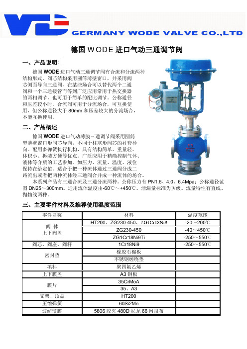
德国WODE 进口气动三通调节阀一、产品说明:德国WODE 进口气动三通调节阀有合流和分流两种结构形式。
阀芯结构采用圆筒薄壁窗口,并采用阀芯侧面导向三通阀,在某些场合可以替代两个二通阀和一个三通接管而等到广泛应用常用于热交换器的两相调节,也可用于简单的配比调节。
公称通径和压差较小时,合流阀可用于分流场合,可互换使用,但公称通径大于80mm 和压差较大的分流场合,不能互换使用。
二、产品概述德国WODE 进口气动薄膜三通调节阀采用圆筒型薄壁窗口形阀芯导向,不同于柱塞形阀芯的衬套导向。
配用多弹簧执行机构,具有结构简单、重量轻、体积小、拆装方便等优点。
广泛应用于精确控制气体、液体等介质的工艺参加。
如压力、流量、温度、液位保持在给定值。
适合于把一种流体通过三通阀分成二路流出或者把两种流体经三通阀合并成一种流体的场合。
本系列产品有三通合流及三通分流两种。
公称压力有PN1.6、4.0、6.4Mpa ;公称通径范围DN25~300mm 。
适用流体温度由-60℃~+450℃。
泄漏量标准为Ⅳ级。
流量特性有直线、抛物线两种。
三、主要零件材料及推荐使用温度范围 零件名称 材料 温度范围HT200、ZG230-450、ZG1Cr18Ni9 -20~200℃ ZG230-450 -40~450℃ 阀 体 上下阀盖 ZG1Cr18Ni9Ti -250~550℃阀芯、阀座、阀杆 1Cr18Ni9 -250~550℃橡胶石棉板 密封垫 不锈钢缠绕垫填料 聚四氟乙烯上下膜盖 A3钢板35CrMoA 膜片 35、A3支架、顶盘 HT200 压缩弹簧 60Si2Mn 波纺薄膜 5806胶夹480D 尼龙66网眼布四、主要技术参数和性能指标 1、调节机构主要技术参数合流 25 32 40 50 6580100 125150 200 250300 阀座直径mm 分流 25 32 40 50 6580100 125150 200 250300合流 8.5 13 21 34 5285125 210340 535 8001260 额定流量 系数kv 分流 25 32 40 50 6585125 210340 535 8001260 公称压力Mpa 1.6、4.0、6.4行 程mm 16 25 40 60 100 流量特性 直线介质温度℃ -20~200、-40~+250(常温型)、-40~315(中温型) 法兰尺寸 铸铁法兰尺寸按JB79-59,铸钢法兰尺寸按JB79-59法兰型式 法兰密封面型式按JB77-59,其中铸钢法兰按光滑式,铸钢法兰按凹式 阀体材质 HT200,ZG230-450、ZG1Cr18Ni9阀芯材质 1Cr18Ni9上阀盖型式 普通式(常温型)、热片式(中温型)可调比 30:1气源接头 M16×1.52、执行机构主要技术参数型 号 ZHA(B)-3 ZHA(B)-4 ZHA(B)-5 ZHA(B)-6 有效面积cm2 400 630 1000 1600 行 程mm 16.25 40 60 1000 弹簧范围KPa 20~100;40~200、20~60、60~100、80~2403、性能指标项目 不带定位器 带定位器基本误差% ±6 ±1.5回差% 5 1.5死区% 4 0.6始点 ±2.5 气关 终点 ±6.0 始点 ±6.0 始终点偏差% 气开 终点 ±2.5±1.5 额定行程偏差% ±2.5允许泄漏量L/h 10-3×阀额定容量注:一般均应带定位器4、允许压差供气压力 弹簧压力25 32 40506580100125 150 200 2503000.14MPa 20-100 1220 750500300300200120120 80 50 5025可配附件:定位器、手轮机构、空气过滤减压器等。
- 1、下载文档前请自行甄别文档内容的完整性,平台不提供额外的编辑、内容补充、找答案等附加服务。
- 2、"仅部分预览"的文档,不可在线预览部分如存在完整性等问题,可反馈申请退款(可完整预览的文档不适用该条件!)。
- 3、如文档侵犯您的权益,请联系客服反馈,我们会尽快为您处理(人工客服工作时间:9:00-18:30)。
气动三通球阀说明书:
一、气动三通球阀产品概述:
1、结构紧凑、启闭迅速、流道畅通、流体阻力小。
2、密封性能好:利用四面阀座材料聚四氟乙烯弹性变形实现无泄漏密封。
3、一阀多用:任一通口可用作入口而无泄漏,三通既可制成L型通口,也可制成T型通口。
4,维修方便:在系统卸压后,无需拆下整个阀体就可进行检查和维修。
5、泛适用于供水、石化、冶金、矿山、轻纺、能源、造纸、食品、钢铁等管路系统中对介质流向进行切换以及对介质的分流或混合流体。
二、气动三通球阀介质流向原理:
气动三通球阀分L型和T型,介质流通方向见下图。
L型三通球阀适用于介质流向的切换,能使相互垂直的两个通道连通:T型三通球阀适用于介质的分流、合流或流向切换,T型孔道可以使三个通道互相连通或使其中两个通道连通,三通球阀一般采用两个阀座结构,亦可根据用户要求采用四阀座结构。
三、气动三通球阀执行标准:
I 设计和制造:GB/T12237-1989; APl608。
2.检验和试验:GB/T13927-1992; APl 598。
3 法兰连接:JB/T79]一2-1994; ASME/ANSI B165。
4 结构长度:JD-2002
产品实拍:
附件选项:根据不同控制和要求可选择下列附件:
回讯器:也叫限位开关,远程反馈开关信号(可选防爆)。
电磁阀:双作用选二位五通、单作用选二位三通(可选防爆)。
三联件:可对气源稳压、过滤、气缸加润滑油。
手轮机构:转动手轮机构,可实现手动开、关阀。
电气定位器:输入4~20mA信号,实现阀门调节功能。
四、气动三通球阀试验压力:
五、气动三通球阀使用范围:。