Murata NF Series-202898
Murata Power Solutions MP-HW80EVAL-01评估板用户指南说明书

MP-HW80EVAL-01MP-HW80EVAL-01Analog DC-DC Evaluation BoardUser GuidePRELIMINARY1.IntroductionMP-HW80EVAL-01 Evaluation Board User GuideThe MP-HW80EVAL-01 Evaluation Board is designed to assist with the evaluation of the IRH-W80, 250W, 10:1input range DC/DC converter module from Murata Power Solutions. The IRH-W80 series of isolated regulatedconverter modules, deliver an impressive 250W single output from a wide input range of 16V – 160Vdc, complyingwith the input battery voltage transient range of EN50155.The half brick module offers high efficiency levels up to 90%, with an input – output isolation voltage of 4242Vdc.The module features Overvoltage, Overcurrent, Short Circuit, Adjustable output voltage, Adjustable Current Limit,Positive or Negative Logic enable, Pulse output signal and Hold up function for an external capacitor. See Page 10for full schematic.Figure 1 – Evaluation BoardMP-HW80EVAL-01Analog DC-DC Evaluation BoardUser GuidePRELIMINARY2.Setup2.1 ConnectionsThis section describes the connector locations/pinouts on the evaluation board, to enable correct set up.Figure 2 - Connectors Position / Resistor Functions (Top View)H1 Input Voltage ConnectorH2 Signal Connector Resistor / Function Pin 1 VIN- Pin 1 PULSE R1 UVLOPin 2 VIN- Pin 2 VIN- R2 TRIM DOWNPin 3 VIN+ Pin 3 ON/OFF R3 TRIM UPPin 4 VIN+ Pin 4 PE R4 CHARGER5 SENSE (+) H3 Output Voltage Connector H4 External Hold Up Connector R6 SENSE (-)Pin 1 VOUT- Pin 1 VIN- R7 OCPPin 2 VOUT- Pin 2 CHOLD+ R1, R2, R3, R5, R6, R7 = SMD0805 Pin 3 VOUT+Pin 4 VOUT+MP-HW80EVAL-01Analog DC-DC Evaluation BoardUser GuidePRELIMINARY2.2 On Board Component Values2.2.3 OCP Resistor ValueR7 = OCP – Overcurrent Protection.By adding a resistor SMD0805 to position R7 on the PCB, it is possible to set the overcurrent threshold point.Leave unconnected if not used.Figure 3 - OCP Resistor SelectionR7 OCP Value 562Ω 665Ω 845Ω 1.13kΩ 1.69kΩ 3.32kΩ 6.65kΩ 10kΩ Open 24Vin 14.5A 16.2A 18.2A 20.2A 22.4A 24.3A 25A 25.5A 26A48Vin 15.5A 17.4A 19.4A 21.1A 23A 24.5A 25.4A 25.9A 26.5A72Vin 15.5A 17.4A 19.4A 21.1A 23A 24.5A 25.4A 25.9A 26.5A110Vin 11.6A 14A 17.1A 19.8A 22.1A 24.5A 25.4A 25.8A 27A2.2.4 Under Voltage Lockout. (UVLO)By adding a SMD0805 resistor to R1 position as per the table below, the converter will shut down if the inputvoltage drops below the threshold. The converter will automatically restart when the input voltages rises above theUVLO threshold. Leave unconnected if not used.Figure 4 - UVLO Resistor Value TableVin 24V 36V 48V 72V 96V 110VTurn Off 10V-12V 17.5V-19.5V 26V-28V 40V-43V 56V-60V 65V-70VTurn On 13V-15V 22V-24V 31V-34V 48V-51V 68V-72V 80V-84VResistor Value Open 27.4kΩ 13kΩ 6.8kΩ 4.3kΩ 3.57kΩ2.2.5 Output Voltage Trim ResistorsR3 and R2 – Trimming the Output Voltage.The trim pin of the converter allows the user to adjust the output either +10% or -20% by using SMD0805fixed value resistors.Figure 5 - Output Trim Resistor Values12V OutputOutput Voltage 9.6V 10.8V 11.4V 12.6V 13.2VR3 - Trim Up NA NA NA 188kΩ 97kΩR2 - Trim Down 4kΩ 8.9kΩ 18.7kΩ NA NAMP-HW80EVAL-01Analog DC-DC Evaluation BoardUser GuidePRELIMINARY2.2.6 Sense ConnectionsIf intended to utilize the output sense feature, please ensure that you short out, or add a zero ohm link in positionsR5, Sense (+) and R6, Sense (-). If it is proposed to use the sense function, then please leave R5 and R6 opencircuit, and connect output sense lines to the load. The sense connections can compensate up to 0.5V voltage dropof output leads.Figure 6 - Remote Sense Connection2.2.7 Hold Up CircuitThe BUS pin of the IRH250W80 module, is a voltage source output of 80Vdc to allow external capacitors to be connected in order to provide hold up power of the converter. The eval board houses a resistor (R4) to slowlycharge the capacitors up, and a feed forward diode (D1) for rapid discharge into the module during hold up mode.The capacitor value can be as per the below table to provide 10msec or 20msec of hold up. Connect the capacitorto H4 Pin 1 = VIN-, Pin 2 = CHOLD+. As per Figure 2.Figure 7 - Hold-Up Capacitor ValuesHold-up time 24Vin36Vin 48Vin 72Vin 96Vin 110Vin 10ms 2200uF 2200uF 2200uF 2200uF 1100uF 700uF20ms 4400uF 4400uF 4400uF 4400uF 2200uF 1400uF2.2.8 External FusingThe evaluation board does not have any fusing protection, the user must provide external fusing, circuit breaker protection as required.MP-HW80EVAL-01Analog DC-DC Evaluation BoardUser GuidePRELIMINARY2.2.9 Pulse OutThis pin outputs a 1kHz 50% duty cycle pulse voltage with 12V amplitude. It is designed to provide a bootstrapsignal for the input inrush current limit circuit and could also indicate operating status with a LED connected.Leave unconnected if not used.2.2.10 On/Off ControlConnect the On/Off pin (Pin 3, H2) to -VIN (Pin 2, H2) connection if “Negative” logic level is used in the part numberof the IRH-W80. Leave the On/Off pin open if “Positive” logic level is used.Note: A mechanical On/Off switch is also provided on the top side of the evaluation board.MP-HW80EVAL-01Analog DC-DC Evaluation BoardUser GuidePRELIMINARY3. EMI CircuitThe following schematic below meets EN55011 Class A.Figure 8 - EMI SchematicFigure 9 - EMI BOMReference Manufacturer MPN Type Specifications QtyMOV1 Epcos B72214S0141K101 Varistor 180V, 36J 1TVS1 Littel Fuse 1.5KE220A TVS diode 185V, 1.5KW 1C1 Faratronic C212E475K9AC000 Polyester capacitor 250V, 4.7uF 1C2, C3, C4 Murata GRM43DR72E474KW01L Capacitor MLCC 250V, 0.47uF 3C5, C6, C11, C12, C13, C14 Murata DE1E3RA102MA4BQ01F Safety ceramic cap 500V, 1000pF 6C9, C10 NCC EKXJ251EXX271ML40S E-cap 250V, 270uF 2C15, C16 Murata DE1E3RA472MA4BQ01F Safety ceramic cap 500V, 4700pF 2L1 Wurth 7448262013 CM choke 1.3mH, 20A 1L2, L3 Bourns 2300HT-220-V-RC1951 DM choke 22uH, 19A 2C7, C8 NA NOT USED NA NA 0C17, C18 NA NOT USED NA NA 0MP-HW80EVAL-01Analog DC-DC Evaluation BoardUser GuidePRELIMINARYFigure 10 - EMI ResultsLimit Line as per EN55011 level AVin = 110V, Line LMP-HW80EVAL-01Analog DC-DC Evaluation BoardUser GuidePRELIMINARY4. Circuit SchematicMP-HW80EVAL-01Analog DC-DC Evaluation BoardUser GuidePRELIMINARY5. Mechanical Drawings / Dimensions3: UNIT WEIGHT = 690 gramsMP-HW80EVAL-01 Analog DC-DC Evaluation Board User GuideDCAN-70_MP-HW80EVAL-01_A01.D08 Page 12 of 12PRELIMINARY6. Packaging InformationMurata Power Solutions, Inc.129 Flanders Rd., Westborough, MA 01581 USAISO 9001 and 14001 REGISTERED This product is subject to the following operating requirements and the Life and Safety Critical Application Sales Policy : Refer to: /requirements/Murata Power Solutions, Inc. makes no representation that the use of its products in the circuits described herein, or the use of other technical information contained herein, will not infringe upon existing or future patent rights. The descriptions contained herein do not imply the granting of licenses to make, use, or sell equipment constructed in accordance therewith. Specifications are subject to change w ithout notice. © 2021 Murata Power Solutions, Inc.MP-HW80EVAL-01。
意大利进口锐无敌锯片总目录

复合材料、胶 合板-优秀
LU3C 双贴面板材切割 锯片
LU3D 双贴面板材切割 锯片
LU3E 双贴面板材切割 锯片
LU3F 双贴面板材切割 锯片
LSA 硬质合金裁板锯 锯片 LSB 硬质合金裁板锯 锯片
LSC 硬质合 金”SUPERCUT” 裁板锯锯片
切割双贴面刨花
板,不需划槽锯片
LU2D 实木、复合材料 切割锯片
LU2E 实木、复合材料 切割锯片
LU2F 木板、木质复合 材料及硬质塑料 切割锯片
LU3A 双贴面板材切割 锯片
LU3B 双贴面板材切割 锯片
纵切横截锯片,多 数采用降音减震设 计,大大提高锯切 质量。 纵切横截锯片,多 数采用降音减震设 计,大大提高锯切 质量。
软、硬木
含水率高于 10%的软、硬木 和长纤维木料
软、硬木
含水率小于 10%品质好的软 硬木。
切割软硬木好
切割软硬木好
切割软硬木好 切割软硬木好 切割软硬木好
切割软硬木好
切割软硬木好
切割软硬木好
切割软硬木好
切割软硬木好
LM08R 钛涂层超薄多片 锯
LU1A 摇臂式、转向式 锯机用锯片 LU1B 工业用合金锯片
LU1C 实木切割锯片
LU1D 实木切割锯片
LU1E 实木切割锯片薄锯路 LU1F 实木切割锯片薄锯路
LU1G 实木切割锯片
LU1H 实木切割锯片薄锯路
LU1I 实木、镜框切割 锯片
LU1L 实木画框、镜框
纵切,超薄锯路设 计大大减少材料的 浪费。不能扩孔或 重开。不需要经常 清洁锯片
横切
纵切横截锯片
硬质双贴面板
双面漆面板和 双面木皮饰面 板。
SCA103T数据手册
Features
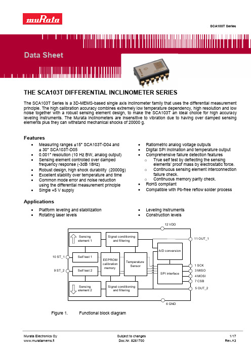
Measuring ranges ±15° SCA103T-D04 and ± 30° SCA103T-D05 0.001° resolution (10 Hz BW, analog output) Sensing element controlled over damped frequency response (-3dB 18Hz) Robust design, high shock durability (20000g) Excellent stability over temperature and time Common mode error and noise reduction using the differential measurement principle Single +5 V supply Ratiometric analog voltage outputs Digital SPI inclination and temperature output Comprehensive failure detection features o True self test by deflecting the sensing elements’ proof mass by electrostatic force. o Continuous sensing element interconnection failure check. o Continuous memory parity check. RoHS compliant Compatible with Pb-free reflow solder process
2 Functional Description .......................................................................................................8
布恩商业用品部分部件目录说明书

JDF-2S/N 0005473 & UPILLUSTRATED PARTS CATALOG Designs, materials, weights, specifications, and dimensions for equipment or replacement parts are subject to change without notice.BUNN-O-MATIC CORPORATION POST OFFICE BOX 3227SPRINGFIELD, ILLINOIS 62708-3227PHONE: (217) 529-6601 FAX: (217) 529-664438311.0000E 03/08 ©2005 Bunn-O-Matic Corporation DISCONTINUED VERSION Parts listed in this catalog may no longer be available.BUNN-O-MATIC COMMERCIAL PRODUCT WARRANTYBunn-O-Matic Corp. (“BUNN”) warrants equipment manufactured by it as follows:1) All equipment other than as specified below: 2 years parts and 1 year labor.2) Electronic circuit and/or control boards: parts and labor for 3 years.3) Compressors on refrigeration equipment: 5 years parts and 1 year labor.4) Grinding burrs on coffee grinding equipment to grind coffee to meet original factory screen sieve analysis: parts and labor for 3 years or 30,000 pounds of coffee, whichever comes first.These warranty periods run from the date of installation BUNN warrants that the equipment manufactured by it will be commercially free of defects in material and workmanship existing at the time of manufacture and appearing within the applicable warranty period. This warranty does not apply to any equipment, component or part that was not manufactured by BUNN or that, in BUNN’s judgment, has been affected by misuse, neglect, alteration, improper installation or operation, improper maintenance or repair, damage or casualty. This warranty is conditioned on the Buyer 1) giving BUNN prompt notice of any claim to be made under this warranty by telephone at (217) 529-6601 or by writing to Post Office Box 3227, Springfield, Illinois 62708-3227; 2) if requested by BUNN, shipping the defective equipment prepaid to an authorized BUNN service location; and 3) receiving prior authorization from BUNN that the defective equipment is under warranty.THE FOREGOING WARRANTY IS EXCLUSIVE AND IS IN LIEU OF ANY OTHER WARRANTY, WRITTEN OR ORAL, EXPRESS OR IMPLIED, INCLUDING, BUT NOT LIMITED TO, ANY IMPLIED WARRANTY OF EITHER MERCHANTABILITY OR FITNESS FOR A PARTICULAR PURPOSE. The agents, dealers or employees of BUNN are not authorized to make modifications to this warranty or to make additional warranties that are binding on BUNN. Accordingly, statements by such individuals, whether oral or written, do not constitute warranties and should not be relied upon.If BUNN determines in its sole discretion that the equipment does not conform to the warranty, BUNN, at its exclusive option while the equipment is under warranty, shall either 1) provide at no charge replacement parts and/or labor (during the applicable parts and labor warranty periods specified above) to repair the defective components, provided that this repair is done by a BUNN Authorized Service Representative; or 2) shall replace the equipment or refund the purchase price for the equipment.THE BUYER’S REMEDY AGAINST BUNN FOR THE BREACH OF ANY OBLIGATION ARISING OUT OF THE SALE OF THIS EQUIPMENT, WHETHER DERIVED FROM WARRANTY OR OTHERWISE, SHALL BE LIMITED, AT BUNN’S SOLE OPTION AS SPECIFIED HEREIN, TO REPAIR, REPLACEMENT OR REFUND.In no event shall BUNN be liable for any other damage or loss, including, but not limited to, lost profits, lost sales, loss of use of equipment, claims of Buyer’s customers, cost of capital, cost of down time, cost of substitute equipment, facilities or services, or any other special, incidental or consequential damages.BrewWISE, BUNN Gourmet Ice, BUNN Pour-O-Matic, BUNN, Bunn-OMatic, Bunn-O-Matic, BUNNlink, BUNNserve, BUNN Espress, DBC, Dr. Brew, Dual, EasyClear, EasyGard, Easy Pour, FlavorGard, Gourmet Ice, Gourmet Juice, High Intensity, IMIX, Infusion Series, Legendary for Quality, The Mark of Quality in Beverage Equipment Worldwide, My Café, Power-Logic, Safety-Fresh, Scale-Pro, Single, Smart Funnel, Smart Hopper, Soft Heat, SplashGard, System III, ThermoFresh, 392, AXIOM, Beverage Profit Calculator, Beverage Bar Creator, BrewLOGIC, BrewMETER, BrewWIZARD, BUNNSERVE, BUNNsource, Coffee At Its Best, Cool Froth, Digital Brewer Control, Intellisteam, Nothing Brews Like a BUNN, Pouring Profits, Pulse Wave, Quality Beverage Equipment Worldwide, Signature Series, Silver Series, Smart Heat, SmartWAVE, Tea At Its Best, The Horizontal Red Line, Titan, Ultra, are either trademarks or registered trademarks of Bunn-O-Matic Corporation.238311 020608TABLE OF CONTENTSMain Frame & Covers (4)Upper Cabinet & Panels (6)Refrigeration Components (8)Compressor Components (10)Fan Assembly (12)Water Tank Assy (14)Circulation Pump & Lines (18)Product Coil & Lines (20)Dispense Platform Assy (22)Dispense Valve Assy (24)Plain Water Manifold (Early Models) (26)Plain Water Manifold (Late Models) (28)Rinse Water Manifold & Solenoid (Early Models) (30)Rinse Water Manifold & Solenoid (Late Models) (34)Pump Assy (38)Bottle Adapter Assy (40)Door Assy (42)Electrical Components (46)Refillable Container Assy (50)Numerical Index (52)338311 111706438311 050807ITEM PART NO. QTY. DESCRIPTION5* Indicates the part number listed is for reference only. See DESCRIPTION for possible service replacement.MAIN FRAME & COVERS1 34409.0000 1 Base Frame Assy2 26528.0000 4 Leg 03996.0000 4 Pad, Non-skid3 34410.0000 1 Frame, Refridgeration - - - - - - - -4 Screw #10-32 x4 39428.0000* 2Bracket, Rear support (Late models with Water Inlet Valve)34797.0000* 2 Bracket, Rear support (Early models prior to Water Inlet Valve) 02332.0001 8 Screw, Crimptite #6 x .25"5 38469.0001* 1 Bracket, Upper Frame6 36192.1000 1 Panel w/Decals, Right (Includes item 11) 02332.0001 3 Screw, Crimptite #6 x .25"7 34786.1000 1 Panel w/Decals, Top (Includes item 8) 02332.0001 4 Screw, Crimptite #6 x .25"8 33458.0000 1 Decal, Refridgeration ON - OFF9 36191.1000 1 Panel w/Decals, Left (Includes items 10, 11, 12 & 24) 02332.0001 3 Screw, Crimptite #6 x .25"10 33461.0001 1 Decal, Refridgerant Charge11 27442.0000 2 Decal, Warning - Moving Parts12 00986.0002 1 Decal, Warning - Electrical13 39561.0001 1 Panel, Rear 02332.0001 4 Screw, Crimptite #6 x .25"14 33645.0000 1 Decal, Main Water Connection15 33646.0000 1 Decal, Rinse Water Connection (Early Models)16 00656.0000 1 Decal, Comply To Plumbing Code17 27354.0000 4 Bushing18 00668.0000 3 Plug19 35998.0001 1 Panel, Splash 01317.0003 2 Screw, Truss Head, Locking #8-32 x .38"20 21436.0000 2 Catch, Magnetic21 33538.0000*1 Bracket, Right33539.0000* 1 Bracket, Left 01311.0001 4 Screw, Truss Head, Locking #8-32 x .25"22 38765.1000 1 Drip Tray Assy (Includes strike plate and item 23)23 26801.0000 1 Grate, Drip Tray24 35277.0000 1 Schematic, Electrical38311 121207638311 111706ITEM PART NO. QTY. DESCRIPTION7* Indicates the part number listed is for reference only. See DESCRIPTION for possible service replacement.UPPER CABINET & PANELS1 35478.0000* 1 Cabinet (Not serviced) 24544.0000 10 Screw, Pan Head #8-182 34738.0000 1 Plate, Cabinet Mounting 01311.0001 4 Screw, Truss Head #8-32 x .25" Lkg.3 34784.0000 1 Plate, Bottom Closure 01359.0000 3 Screw, Flat Head #8-32 x .38"4 34362.0000 1 Bushing, Lower Hinge5 34790.0000 1 Wrap 01311.0001 4 Screw, Truss Head #8-32 x .25" Lkg.6 34785.0000* 1 Bracket, Hinge 01327.0000 3 Screw, Pan Head #10 -32 x .38"7 34666.0001 1 Catch, Door Latch 01382.0000 2 Screw, Truss Head #6 x .375"8 27394.0000 2 Plug9 00669.0002 4 Plug10 34419.0000 1 Coil, Water 24544.0000 4 Screw, Pan Head #8-1811 27246.0000 1 Sensor Assy, Temperature12 33669.0000 1 Clip, Adhesive Back13 33297.0000 1 Fan Assy. 03290.0000 1 Cable Tie 38616.0000 4 Screw, Pan Head #8-1814 34421.0000* 1 Cover, Fan 24544.0000 4 Screw, Hex Head w/Washer #10-2415 34422.1000 1 Shelf, Product (Includes items 16 & 17)16 33459.0003 2 Decal, Dispense/Rinse17 32461.0000 2 Gasket, Drip18 32455.0000 2 Knob19 27394.0000 2 Plug20 35930.0000 2 Nozzle21 32848.0000 2 O-ring22 35108.1000 2 Mixer, Spiral23 38519.0000 1 Decal, Dispense Ratio24 M2568.1000 - Grease, USDA H-1 (Use when assembling items 21 & 22)38311 121207838311 062905ITEM PART NO. QTY. DESCRIPTION9* Indicates the part number listed is for reference only. See DESCRIPTION for possible service replacement. 1 35164.1000 1 Air Filter2 29951.0001 1 Condenser 02335.0001 4 Screw, Crimptite #8 x .38"3 35180.0001 1 Tube (Requires brazing to install) (Not serviced)4 35386.0001 1 Tube (Requires brazing to install) (Not serviced)5 00396.0002 1 Tee (Requires brazing to install) (Not serviced)6 35385.0001 1 Tube (Requires brazing to install) (Not serviced)7 35580.0001 1 Tube (Requires brazing to install) (Not serviced)8 35175.1000 1 Filter Dryer Assy (Requires brazing to install)9 35179.0001 1 Tube (Requires brazing to install) (Not serviced)10 32776.0000 1 Accumulator11 35581.0001 1 Tube (Requires brazing to install) (Not serviced)12 - - - - - - - - 1 Compressor (See COMPRESSOR COMPONENTS) 34529.0000* 4 Washer 00901.0000 4 Nut .25"-2013 - - - - - - - - 4 Grommet14 - - - - - - - - 4 Sleeve 15 33536.0000 1 Platform 01317.0003 4 Screw, Truss Head, Locking #8-32 x .38"16 - - - - - - - - 1 Fan Assy (See FAN ASSEMBLY) 27243.0000 3 Screw #8-36 x .437"17 34418.0000* 1 Bracket 01317.0003 4 Screw, Truss Head, Locking #8-32 x .38"18 28567.0000 1 Mounting Kit (Includes four each of items 13 & 14)19 M2332.1000 - Insulation, Tube 25/50 - 1.6"ID x .50" wall x 6.0 Ft (Use as required) 20 M2336.1000 - Insulation, Tube 25/50 - 0.25"ID x .19" wall x 6.0 Ft (Use as required)REFRIGERATION COMPONENTSOrder item 1838311 0303081038311 111706ITEMPART NO.QTY.DESCRIPTION11* Indicates the part number listed is for reference only. See DESCRIPTION for possible service replacement.COMPRESSOR COMPONENTS- 38231.1000 1 Compressor 120V (Includes items 1 - 5) 33522.1001 1 Compressor 230V (Includes items 1 - 5) 1 38897.0000 1 Relay, Compressor 120V 38897.0001 1 Relay, Compressor 230V 2 38917.0000 1 Overload Protector 3 38916.0000 1 Retainer 4 38918.0000 1 Clip 538896.00001Cover38311 1117061238311 062905ITEMPART NO.QTY.DESCRIPTION13* Indicates the part number listed is for reference only. See DESCRIPTION for possible service replacement.FAN ASSEMBLY- 32204.1001 1 Fan Assy 120V (Includes items 1-4) 32204.1002 1 Fan Assy 230V (Includes items 1-4) 1 33603.0000 1 Motor Assy 120V 33603.0001 1 Motor Assy 230V 2 33602.0000 1 Blade, Fan 3 27258.0000 1 Silencer 423700.00001Nut .25"-2038311 0629051438311 111706ITEMPART NO.QTY.DESCRIPTION15* Indicates the part number listed is for reference only. See DESCRIPTION for possible service replacement.WATER TANK ASSY1 35165.0000 1 Tank Assy - - - - - - - - 4 Screw2 35272.1001 1 Lid Assy 24544.0000 6 Screw, Pan Head #8-183 35526.0000* 2 Bracket 02332.0001 2 Screw, Crimptite #6 x .25" 01317.0003 2 Screw, Truss Head, Locking #8-32 x .38"4 34403.1001 1 Panel Assy 00973.0000 4 Nut, Keps #6-325 33801.0000 1 Grommet6 29327.0000 1 Probe, Temperature & Dry Plug7 33801.0002 1 Grommet 7 02536.0000 1 Grommet9 02645.1000 1 Probe, Liquid Level 01522.0000 1 Washer 20203.0100 1 Lockwasher, Internal-tooth #800908.0000 1 Nut #8-32 10 21275.0004 3 Clamp .54" - .64"11 20976.0062* 1 Tube, Silicone .38" ID x 1.75" (Order item 35) 1221275.0005 1 Clamp .62" - .73" 120V 21275.0009 1 Clamp .65" - .78" 230V 13 35077.0000 1 Tee .38" Sngl. Barb 14 21275.0003 4 Clamp .57" - .70"15 34325.0003* 1 Hose, Flex .38" ID x .625" OD x 3.0" (Order item 36) 16 33623.0000 2 Elbow .38" Barb17 34325.0006* 1 Hose, Flex .38" ID x .625" OD x 2.25" (Order item 36) 18 20976.0016* 1 Tube, Silicone .38" ID x 2.75" (Order item 35) 19 33068.0000 1 Fitting .38" Barb x .25" Barb20 37809.1000 1 Pump Assy 120V (Includes items 11 - 19) 37265.0000 1 Pump Assy 230V 21 35132.0000* 1 Product Coil22 34416.0000 2 Spacer 00973.0000 4 Nut, Keps #6-32 23 03290.0000 2 Cable Tie 2432734.00016Cable Tie, 28.0"(Continued)38311 0508071638311 111706ITEMPART NO.QTY.DESCRIPTION17* Indicates the part number listed is for reference only. See DESCRIPTION for possible service replacement.WATER TANK ASSY25 33533.0000* 4 Spacer 26 33519.0000* 1 Evaporator Coil 27 36448.0000 2 Spacer 28 03290.0000 2 Cable Tie29 33670.0004* 1 Tube, Clear .25" x 8.0" (Not serviced) 30 38605.0000 1 Tee31 21275.0006 1 Clamp .40" - .50" 32 35174.0000 1 Fitting 33 33149.0000 1 Gasket 34 00976.0000 1 Cap35 35106.0000 1 Manifold, Return Water36 20976.1000 1 Tube, Silicone .38" ID x 12.0" (Cut to required length) 20976.1001 1 Tube, Silicone .38" ID x 36.0" (Cut to required length) 20976.1002 1 Tube, Silicone .38" ID x 120.0" (Cut to required length) 37 34325.1000 1 Hose, Flex .38" ID x .625" OD x 12.0" (Cut to required length) 34325.1001 1 Hose, Flex .38" ID x .625" OD x 36.0" (Cut to required length)34325.10021Hose, Flex .38" ID x .625" OD x 120.0" (Cut to required length)38311 1117061838311 062905ITEMPART NO.QTY.DESCRIPTION19* Indicates the part number listed is for reference only. See DESCRIPTION for possible service replacement.1 - - - - - - - - 1 Coil, Upper Cabinet (See UPPER CABINET & PANELS)2 34325.0004* 2 Tube, Silicone .38" ID x 1.5" (Order item 10)3 21275.0003 8 Clamp .57" - .70"4 37850.0000 2 Elbow .38" Barb5 34325.0010* 1 Tube, Silicone .38" ID x 17.0" (Order item 10)6 34325.0021* 1 Tube, Silicone .38" ID x 8.0" (Order item 10)7 35173.0001 1 Fitting .312" Fl x .375" Barb8 35305.0000 1 Gasket9 - - - - - - - - 1 Manifold, Return Water (See WATER TANK ASSEMBLY) 10 34325.1000 - Tube, Silicone .38" ID x 12.0" (Cut to required length) 34325.1001 - Tube, Silicone .38" ID x 36.0" (Cut to required length) 34325.1002 - Tube, Silicone .38" ID x 120.0" (Cut to required length) 11M2337.1000-Tube Insulation (Cut to required length)CIRCULATION PUMP & LINES38311 1117062038311 111706ITEMPART NO.QTY.DESCRIPTION21* Indicates the part number listed is for reference only. See DESCRIPTION for possible service replacement.PRODUCT COIL & LINES1 - - - - - - - - 1 Product Coil (See WATER TANK ASSEMBLY)2 35305.0000 2 Gasket3 35173.0001 1 Fitting .312" Fl x .375" Barb4 21275.0003 8 Clamp .57" - .70"5 34325.0010* 1 Hose, Flex .38" ID x 17.0" (Order item 19)(Early models prior to Water Inlet Valve) 34325.0014* 1 Hose, Flex .38" ID x 15.0" (Order item 19)(Late models with Water Inlet Valve)6 33151.0004 1 Fitting, Elbow .38" Barb7 33149.0000 1 Gasket8 12757.0000 1 Nut9 01514.0000 1 Lockwasher 10 12756.0000 1 Fitting, Bulkhead11 35172.0001 1 Fitting, Elbow .312" Fl x .375" Barb 12 34325.0004* 1 Hose, Flex .38" ID x 1.5" (Order item 19) 13 37850.0000 1 Elbow .38" Barb14 34325.0012* 1 Hose, Flex .38" ID x 10.5" (Order item 19) 15 35171.0000 1 Valve, Shut Off 16 34540.0000 1 Decal, Caution - Close17 34325.0004* 1 Hose, Flex .38" ID x 1.5" (Order item 19) 18 34462.0000 1 Coupling, Quick Disconnect, Male19 34325.1000 1 Hose, Flex .38" ID x 12.0" (Cut to required length) 34325.1001 1 Hose, Flex .38" ID x 36.0" (Cut to required length) 34325.1002 1 Hose, Flex .38" ID x 120.0" (Cut to required length)20M2337.1000-Insulation, Tube 25/50 - 0.5"ID x .19" wall x 6.0 Ft (Use as required)38311 111706Early Models2238311 110107ITEMPART NO.QTY.DESCRIPTION23* Indicates the part number listed is for reference only. See DESCRIPTION for possible service replacement.DISPENSE PLATFORM ASSEMBLY1 38116.1000 1 Platform Assy (Includes items2 - 18) 2 - - - - - - - - 2 Pump Assy (See PUMP ASSY) 01338.0000 2 Screw, Truss Head #8-32 x .625" 01522.0000 4 Washer00991.0000 4 Nut, Elastic Lock #8-32 3 32957.0001 8 Bushing, Rubber 4 21275.0006 4 Clamp .40" - .50"5 38018.1000 2 Dispense Valve (See DISPENSE VALVE) 01308.0000 4 Screw, Truss Head #6-32 x 25"6 37786.0001 2 Plate 01308.0000 2Screw, Truss Head #6-32 x 25"7 - - - - - - - - 1 Manifold, Plain Water (See PLAIN WATER MANIFOLD) 8 - - - - - - - - 1 Manifold, Rinse Water (See RINSE WATER MANIFOLD) 9 32756.1000 2 Bottle Adapter (See BOTTLE ADAPTER) 01308.0000 4 Screw, Truss Head #6-32 x 25" 10 38122.0000* 1 Plate 01311.0001 4Screw, Truss Head #8-32 x .25" Lkg.11 32458.0000 2 Clip, Retainer 12 38104.0000 2 Thumbscrew 13 32454.0000 2 Fitting 1434087.00002O-ringThe following items are not illustrated 15 35189.0000 1 Harness, Dispense Platform 16 35181.0001 1 Harness, Dispense Valve 17 - - - - - - - - 4 Cable Tie (Not serviced) 1812422.00002Clamp38311 1101072438311 062905ITEMPART NO.QTY.DESCRIPTION25* Indicates the part number listed is for reference only. See DESCRIPTION for possible service replacement.DISPENSE VALVE ASSEMBLY- 38018.1000 1 Dispense Valve Assy (Includes items 1 - 24) 1 37801.0001 1 Body 2 37990.0000 1 Seal 3 37843.0000 1 Nozzle, Water4 32252.0000 1 Valve, Solenoid (Includes items5 - 10) 5 33554.0000 1 Solenoid Valve Coil6 28481.0000 1 Guide Kit (Includes Guide, Washer and O-ring)7 33585.0000 1 Solenoid Valve Base Kit (Includes O-ring and items 6 & 7) 8 01111.0002 1 Solenoid Valve Repair Kit (Includes Plunger, Spring and O-ring) 9 33580.0000 1 O-ring 10 33553.0000 1 O-ring11 37987.0000 1 Bracket 01308.0000 2 Screw #6-32 x .25" 12 32463.0000 1 Fitting, Elbow13 32849.0001 1 O-ring (Also use item 24) 14 37853.0000 1 Clamp 01308.0000 1 Screw #6-32 x .25" 15 32603.0000 1 Sleeve16 32852.0000 1 O-ring (Also use item 24) 17 32602.0000 1 Piston18 32853.0001 1 Spring, Flow Control 19 32624.0000 1 Bonnet, Adjuster 20 33725.0000 1 O-ring (Also use item 24) 21 32623.0000 1 Adjuster, Position 22 32851.0000 1 O-ring (Also use item 24) 23 37977.0000 1 Bracket, Water Adjustment 01308.0000 2 Screw #6-32 x .25"24M2568.1000-Grease, USDA H-1 (Use when assembling items 13,16,20 & 22)38311 1117062638311 111706ITEMPART NO.QTY.DESCRIPTION27* Indicates the part number listed is for reference only. See DESCRIPTION for possible service replacement.PLAIN WATER MANIFOLD (Early Models)1 32631.00002 Fitting, Straight 2 32849.0001 2 O-ring3 38129.0005* 2 Hose, Braided .25" ID x 2.25" (Order item 12)4 21275.0006 4 Clamp .40 - .50"5 36204.0000* 1 Manifold, Plain SST6 34325.0017* 1 Hose, Flex .38" ID x 1.25" (Order item 13)7 21275.0003 2 Clamp .57 - .70"8 34463.0000 1 Coupling, Quick Disconnect, Female12 38129.1000 1 Hose, Braided .25" ID x 12.0" (Cut to required length) 38129.1001 1 Hose, Braided .25" ID x 36.0" (Cut to required length) 38129.1002 1 Hose, Braided .25" ID x 120.0" (Cut to required length) 13 34325.1000 1 Hose, Flex .38" ID x 12.0" (Cut to required length) 34325.1001 1 Hose, Flex .38" ID x 36.0" (Cut to required length)34325.10021Hose, Flex .38" ID x 120.0" (Cut to required length)38311 1117062838311 111706ITEMPART NO.QTY.DESCRIPTION29* Indicates the part number listed is for reference only. See DESCRIPTION for possible service replacement.PLAIN WATER MANIFOLD (Late Models)38311 1117061 32631.00002 Fitting, Straight 2 32849.0001 2 O-ring3 38129.0012* 2 Hose, Braided .25" ID x 3.0" (Order item 8)4 21275.0006 6 Clamp .40 - .50"5 38605.0000 1 Tee .25" Barb6 38129.0013* 1 Hose, Braided .25" ID x 5.25" (Order item 8)7 34461.0000 1 Coupling, Quick Disconnect, Female8 38129.1000 1 Hose, Braided .25" ID x 12.0" (Cut to required length) 38129.1001 1 Hose, Braided .25" ID x 36.0" (Cut to required length)38129.10021Hose, Braided .25" ID x 120.0" (Cut to required length)3038311 111706RINSE WATER MANIFOLD & SOLENOID (Early Models) ITEM PART NO. QTY. DESCRIPTION1 32756.10002 Bottle adapter (See BOTTLE ADAPTER)2 38129.0001*3 Hose, Braided .25" ID x .44" OD x 1.50" (Order item 37)3 21275.0006 16 Clamp .40" - .50"4 36203.0000* 1 Manifold. Rinse SST5 34460.0000 1 Fitting, Quick Disconnect, Male6 34461.0000 1 Fitting, Quick Disconnect, Female7 32745.0021* 1 Hose .25" ID x .44" OD x 15.75" (Order item 38)8 33151.0005 3 Fitting, Elbow .25" Barb9 33149.0001 4 Gasket10 01085.0002 1 Solenoid Valve 120V (Includes items 11 - 14)28005.0000 1 Solenoid Valve 230V (Includes items 11- 13)01327.0000 2 Screw, Pan Head #10-32 x .38" 120V02308.0000 2 Screw, Pan Head #8-32 x .38" 230V11 28480.0000 1 Coil, Solenoid 120V28020.0000 1 Coil, Solenoid 230V12 01111.0002 1 Solenoid Repair Kit (Includes Plunger, Spring and O-ring)13 28479.0000 1 Solenoid Base Kit 120V (Includes O-ring)28021.0000 1 Core Assy Kit 230V14 28481.0000 1 Guide Kit15 00402.0001 2 Connector16 00425.0001 1 Nipple17 00425.0002 1 Nut18 38129.0001* 1 Hose, Braided .25" ID x .44" OD x 1.50" (Order item 37)19 00459.0000 1 Fitting, Bulkhead01532.0000 1 Lockwasher, Internal-toth .438"00463.0000 1 Nut, Hex .375"-2020 38129.0009* 1 Hose, Braided .25" ID x .44" OD x 4.25" (Order item 37)21 33149.0000 3 Gasket22 33151.0004 1 Fitting, Elbow .38" Barb23 21275.0003 4 Clamp .57" - .70"24 34325.0004* 1 Hose, Flex .38" ID x .595" OD x 1.5" (Order item 39)25 32749.0001 1 Tee .38" Barb x .38" Barb x .25" Barb(Continued)RINSE WATER MANIFOLD & SOLENOID (Early Models) ITEM PART NO. QTY. DESCRIPTION26 34325.0006* 1 Hose, Flex .38" ID x .595" OD x 2.25" (Order item 39)27 33150.0000 1 Nut28 33686.0000 1 Nipple29 23720.0000 1 Strainer Assy (Includes items 30 - 32)30 - - - - - - - - 1 Housing, Strainer (Order item 29)31 23721.0000 1 Screen32 23723.0000 1 End Cap33 21275.0006 2 Clamp .41 - .50"34 35573.0000* 1 Bracket, Rinse Solenoid (Early Models)01317.0003 2 Screw, Truss Head #8-32 x .38" Lkg35 32463.0000 2 Fitting, Elbow36 32849.0001 2 O-ring37 38129.1000 - Hose, Braided .25" ID x .44" OD x 12.0" (Cut to required length)38129.1001 - Hose, Braided .25" ID x .44" OD x 36.0" (Cut to required length)38129.1002 - Hose, Braided .25" ID x .44" OD x 120.0" (Cut to required length)38 32745.1002 - Hose .25" ID x .44" OD x 120.0" (Cut to required length)39 34325.1000 - Hose, Flex .38" ID x .595" OD x 12.0" (Cut to required length)34325.1001 - Hose, Flex .38" ID x .595" OD x 36.0" (Cut to required length)34325.1002 - Hose, Flex .38" ID x .595" OD x 120.0" (Cut to required length)ITEMPART NO.QTY.DESCRIPTIONRINSE WATER MANIFOLD & SOLENOID (Late Models)(Continued)1 32756.10002 Bottle adapter (See BOTTLE ADAPTER) 2 32849.0001 2 O-ring3 32463.0000 2 Fitting, Elbow4 38129.0009* 1 Hose, Braided .25" ID x 4.25" (Order item 40)5 21275.0006 8 Clamp .40" - .50"6 38129.0004* 1 Hose, Braided .25" ID x 3.50" (Order item 40)7 38605.0000 1 Tee .25" Barb8 38129.0001* 1 Hose, Braided .25" ID x 1.50" (Order item 40) 9 34460.0000 1 Fitting, Quick Disconnect, Male 10 34461.0000 1 Fitting, Quick Disconnect, Female11 32745.0021* 1 Hose .25" ID x 15.75" (Order item 39)(Early models prior to Water Inlet Valve) 38129.0014* 1 Hose .25" ID x 13.0" (Order item 40)(Late models with Water Inlet Valve) 12 01085.0002 1 Solenoid Valve 120V (Includes items 13 - 16) 28005.0000 1 Solenoid Valve 230V (Includes items 13- 15) 01327.0000 2 Screw, Pan Head #10-32 x .38" 120V02308.0000 2 Screw, Pan Head #8-32 x .38" 230V 1328480.0000 1 Coil, Solenoid 120V 28020.0000 1 Coil, Solenoid 230V14 01111.0002 1 Solenoid Repair Kit (Includes Plunger, Spring and O-ring) 15 28479.0000 1 Solenoid Base Kit 120V (Includes O-ring) 28021.0000 1 Core Assy Kit 230V 16 28481.0000 1 Guide Kit17 35573.0000* 1 Bracket, Rinse Solenoid (Early Models) 01317.0003 2 Screw, Truss Head #8-32 x .38" Lkg 18 00402.0001 1 Connector19 33151.0005 1 Fitting, Elbow .25" Barb 20 33149.0001 1 Gasket21 33152.0001 1 Fitting .38" Barb x .125" MPT22 34325.0022* 1 Hose, Flex .38" ID x 2.50" (Order item 41) 23 32750.0001 1 Tee .38" Single Barb24 34325.0021* 1 Hose, Flex .38" ID x 8.0" (Order item 41) 25 33686.0000 1 Nipple33150.00001NutRINSE WATER MANIFOLD & SOLENOID (Late Models) ITEM PART NO. QTY. DESCRIPTION26 21275.0003 5 Clamp .57" - .70"27 36203.0000* 1 Manifold. Rinse SST (Early Models)28 33149.0000 2 Gasket29 23720.0000 1 Strainer Assy (Includes items 30 - 32)30 - - - - - - - - 1 Housing, Strainer (Order item 29)31 23721.0000 1 Screen32 23723.0000 1 End Cap33 01533.0005 2 Spacer01326.0006 2 Screw, Truss Head #10-32 x .625"34 00464.0001 1 Elbow .25" Barb x .125"MPT35 34325.0004* 2 Hose, Flex .38" ID x 1.50" (Order item 41)36 35077.0000 1 Tee, Nylon .38" Barb37 36233.0000 1 Valve, Water Inlet 120V36233.0001 1 Valve, Water Inlet 230V32283.0000 2 Screw, Pan Head M4 x 6mm38 37297.0000 1 Elbow39 32745.1002 - Hose .25" ID x .44" OD x 120.0" (Cut to required length)40 38129.1000 - Hose, Braided .25" ID x .44" OD x 12.0" (Cut to required length)38129.1001 - Hose, Braided .25" ID x .44" OD x 36.0" (Cut to required length)38129.1002 - Hose, Braided .25" ID x .44" OD x 120.0" (Cut to required length) 41 34325.1000 - Hose, Flex .38" ID x .595" OD x 12.0" (Cut to required length)34325.1001 - Hose, Flex .38" ID x .595" OD x 36.0" (Cut to required length)34325.1002 - Hose, Flex .38" ID x .595" OD x 120.0" (Cut to required length)PUMP ASSEMBLYITEM PART NO. QTY. DESCRIPTION- 33803.1001 1 Pump Assy (Includes items 1 - 29)1 32613.1002 1 Motor Assy01322.0001 4 Screw #8-32 x 1.25"2 32654.0000 1 Magnet Hub01512.0000 1 Lockwasher, Internal-tooth #1001331.0004 1 Screw, Locking #10-32 x .50"3 33608.1000 1 Sensor, RPM02336.0000 2 Screw #4-40 x .38"4 07130.0000* 1 Cable Tie5 32957.0000 4 Bushing6 37152.0001 1 Mount Assy, Pump7 29904.0000 1 Insert, Well Nut #8-328 33781.0000 1 Gasket9 28755.0010* 1 Tube, Norprene .25" ID x 18.5" lg (Order item 17)10 32732.0000 1 Clamp .39"/.48"11 32656.0000 1 Fitting, Elbow .25" Barb x .38" Barb12 21275.0003 1 Clamp .57"/.70"13 34325.0019* 1 Hose, Flex .375" ID x 5.75" lg (Order item 18)14 28759.0000 1 Pump Assy. (Includes items 15 & 16)15 28794.0000 1 Rotor16 01370.0001 4 Screw, Pan Head #8-32 x 2.45"17 28755.1000 - Tube, Neoprene .25" ID x .45" OD x 12.0" (Use as required)28755.1001 - Tube, Neoprene .25" ID x .45" OD x 36.0" (Use as required)28755.1002 - Tube, Neoprene .25" ID x .45" OD x 60.0" (Use as required) 18 34325.1000 - Hose, Flex .375" ID x 12.0" (Use as required)34325.1001 - Hose, Flex .375" ID x 36.0" (Use as required)34325.1002 - Hose, Flex .375" ID x 120.0" (Use as required)19 39689.0000 - Pump Tube (Includes items 9,10,11,12 & 13)。
IKONICS Chroma Stencil Remover 285 用户指南说明书

An IKONICS Company | ISO 9001 Certifi ed | NASDAQ Listed: IKNX www.chromaline .com(800) 328-4261Follow us! WARNING: This product can expose you to chemicals including methanol, which is known in the State of California to cause birth defects or other reproductive harm. For more information go to C H R O M A L I N E S C RE E N C H E M I C A LCHOMA/STENCIL REMOVER™ 285Chroma/Stencil Remover™ 285 is a super concentratedliquid product formulated for the removal of all photosensi-tized emulsions. Especially suitable for automatic systems.APPLICATION Chroma/Stencil Remover 285 should be diluted with clean water, at a ratio of 1 part product to 20-40 parts water. Chroma/Stencil Remover 285 contains additives to aid in the complete removal of photosensitized emulsions from all types of screen mesh. CHARACTERISTICS Chroma/Stencil Remover 285 is a water-soluble colorlessliquid with no flash point. Product contains some acidsolutions and therefore is classified as corrosive. Chroma/Stencil Remover 285 quickly and easily dissolves allphotosensitized emulsions and rinses away completely.USEAGE INSTRUCTIONS For manual application, apply the Chroma/Stencil Remover285 solution to both sides of the wet screen. Allowsolution to dissolve the emulsion. Scrub the stencil area onboth sides to aid in a more complete removal of thestencil. Rinse with high pressure water. No degreasingusually required, except when applying capillary films.To ensure the safe and proper use of Chroma/Screen Chemical products, always refer to the products of SDS before use.180731FOR TECHNICAL SERVICE Call Toll Free: 1-800-328-4261Email: *******************(Outside North America Call +1-218-628-2217)。
ARTISAN TECHNOLOGY GROUP 设备购买和维修服务说明

MPT SERIESFax (406) 587-4911INTERNAL JUMPER SELECTIONSensor Type: Factory default is for operation with Thermistors, RTD, or LM335. If you are using an AD590, move the jumper from “ALL OTHERS” to “AD590”. An AD590 must be biased by at least +8V. If V+ exceeds +8V, it can be used for bias. Use pin 10 for the other AD590 connection, and do not connect pin 9. (See the Quick Connection diagram on page 3.)Sensor Current: The resistance of the sensor you choose, in conjunction with the sensor current, must produce a voltage between 0 V and 5 V in order to be used in the control loop. The 10 µA and 100 µA sensor currents are used with thermistors. The 1 mA sensor current is used with the LM335 IC Sensor and 500 or 1000Ω RTDs. The 10mA bias current (available on Rev. E) is for 100Ω RTDs.The voltage produced by your sensor is given by: V = R SENSOR * I SENSORCurrent Limit: Factory default is 0 A for the Current Limit Trimpot. Rotate this Trimpot clockwise to the desired maximum output current. The following charts detail the current limit settings available for each unit. PRODUCT REVISION CURRENT LIMIT TRIMPOT POSITIONSRev. G (Introduced 10/2014.)Tick Marks012345678 MPT25000A0.312A0.625A0.937A 1.25A 1.56A 1.87A 2.19A 2.5A MPT50000A0.4A1A 1.6A 2.2A 2.8A 3.75A 4.3A5A MPT100000A1A 2.5A 3.75A5A 6.25A7.75A8.75A10ARev. E (Introduced 9/2003.) &Rev. F(introduced 3/2005.)012345678910 MPT25000A250mA500mA750mA1A 1.25A 1.5A 1.75A2A 2.25A 2.5A MPT50000A500mA1A 1.5A2A 2.5A3A 3.5A4A 4.5A5A MPT100000A1A2A3A4A5A6A7A8A9A10ARev. D(Each setting represents a 20% increment of full scale current.)12345 MPT25000.5A1A 1.5A2A 2.5A MPT50001A2A3A4A5A MPT100002A4A6A8A10AProportional Gain: Measure resistance across the two test points labeled above to determine the gain setting. Factory default is a gain of 25.For MPT2500, Resistance = Gain * 4000; Default 100kΩFor MPT5000, Resistance = Gain * 2000; Default 51kΩFor MPT10000, Resistance = Gain * 1000; Default 25kΩMPT2500-00400-K © 2014 Wavelength Electronics, Inc. 6MPT2500-00400-K © 2014 Wavelength Electronics, Inc. 7A BCBBFIGURE AFIGURE B* All Other Tolerances are +/-5%MPT SERIES SELECTION GUIDE FIGMPT-2500 2.5 A Temperature Controller A MPT-5000 5 A Temperature Controller A MPT-1000010 A Temperature Controller B OPTIONAL ACCESSORIES AVAILABLE FOR SYSTEMDEVELOPMENT:CKT-202A connector kit includes the appropriate 15 pin D-sub connector, hood and hardware.WCB-101A Cable Kit includes one meter of cable soldered to a mating connector on one end and unterminated on the other.Precision thermistors for various temperature ranges areoffered with detailed R-T charts for quick system integration.MODEL R @ 25°C10 µA RANGE100 µA RANGETCS-605 5 k Ω- 55°C to - 2°C -20°C to +33°C TCS-61010 k Ω- 45°C to +13°C -8°C to +50°C TCS-10K510 k Ω- 45°C to +13°C -8°C to +50°C TCS-62020 k Ω- 35°C to +28°C +6°C to +69°C TCS-65050 k Ω- 18°C to +49°C +25°C to +92°CTCS-651100 k Ω- 6°Cto+67°C+41°Cto+114°CMPT2500-00400-K © 2014 Wavelength Electronics, Inc. 10Connector Kit CKT-202Cable KitWCB-101CAT-203 MPT I/O CABLECABL E #1CABL E #2RED/BLACK 2GREEN WHITE/BLACK WHITE BLUE WHITEBLACK BLUE ORANGE REDGREEN/BLACK ORANGE 1115131412109784563BLACK RED WIRE COLOR PIN 1GREEN 1111211211222CABLE #21Modulation Input Modulation GND (for pin 6)Temp Setpoint Monitor V+Temp MonitorMonitor GND (for 11 & 12)GND (For pins 7 & 8)V+Sensor +Sensor - (GND)TEC+TEC+TEC-TEC-FUNCTIONGND (For pins 7 & 8)WCB-101 MPT I/O CABLEArtisan Technology Group - Quality Instrumentation ... Guaranteed | (888) 88-SOURCE | 。
LT1930
123428fV IN , V OUT , SWA, SWB Voltage.......................–0.3 to 6V SWA, SWB Voltage, Pulsed, <100ns .........................7V SHDN, VC Voltage .........................................–0.3 to 6V FB Voltage ...................................–0.3 to (V OUT + 0.3V)Operating Temperature Range (Note 2)..–40°C to 85°C Storage Temperature Range..................–65°C to 125°CORDER PART NUMBER DD PART MARKING T JMAX = 125°C, θJA = 45°C/W,θJC = 3°C/WConsult LTC Marketing for parts specified with wider operating temperature ranges.LBBGABSOLUTE AXI U RATI GSW W WU PACKAGE/ORDER I FOR ATIOUUW (Note 1)ELECTRICAL CHARACTERISTICSNote 1: Absolute Maximum Ratings are those values beyond which the life of a device may be impaired.Note 2: The LTC3428E is guaranteed to meet performance specifications from 0°C to 70°C. Specifications over the –40°C to 85°C operatingtemperature range are assured by design, characterization and correlation with statistical process controls.The ● denotes the specifications which apply over the full operatingtemperature range, otherwise specifications are at T A = 25°C. V IN = 3.3V, V OUT = 5V unless otherwise noted.PARAMETERCONDITIONS MIN TYP MAX UNITSMinimum Startup Voltage 1.5 1.6V Quiescent Current, V OUT SHDN = V IN 100200µA Quiescent Current, V IN SHDN = V IN 1.32.0mA Shutdown Current SHDN = 0V 1µA Switching Frequency Per Phase ●0.8 1.0 1.2MHz FB Regulated Voltage ●1.2191.243 1.268V FB Input CurrentV FB = 1.24V150nA Error Amp Transconductance 170µS Output Adjust Voltage 1.65.25V NMOS Switch Leakage V SWA , V SWB = 5.5V, Per Phase 0.1 2.5µA NMOS Switch On Resistance V OUT = 5V, Per Phase 0.093ΩNMOS Current Limit Per Phase●2 2.5ASHDN Input Threshold ●0.40.8 1.5V SHDN Input Current 0.011µA Maximum Duty Cycle ●8087%Minimum Duty Cycle ●%Current Limit Delay to Output(Note 3)40nsNote 3: Specification is guaranteed by design and not 100% tested in production.Note 4: This IC includes overtemperature protection that is intended to protect the device during momentary overload conditions. Junctiontemperature will exceed 125°C when overtemperature protection is active.Continuous operation above the specified maximum operating junction temperature may impair device reliability.TOP VIEWDD PACKAGE10-LEAD (3mm × 3mm) PLASTIC DFN EXPOSED PAD MUST BE SOLDEREDTO GROUND PLANE ON PCB 10967845321PGNDB SWB V IN AGND FBPGNDA SWA V OUT SHDN V C11LTC3428EDD33428 G043428 G023428 G013428 G033428 G0710ns/DIV500ns/DIV500ns/DIV500ns/DIV100µs/DIVOutput Voltage Ripple with 22µF43428fPI FU CTIO SU U UPGNDA, PGNDB (Pins 1, 10, 11 (Exposed Pad)): Power Ground for the IC. Tie directly to local ground plane.SWB (Pin 2), SWA (Pin 9): Phase B and Phase A Switch Pins. The inductor and Schottky diodes for each phase are connected to these pins. Minimize trace length to reduce EMI.V OUT (Pin 3): Power Supply Output and Bootstrapped Power Source for the IC. Connect low ESR output filter capacitors from this pin to the ground plane.SHDN (Pin 4): Shutdown Pin. Grounding this pin shuts down the IC. Connect to a voltage greater than 1.5V to enable.TYPICAL PERFOR A CE CHARACTERISTICSU WP E A K C U R R E N T L I M I T (A )3.43.23.02.82.62.42.22.03428 G10TEMPERATURE (°C)–451555–25–5357595Peak Current Limit vs TemperatureV C (Pin 5): Error Amp Output. A frequency compensation network is connected to this pin to compensate the boost converter loop.FB (Pin 6): Feedback Pin. A resistor divider from V OUT is connected here to set the output voltage according to V OUT = 1.243 • (1 + R1 / R2)AGND (Pin 7): Signal Ground for the IC. Connect to ground plane near feedback resistor divider.V IN (Pin 8): Input Supply Pin. Bypass V IN with a low ESR ceramic capacitor of at least 4.7µF. X5R and X7R dielec-trics are preferred for their superior voltage and tempera-ture characteristics.56783428fTable 2. Capacitor Vendor InformationSupplier PhoneFaxWebsiteAVX (803) 448-9411(803) Sanyo (619) 661-9322(619) TDK (847) 803-6100(847) Murata(814) 237-1431(814) Taiyo Yuden (408) 573-4150(408) Output Diode SelectionFor high efficiency, a fast switching diode with low reverse leakage and a low forward drop is required. Schottky diodes are recommended for their low forward drop and fast switching times. When selecting a diode, it is important to remember that the average diode current in a boost converter is equal to the average load current: I D = I LOAD When selecting a diode, make sure that the peak forward current and average power dissipation ratings meet the application requirements. See Table 3 for a list of Schottky diode manufacturers. Example diodes are Philips PMEG1020, PMEG2010, On-Semi MBRA210, IR 10BQ015, Microsemi UPS120E, UPS315.Table 3. Diode Vendor InformationSupplier PhoneFaxWebsite Philips +31 40 27 Microsemi (949) 221-7100(949) On-Semi(602) 244-6600 International (310) 469-2161(310) RectifierThermal ConsiderationsTo deliver maximum power, it is necessary to provide a good thermal path to dissipate the heat generated within the LTC3428’s package. The large thermal pad on the IC underside can accomplish this requirement. Use multiple PC board vias to conduct heat from the IC and to a copper plane that has as much area as possible.APPLICATIO S I FOR ATIOW UUU If the junction temperature gets too high, the LTC3428 will stop all switching until the junction temperature drops to safe levels. The typical over temperature threshold is 150°C.Closing the Feedback LoopThe LTC3428 uses current mode control with internal,adaptive slope compensation. Current mode control elimi-nates the 2nd order pole in the loop response of voltage mode converters due to the inductor and output capacitor,simplifying it to a single pole response. The product of the modulator control to output DC gain and the error amp open-loop gain equals the DC gain of the system.G G G V V G V I G DC CONTROL EA REF OUTCONTROL IN OUTEA ==≈•••2100The output filter pole is given by:f I V C HzPOLE OUTOUT OUT=π••where C OUT is the output filter capacitor value. The output filter zero is given by:f R C HzZERO ESR OUT=12•••πwhere R ESR is the output capacitor equivalent series resistance.A complication of the boost converter topology is the right half plane (RHP) zero and is given by:f V R L V HzRHP IN O O=222••••π91011Information furnished by Linear Technology Corporation is believed to be accurate and reliable.However, no responsibility is assumed for its use. Linear Technology Corporation makes no represen-tation that the interconnection of its circuits as described herein will not infringe on existing patent rights.LTC3428123428fLinear Technology Corporation1630 McCarthy Blvd., Milpitas, CA 95035-7417(408) 432-1900 ● FAX: (408) 434-0507 ● © LINEAR TECHNOLOGY CORPORA TION 2004LT/TP 0804 1K • PRINTED IN USARELATED PARTSPART NUMBER DESCRIPTIONCOMMENTSLT1613550mA (I SW ), 1.4MHz, High Efficiency Step-Up 90% Efficiency, V IN : 0.9V to 10V, V OUT(MAX) = 34V, I Q = 3mA,DC/DC ConverterI SD <1µA, ThinSOT PackageLT1615/LT1615-1300mA/80mA (I SW ), High Efficiency Step-Up V IN : 1V to 15V, V OUT(MAX) = 34V, I Q = 20µA,DC/DC ConvertersI SD <1µA, ThinSOT PackageLT1618 1.5A (I SW ), 1.25MHz, High Efficiency Step-Up 90% Efficiency, V IN : 1.6V to 18V, V OUT(MAX) = 35V, I Q = 1.8mA,DC/DC ConverterI SD <1µA, MS PackageLT1930/LT1930A 1A (I SW ), 1.2MHz/2.2MHz, High Efficiency Step-Up High Efficiency, V IN : 2.6V to 16V, V OUT(MAX) = 34V,DC/DC ConvertersI Q = 4.2mA/5.5mA, I SD <1µA, ThinSOT PackageLT1946/LT1946A 1.5A (I SW ), 1.2MHz/2.7MHz, High Efficiency Step-Up High Efficiency, V IN : 2.45V to 16V, V OUT(MAX) = 34V, I Q = 3.2mA,DC/DC ConvertersI SD <1µA, MS8 PackageLT19611.5A (I SW ), 1.25MHz, High Efficiency Step-Up 90% Efficiency, V IN : 3V to 25V, V OUT(MAX) = 35V, I Q = 0.9mA,DC/DC ConverterI SD 6µA, MS8E PackageLTC3400/LTC3400B 600mA (I SW ), 1.2MHz, Synchronous Step-Up 92% Efficiency, V IN : 0.85V to 5V, V OUT(MAX) = 5V, I Q = 19µA/300µA,DC/DC ConverterI SD <1µA, ThinSOT PackageLTC34011A (I SW ), 3MHz, Synchronous Step-Up DC/DC Converter 97% Efficiency, V IN : 0.5V to 5V, V OUT(MAX) = 5.5V, I Q = 38µA,I SD <1µA, MS PackageLTC34022A (I SW ), 3MHz, Synchronous Step-Up DC/DC Converter 97% Efficiency, V IN : 0.5V to 5V, V OUT(MAX) = 5.5V, I Q = 38µA,I SD <1µA, MS PackageLTC34213A, 3MHz Synchronous Boost Converter 96% Efficiency, V IN : 0.5V to 4.5V, V OUT(MAX) = 5.5V, I Q = 12µA,with Output DisconnectI SD <1µA, QFN-24 PackageLTC34255A (I SW ), 8MHz, 4-Phase Synchronous Step-Up 95% Efficiency, V IN : 0.5V to 4.5V, V OUT(MAX) = 5.25V, I Q = 12µA,DC/DC ConverterI SD <1µA,QFN-32 PackageLTC3429600mA, 500kHz Synchronous Boost Converter 96% Efficiency, V IN : 0.5V to 4.4V, V OUT(MAX) = 5.5V, I Q = 20µA,with Output DisconnectI SD <1µA,ThinSOT PackageLTC34363A (I SW ), 1MHz, 34V Step-Up DC/DC Converter V IN : 3V to 25V, V OUT(MAX) = 34V, I Q = 0.9mA,I SD <6µA, TSSOP-16E PackageLTC345910V Micropower Synchronous Boost Converter 85% Efficiency, V IN : 1.5V to 5.5V, V OUT(MAX) = 10V, I Q = 10µA,I SD <1µA,ThinSOT PackageLT346485mA (I SW ), High Efficiency Step-Up DC/DC Converter V IN : 2.3V to 10V, V OUT(MAX) = 34V, I Q = 25µA,with Integrated Schottky and PNP DisconnectI SD <1µA,ThinSOT PackageNo R SENSE is a registered trademark of Linear Technology Corporation.。
NI PXIe-7868R R Series Reconfigurable I O 模块(AI、AO
GETTING STARTED GUIDENI PXIe-7868RR Series Reconfigurable I/O Module (AI, AO, DIO) for PXI Express, 6 AI, 18 AO, 48 DIO, 1 MS/s AIO, 512 MB DRAM,Kintex-7 325T FPGAThis document describes how to begin using the NI PXIe-7868R.Safety GuidelinesCaution Do not operate the NI PXIe-7868R in a manner not specified in thisdocument. Product misuse can result in a hazard. You can compromise the safetyprotection built into the product if the product is damaged in any way. If the productis damaged, return it to NI for repair.Caution This icon denotes a caution, which advises you to consult documentationwhere this symbol is marked.Electromagnetic Compatibility GuidelinesThis product was tested and complies with the regulatory requirements and limits for electromagnetic compatibility (EMC) stated in the product specifications. These requirements and limits provide reasonable protection against harmful interference when the product is operated in the intended operational electromagnetic environment.This product is intended for use in industrial locations. However, harmful interference may occur in some installations, when the product is connected to a peripheral device or test object, or if the product is used in residential or commercial areas. To minimize interference with radio and television reception and prevent unacceptable performance degradation, install and use this product in strict accordance with the instructions in the product documentation.Furthermore, any changes or modifications to the product not expressly approved by National Instruments could void your authority to operate it under your local regulatory rules.Caution To ensure the specified EMC performance, operate this product only withshielded cables and accessories.Caution To ensure the specified EMC performance, the length of all I/O cablesmust be no longer than 3 m (10 ft).Preparing the EnvironmentEnsure that the environment in which you are using the NI PXIe-7868R meets the following specifications.0 °C to 55 °COperating temperature(IEC 60068-2-1, IEC 60068-2-2)Operating humidity (IEC 60068-2-56)10% RH to 90% RH, noncondensing Pollution degree2Maximum altitude2,000 mIndoor use only.Note Refer to the device specifications on /manuals for completespecifications.2| | NI PXIe-7868R Getting Started GuideUnpacking the KitCaution To prevent electrostatic discharge (ESD) from damaging the device,ground yourself using a grounding strap or by holding a grounded object, such asyour computer chassis.1.Touch the antistatic package to a metal part of the computer chassis.2.Remove the device from the package and inspect the device for loose components or anyother sign of damage.Caution Never touch the exposed pins of connectors.Note Do not install a device if it appears damaged in any way.3.Unpack any other items and documentation from the kit.Store the device in the antistatic package when the device is not in use.Verifying the Kit ContentsVerify that the following items are included in the NI PXIe-7868R kit.Figure 1. NI PXIe-7868R Kit Contents1.Hardware2.NI-RIO Media3.Getting Started GuideNI PXIe-7868R Getting Started Guide | © National Instruments| 3Installing Software on the Host ComputerBefore using the NI PXIe-7868R, you must install the following application software and device drivers on the host computer.bVIEW 2017 or laterbVIEW Real-Time Module 2017 or later1bVIEW FPGA Module 2017 or later4.NI R Series Multifunction RIO Device Drivers July 2017 or laterVisit /info and enter the Info Code softwareversion for minimum software support information.Installing the NI PXIe-7868RCaution To prevent damage to the NI PXIe-7868R caused by ESD orcontamination, handle the module using the edges or the metal bracket.1.Ensure the AC power source is connected to the chassis before installing the module.The AC power cord grounds the chassis and protects it from electrical damage while you install the module.2.Power off the chassis.3.Inspect the slot pins on the chassis backplane for any bends or damage prior toinstallation. Do not install a module if the backplane is damaged.4.Remove the black plastic covers from all the captive screws on the module front panel.5.Identify a supported slot in the chassis. The following figure shows the symbols thatindicate the slot types.Figure 2. Chassis Compatibility Symbols1.PXI Express System Controller Slot2.PXI Peripheral Slot3.PXI Express Hybrid Peripheral Slot4.PXI Express System Timing Slot5.PXI Express Peripheral SlotNI PXIe-7868R modules can be placed in PXI Express peripheral slots, PXI Express hybrid peripheral slots, or PXI Express system timing slots.6.Touch any metal part of the chassis to discharge static electricity.1LabVIEW Real Time Module is only required when the R Series board is used in a chassis where the PXIe Controller is running a real-time operating system.4| | NI PXIe-7868R Getting Started Guide7.Place the module edges into the module guides at the top and bottom of the chassis. Slide the module into the slot until it is fully inserted.Figure 3. Module Installation1.Chassis2.System Controller3.Hardware Module4.Front-Panel Mounting Screws5.Module Guides6.Power Switch8.Secure the module front panel to the chassis using the front-panel mounting screws.Note Tightening the top and bottom mounting screws increases mechanicalstability and also electrically connects the front panel to the chassis, which can improve the signal quality and electromagnetic performance.9.Cover all empty slots using EMC filler panels or fill using slot blockers to maximize cooling air flow, depending on your application.10.Power on the chassis.Verifying Hardware Installation for Host TargetsYou can verify that the system recognizes the NI PXIe-7868R by using Measurement &Automation Explorer (MAX).unch MAX by navigating to Start »All Programs »National Instruments »MAX or byclicking the MAX desktop icon.2.Expand Devices and Interfaces .3.Verify that the device appears under Devices and Interfaces .If the device does not appear, press <F5> to refresh the view in MAX. If the device does not appear after refreshing the view, visit /support for troubleshooting information.NI PXIe-7868R Getting Started Guide | © National Instruments | 5Verifying Hardware Installation for RemoteT argetsYou can verify that the system recognizes the NI PXIe-7868R by using Measurement & Automation Explorer (MAX).unch MAX on the host computer.2.Expand Remote Targets in the configuration tree and locate your system.3.Install LabVIEW Real-Time Module 2017 and NI RIO Device Drivers July 2017 or lateron your Remote Target.a)Refer to the Installing Software on the Host Computer section for information aboutinstalling software on the host.b)Refer to the PXI Express Controllers User Manual at /manuals forinformation on installing software on the target.4.Under Remote Targets, find and expand Devices and Interfaces.If the device does not appear, press <F5> to refresh the view in MAX. If the device does not appear after refreshing the view, visit /support for troubleshooting information. Connecting the NI PXIe-7868RNI recommends using the following cables and accessories with the NI PXIe-7868R:6| | NI PXIe-7868R Getting Started GuideNote The SCB-68A DIP switches must be set for Direct Feedthrough mode for use with R Series devices. Visit /info and enter the Info Code scb68acables for more information on the SCB-68A accessory.Note NI is not liable for connections that exceed any of the maximum ratings of input or output signals on the NI PXIe-7868R and on the computer chassis. Refer to the NI PXIe-7868R Specifications, available at /info for the maximum input and output ratings for each signal.NI PXIe-7868R Getting Started Guide | © National Instruments| 7PinoutCONNECTOR 0(RMIO)CONNECTOR 2(RAO)CONNECTOR 1(RDIO)Table 2. NI PXIe-7868R Signal Descriptions8 | | NI PXIe-7868R Getting Started GuideTable 2. NI PXIe-7868R Signal Descriptions (Continued)The NI PXIe-7868R is protected from overvoltage and overcurrent conditions.Note Refer to the NI PXIe-7868R Specifications, available at /manuals formore information.Note The pinout label on the lid of the SCB-68A accessory is incompatible withthe NI PXIe-7868R. Refer to the NI 78xxR Pinout Labels for the SCB-68A, availableat /manuals for the compatible pinout labels.NI PXIe-7868R Getting Started Guide | © National Instruments| 9Where to Go NextWorldwide Support and ServicesThe NI website is your complete resource for technical support. At /support, you have access to everything from troubleshooting and application development self-help resources to email and phone assistance from NI Application Engineers.Visit /services for NI Factory Installation Services, repairs, extended warranty, and other services.Visit /register to register your NI product. Product registration facilitates technical support and ensures that you receive important information updates from NI.A Declaration of Conformity (DoC) is our claim of compliance with the Council of the European Communities using the manufacturer’s declaration of conformity. This system affords the user protection for electromagnetic compatibility (EMC) and product safety. You can obtain the DoC for your product by visiting /certification. If your product supports calibration, you can obtain the calibration certificate for your product at /calibration. 10| | NI PXIe-7868R Getting Started GuideNI corporate headquarters is located at 11500 North Mopac Expressway, Austin, Texas, 78759-3504. NI also has offices located around the world. For telephone support in the United States, create your service request at /support or dial 1 866 ASK MYNI (275 6964). For telephone support outside the United States, visit the Worldwide Offices section of / niglobal to access the branch office websites, which provide up-to-date contact information, support phone numbers, email addresses, and current events.NI PXIe-7868R Getting Started Guide | © National Instruments| 11Information is subject to change without notice. Refer to the NI T rademarks and Logo Guidelines at /trademarks for information on NI trademarks. Other product and company names mentioned herein are trademarks or trade names of their respective companies. For patents covering NI products/technology, refer to the appropriate location: Help»Patents in your software, the patents.txt file on your media, or the National Instruments Patent Notice at /patents. Y ou can find information about end-user license agreements (EULAs) and third-party legal notices in the readme file for your NI product. Refer to the Export Compliance Information at /legal/export-compliance for the NI global trade compliance policy and how to obtain relevant HTS codes, ECCNs, and other import/export data. NI MAKES NO EXPRESS OR IMPLIED WARRANTIES AS TO THE ACCURACY OF THE INFORMA TION CONTAINED HEREIN AND SHALL NOT BE LIABLE FOR ANY ERRORS. U.S. Government Customers: The data contained in this manual was developed at private expense and is subject to the applicable limited rights and restricted data rights as set forth in FAR 52.227-14, DFAR 252.227-7014, and DFAR 252.227-7015.© 2017 National Instruments. All rights reserved.378036B-01July 5, 2017。
MB89898PF资料
3
元器件交易网
MB89890 Series
s PIN ASSIGNMENT
(Top view) PA7/INT3 PA6/INT2 PA5/INT1 PA4/INT0 PA3/INTB DTMF AVR (AVCC) VCC P57/AN07 P56/AN06 P55/AN05 P54/AN04 P53/AN03 P52/AN02 P51/AN01 P50/AN00 (AVSS) VSS PA2/INTA PA1/INT29 PA0/INT28 100 99 98 97 96 95 94 93 92 91 90 89 88 87 86 85 84 83 82 81 VCC X1A X0A MOD0 MOD1 X0 X1 VSS RST P00 P01 P02 P03 P04 P05 P06 P07 P10 P11 P12 P13 P14 P15 P16 P17 P20 P21 P22 P23 P24 1 2 3 4 5 6 7 8 9 10 11 12 13 14 15 16 17 18 19 20 21 22 23 24 25 26 27 28 29 30 31 32 33 34 35 36 37 38 39 40 41 42 43 44 45 46 47 48 49 50 80 79 78 77 76 75 74 73 72 71 70 69 68 67 66 65 64 63 62 61 60 59 58 57 56 55 54 53 52 51
* : Varies with conditions such as operating frequencies.
s PACKAGE AND CORRESPONDING MODELS
Package FPT-100P-M06 MQP-100C-P01 : Available × × : Not available MB89898 MB89899 MB89P899 MB89PV890 ×
Fluke Calibration 8588A和8558A数字多功能电阻计说明书
The 8588A Reference Multimeter is the world’s most stable digitizing multi-meter. Designed for calibration laboratories, this long-scale high-precision reference multi-meter features superior accuracy and long-term stability over a wide measurement range, with an intuitive user interface and a color display.The 8588A delivers reliable and reproducible measurements with exceptional performance suitable for primary levellaboratories. With more than 12 measurement functions, includ-ing the new digitize voltage, digitize current, capacitance, RF power, and external shunts for dc and ac current, the 8588A helps you consolidate your lab’s cost of test into a single mea-surement instrument. Its superb analog performance is aug-mented by Fluke Calibration’s new high-speed system design and the industry’s fastest direct digitizing capability, enabling significant throughput increase for many automated systems demanding a combination of the highest speed and best accuracy.The 8588A holds the indus-try’s best one-year dc voltage accuracy of 2.7 uV/V at 95 % confidence interval, or3.5 uV /V at 99 %, and best 24-hour stability of 0.5 uV/V (95 %) or 0.65 uV/V (99 %),enabling it to outperform other long-scale reference multimeters on the market. The 8588A fur-ther pushes the speed envelope by producing a stable 8.5 digits reading in a mere one second.The 8588A platform consists of two models. The 8588A and 8558A both feature a common intuitive user interface with an easy-to-navigate menu struc-ture for all configurations and a set of matching SCPI-compliantcommands for automated envi-ronments. In addition, both models support a minimum of 100,000 readings per second at 4.5 digits across GPIB, USB or Ethernet.TECHNICAL DATA8588A Reference Multimeter8558A 8.5-Digit Multimeter8588A: The world’s most stable digitizing multimeterThe 8588A is designed for calibration and metrology laboratories that require the highest stability for the most accurate measurements to maintain maximum confidence in traceability.8558A: The industry’s fastest direct 5 mega-samples-per-second digitizing for system automation in labs and manufacturing test environmentsThe 8558A offers a subset of 8588A functions and features at an extremely competitive accuracy and speed performance.8588A key features and performanceDC voltage• 100 mV to 1000 V, (1050 V max)• 2.02x full scale• Maximum resolution: 1 nV • 2.7 μV/V (95 %) 3.5 µV/V (99 %), 1 year• 0.5 μV/V (95 %) 0.65 µV/V (99 %), 24 hour stability • 0 to 10 s reading aperture (200 ns resolution)DC current• 10 uA to 30 A• 2.02x full scale• Maximum resolution: 1 pA • 6.5 µA/V (95 %), 8.4 µA/V (99 %), 1 year• 0 to 10 s reading aperture (200 ns resolution)AC voltage• 10 mV to 1000 V, 1 Hz to 10 MHz, (1050 Vrms max)• 2.02x full scale Vpp, 1.2x full scale Vrms• Maximum resolution: 1 nV • 60 µV/V (95 %), 77 µV/V (99 %), 1 yearAC current• 10 uA to 30 A• 2.02x full scale Vpp, 1 Hz to 100 kHz 1.2x FS Vrms• Maximum resolution: 1 pA • 250 µA/V (95 %), 323 µA/V (99 %), 1 year Resistance• 1Ω to 10 GΩ (20 GΩ max) • 2.02x full scale• Maximum resolution: 10 nΩ• 7 µΩ/Ω (95 %), 9 µΩ/Ω (99 %), 1 year• Low current mode,high voltage mode and current-reversal Tru Ohms™Digitize V• 100 mV to 1000 V, (1050 Vmax)• 2.02x full scale• Maximum resolution: 18 bits• 5 mega-samples per secondsample rate• Up to 20 MHz bandwidthDigitize I• 10 µA to 30 A• 2.02x full scale• Maximum resolution: 18 bits• 5 mega-samples per secondsample rate• Up to 4 MHz bandwidthFrequency or period• Voltage, up to 10 MHz• Current, up to 100 kHz• Frequency up to 100 MHzon BNC• 0.5 µHz/Hz, 1 yearCapacitance• 1 nF to 100 mF• 400 µF/F, 1 yearTemperature• PRT and thermocouple• 5 mK PRT, 25 mK TC, 1 yearRF power• Rhode & Schwarz NRP seriesDC I and AC I external shunt• A40B and any other externalshuntReading speed• 1reading/**************memory• 100,000readings/*****digit into memory• Up to 5,000,000 (5 MS/s)readings /s into volatilememory in digitize V and I• Up to 500,000 readings/stransfer through USB inbinary formatMeasurement memory• 15 million readings volitile• 7.5 million readings volitilewith time stamp* 16 GB non-volitileGPIB, USBTMC, Ethernet• Native SCPI compliant remotecommands• 8508A and 3458A emulationmode• Fully support MET/CAL™ cali-bration procedures library inFluke 8508A emulation• IVI driver• USB thumb drive for conve-nient data transfer in .csvformatTrigger mechanisms• Manual trigger• External BNC Trig In andTrig Out• Internal or level trigger• Timer trigger• Epoch trigger• Line trigger• BUS triggerCE and CSA compliantComparing the 8588A and the 8558AComparing the 8588A and the 8558AStability, simplicity and performance by design The 8588A incorporates excep-tional linearity, low noise and stability in the design. This best-in-class long-scale digital reference multimeter guarantees superior 3.5 ppm one-year dc voltage relative accuracy at99 % confidence level and long-term stability over awide measurement range and functions.The 8588A contains the world’s most stable voltage references and attenuators custom crafted at Fluke Cali-bration. These precision components eliminate the need for daily internal self-calibration to compensate for drift when less-precise components are used. Autozeroing also becomes unnecessary because the ampli-fier offsets are ultra-stable. The 8588A achieves an exceptional 8.5-digit resolution reading in one second, two times shorter than the next best in class, which amounts to considerable productivity improvements.The 8588A is easy and intui-tive to use. It is the ideal lab multimeter for metrologists and calibration laboratory manag-ers who expect and appreciate a straightforward setup that quickly achieves the maximum performance of the instrument.• 3.5 µV/V (99 %), 1 year relative accuracy, dc voltage, without internal self-calibra-tion or auto-adjustments • 0.65 µV/V (99 %), 24 hour stability, dc voltage• 9 µΩ/Ω (99 %), 1 year, resistance• 2.02x full scale stretches lower noise floor to higher signal levels to maximize higher accuracies from the instrument• 0 ns to 100 s aperture setting allows the industry’s widest flexibility to control data capture window Accuracy, offset andstability provide excellentac performanceThe 8588A provides the mostaccurate true ac rms mea-surement available in a FlukeCalibration multimeter.With a 5 mega-sam-ples-per-second samplinganalog-to-digital converterand an extraordinarily stabledc analog path, the 8588Aachieves remarkable ac rmsmeasurement performance thatis ten times faster, two timesless noisy, and more sensitivefor low level signals than otherinstruments in this class. Itutilizes digital rms calculationsto maintain full resolution of awide dynamic range of digitizedsignals.Rapid digital filters are moreeffective than their analogequivalents for faster settling.The digital filters eliminate thedielectric absorption on analogfilters, commonly associatedwith residual slow-tail char-acteristics. The digital filterseffectively shorten settling timeto within 6 cycles of the filterfrequency and less than 1 ppmof the fully settled value. This isup to 10 times faster than otherlong-scale precision digital mul-timeters at low frequencies.Low noise is achieved fromaveraging the collected high-resolution digitized data andthe inherently stable signalpath. De-coupling low levelsignal sensitivity from tempera-ture drift enables the 8588A tomake high accuracy low-levelac measurements. Therefore,temperature drift, offsets, andlong-term instability typicallyassociated with an analog rmsconverter are eliminated.• 77 µV/V (99 %), 1 yearrelative accuracy, for themost accurate ac voltagemeasurement• 323 µA/A (99 %), 1 yearrelative accuracy, ac current• 15 ms settling time at1 kHz ac filter accom-plishes 10x faster ac voltagemeasurement• 2.02x full scale Vpp, 1.2x fullscale Vrms• Up to 30 A for peak accurrent greatly extends accurrent measurement rangeAC voltage measurementAC voltage measurement settingsSoft menu keysLarge, bright full color display30 A terminal™ terminalsThe intuitive user interface and flatmenu structure makes it easy to access configurations and view trend plots,waveforms, FFT, histogram and statistics.easy to learn.Enables industry's widest current measurement range through a single terminal.Multi-language selectionChoice of English, Chinese, French,Japanese, Korean, Russian and Spanish.and easily to a flash drive.Run/Stop triggerToggles the continuous, or free run, measurement state.easily to a flash drive.Usability designed for metrologists by metrologistsThe 8588A is the ideal lab multimeter. It streamlines the measurement process while eliminating misunderstandings, with an easy-to-access user interface in English, Chinese, French, German, Japanese, Korean, Russian and Spanish. An intuitive graphical display lets you easily visualize trends, histograms, complex waveforms, and statistics and perform routine metrology tasks quickly. You can perform both real-time and post-capture analysis for short-term and long-term stabil-ity, identifying and quantifying drifts, run-around noise and uncertainty analysis without the need for an external com-puter or software. You can also quickly visualize post-processed frequency domain signals of fundamental and harmonic amplitude and phase content.Some popular system mul-timeters have complex menustructures and unintuitive com-mands, while others lack anyuser interface, presenting bar-riers to training and operation.By contrast, the 8588A/8558A feature an easy-to-access con-figuration menu that makes it easy to train new users.The front panel features many new usability improve-ments. Visual ConnectionManagement™ output terminals light up to show which termi-nals are active, guiding the user to make the correct connections. The handles are over-molded for comfort and easy transport. USB host ports are placed both on the front and rear of the instrument. Use the ports to export data to external memory devices or simplify firmware updates. For remote communi-cation with a PC, choose from Ethernet, GPIB or USBTMC con-nectors on the rear panel.The 8558A/8558A provide full emulation of the Fluke8508A Reference Multimeter and command compatibility of the Keysight 3458A Digital Multimeter via SCPI commands, making it an ideal replacement for these older instruments.• Graphical display thatenables instantaneousvisualization of trend plot, Trend plotAnalyze: Histogramstatistical analysis, histogramand FFT.• GPIB, USBTMC, Ethernetallows industry standard selection of remote interface.• USB thumb drive enablesquick and easy data transfer to PC in .csv format.• SCPI compliant commandswith 8508A and 3458A emulation mode sim-plifies and accelerates system upgrade process to 8588A/8558A• Programmable front/rearinput switching with scan measurement allows ratio, difference and deviationmeasurements between front and rear terminals in dc voltage and resistance, func-tions with state-of-the-art linearity, noise performance, superb transfer uncertainties. • Capacitance and RF powermeter readout from Rohde & Schwarz NRP Seriesexpands the utility of 8588A in calibrating multi-product calibrators for improved pro-ductivity in calibration labs.Accurate data, delivered amazingly fastShorter test time on the8588A/8558A high-speed digital platform enables you to increase throughput, improve yield and realize a greater return on your investment.The 8588A/8558A digitizesto memory at 200 nanosec-onds per reading and delivers 4.5 digit data to a PC via USB, Ethernet and GPIB at 100,000 readings per second. Fast, high resolution data capture gives you the quantity and quality of information you need to make timely, correct decisions affect-ing system throughput and efficiency.• 0 ns to 100 s aperture setting allows industry’s widest flex-ibility to control data capture window• Reading speed: 1 reading /s @ 8.5 digits to 100,000 reading/***********• Data transfer from memory to PC: up to 500,000 readings /s in binary format through USB, up to 200,000 through Ethernet and GPIBDebug and perfect your device under testThe 8588A/8558A features a5 mega-sample digitizing rate with up to 20 MHz analog band-width, making it the first and only instrument on the market that can characterize extremely low level transient signals at 18-bit resolution. This capabil-ity makes it easier to debug designs, uncover anomalies and perfect your devices under test for use in real life environments.• Voltage sensitivity to hun-dreds of nV and current sensitivity to hundreds of pA allows you uncover ultra-low level transient signals• Up to 20 MHz bandwidth for voltage and 4 MHz for current retains high bandwidth con-tent of the signal measured • 18-bit SAR analog-to-digital converter that achieves 5 mega-samples per second • 5 mega-samples per secondsample rate, into buffer,for capturing complex, fastchanging waveforms• 15 million readings memoryallows large amount of datastorage eliminating theimmediate need to transferdata to a PC• Graphical waveform displayenables real-time visualiza-tion of complex waveforms,increased productivity withfaster access to results andanswersFast, reliable and accuratesystem compatibilityInserting a new instrument intoa tightly synchronized systemcan create overhead and incom-patibility. The 8588A/8558A’sdigital platform includescommon connectivity interfacesplus precise triggering that letsit digitize and transfer data toanywhere in the system foranalysis, with minimal effortand the highest reliability.• GPIB, USBTMC, Ethernetallows industry standardselection of remote interface• USB thumb drive enablequick and easy data transferto PC in .csv format• SCPI compliant commandswith 8508A and 3458A emu-lation mode simplifies andaccelerates system upgradeprocess to 8588A/8558A• Fully supports MET/CALcalibration procedures librarythat commands the Fluke8508A• IVI Driver for industrystandard control of DMM on8588A/8558A• Trigger Mechanisms: ExternalBNC Trigger Trig In and TrigOut, Internal or level trigger,Timer trigger, Epoch trigger,Line trigger, Bus Trigger• Less than 100 ns triggerlatency with external BNCtrigger for digitize voltageand currentTrend PlotAnalyze: FFTTrigger SystemThe MET/CAL™ Calibration Management Software advantageBoth 8588A and 8558A work with Fluke CalibrationMET/CAL™ Calibration Software. With native MET/CAL support or using 8508A emulation mode, you can increase throughput up to four times that of traditional manual and multi-product meth-ods while ensuring calibrations are performed consistently every time. This powerful software documents calibra-tion procedures, processes and results for ease in complying with ISO 17025 and similar quality standards.Support and services when you need them Fluke Calibration offers testing,repair and calibration servicesto meet your needs quickly andat a fair cost while maintainingthe high level of quality that youexpect. Our electrical calibrationlaboratories are accredited forconformance to ISO Guide 17025and we maintain global calibra-tion and repair facilities.Get peace of mind anduptime with a Gold Care-Plan service packageThe 8588A/8558A multimeterscome with a standard one-year factory warranty. You canenhance warranty protectionwith a Priority Gold InstrumentCarePlan service package.A Priority Gold InstrumentCarePlan includes an expe-dited annual calibration toreduce downtime by a weekand extended warranty to helpensure the best long-term per-formance from your instruments.Choose from one-year, three-year or five-year CarePlans.(Note: Priority shipping timesvary by country. Contact yourlocal Fluke Calibration salesrepresentative for details.)Ordering informationModels Description8588A Reference Multimeter8558A8.5 Digit MultimeterStandard accessories Description8588A-LEAD KIT-OSP General purpose probe kit & pouch with 2x 4-way shorting PCBOptional accessories DescriptionY8588Rack mount kit (2U – 3.5 in)Y8588S Slide rack mount kit8588A/CASE Transit case8588A-LEAD Comprehensive measurement lead kitIncludes:• 1x 8588A-LEAD KIT-OSP, general purpose probe kit• 1x 1 m screened 322/0.1 copper (30 Amp Rating) with 6 mm gold plated copperspade terminals• 4x 8588A-LEAD/THERMAL, 1.5 m two core screened low thermal cable with 6 mmgold plated copper spade terminals• 2x Locking adaptor 4 mm binding post to safety8588A-SHORT4-way shorting PCB8588A-LEAD/THERMAL Low thermal lead cable, 1.5 m two core screened low thermal cable with6 mm gold plated copper spade terminals8588A-7000K Cal kit with 1 GOhm standard and connecting leads96000SNS R&S power sensor8588A Reference Multimeter / 8558A 8.5-Digit Multimeter Fluke Calibration 1112 Fluke Calibration 8588A Reference Multimeter / 8558A 8.5-Digit Multimeter Fluke Calibration PO Box 9090, Everett, WA 98206 U.S.A.Fluke Europe B.V. PO Box 1186, 5602 BD Eindhoven, The Netherlands Web access: http://www.flukecal.eu Fluke Calibration. Precision, performance, confidence.™For more information call: In the U.S.A. (877) 355-3225 or Fax (425) 446-5716 In Europe/M-East/Africa +31 (0) 40 2675 200 or Fax +31 (0) 40 2675 222 In Canada (800)-36-FLUKE or Fax (905) 890-6866 From other countries +1 (425) 446-6110 or Fax +1 (425) 446-5716 Web access: ©2019, 2020 Fluke Calibration. Specifications subject to change without notice. Printed in U.S.A. 2/2020 6011948b-en Modification of this document is not permitted without written permissionfrom Fluke Calibration.。
- 1、下载文档前请自行甄别文档内容的完整性,平台不提供额外的编辑、内容补充、找答案等附加服务。
- 2、"仅部分预览"的文档,不可在线预览部分如存在完整性等问题,可反馈申请退款(可完整预览的文档不适用该条件!)。
- 3、如文档侵犯您的权益,请联系客服反馈,我们会尽快为您处理(人工客服工作时间:9:00-18:30)。
102104107110138139145146Series Introduction Part Numbering Series Line Up Product Detail !Caution/Notice Soldering and Mounting Packaging Design KitsC h i p F e r r i t e B e a dC h i p E M I F I L r C h i p C o m m o n M o d e C h o k e C o i l B l o c k T y p e E M I F I L rC h i p F e r r i t e B e a dC h i p E M I F I L rC h i p C o m m o n M o d e C h o k e C o i lB l o c k T y p e E M I F I L rNF pSeries IntroductionC h i p F e r r i t e B e a dC h i p E M I F I L r C h i p C o m m o n M o d e C h o k e C o i l B l o c k T y p e E M I F I L r NF p Series IntroductionC h i p F e r r i t e B e a dC h i p E M I F I L rC h i p C o m m o n M o d e C h o k e C o i lB l o c k T y p e E M I F I L rPart NumberingChip EMIFIL rNF pand second figures are significant digits, and the third figure expresses the number of zeros which follow the two figures.CapacitorC h i p F e r r i t e B e a dC h i p E M I F I L rC h i p C o m m o n M o d e C h o k e C o i l B l o c k T y p e E M I F I L r Part NumberingNF p Chip EMIFIL r (Part Number)t Cut-off Frequency (NFL/NFW Series)Expressed by three figures. The unit is in hertz (Hz). The first and second figures are significant digits, and the third figure expresses the number of zeros which follow the two figures.t Capacitance (NFE Series)Expressed by three figures. The unit is in pico-farad (pF). The first and second figures are significant digits, and the third figure expresses the number of zeros which follow the two figures. LC Combined (1)C h i p F e r r i t e B e a dC h i p E M I F I L rC h i p C o m m o n M o d e C h o k e C o i lB l o c k T y p e E M I F I L rRC Combinedtyqre w t CapacitanceExpressed by three figures. The unit is in pico-farad (pF). The first and second figures are significant digits, and the third figure expresses the number of zeros which follow the two figures.y ResistanceExpressed by three-digit alphanumerics. The unit is in ohm (Ω). The first and second figures are significant digits, and the third figure expresses the number of zeros which follow the twofigures. If there is a decimal point, it is expressed by the capital letter "R ". In this case, all figures are significant digits.C h i p F e r r i t e B e a dC h i p E M I F I L r C h i p C o m m o n M o d e C h o k e C o i l B l o c k T y p e E M I F I L rChip EMIFIL r Series Line UppC h i p F e r r i t e B e a dC h i p E M I F I L r C h i p C o m m o n M o d e C h o k e C o i l B l o c k T y p e E M I F I L rNF p Chip EMIFIL r Series Line UpC h i p F e r r i t e B e a dC h i p E M I F I L r C h i p C o m m o n M o d e C h o k e C o i l B l o c k T y p e E M I F I L rNF p Chip EMIFIL r Series Line UpC h i p F e r r i t e B e a dC h i p E M I F I L r C h i p C o m m o n M o d e C h o k e C o i lB l o c k T y p e E M I F I L rU n i v e r s a l T y p e [P o w e r L i n e s /S i g n a l L i n e s ]Meet 6A, T-type filter with built-in ferrite bead.s Insertion Loss Characteristics (Main Items)s Rated Value (p : packaging code)Refer to pages from p.139 to p.144 for mounting information.Frequency (MHz)I n s e r t i o n L o s s (d B )10203040605011010010002000C h i p F e r r i t e B e a dC h i p E M I F I L rC h i p C o m m o n M o d e C h o k e C o i lB l o c k T y p e E M I F I L r U n i v e r s a l T y p e [P o w e r L i n e s /S i g n a lL i n e s ]T-type filter with built-in ferrite bead.s Insertion Loss Characteristics (Main Items)s Rated Value (p : packaging code)Refer to pages from p.139 to p.144 for mounting information.Frequency (MHz)I n s e r t i o n L o s s (d B )1020304050600.111010020001000C h i p F e r r i t e B e a dC h i p E M I F I L r C h i p C o m m o n M o d e C h o k e C o i lB l o c k T y p e E M I F I L rP o w e r L i n e s T y p e3-terminal capacitor for power lines whose ground impedance has reduced.s Insertion Loss Characteristics (Main Items)s Rated Value (p : packaging code)Refer to pages from p.139 to p.144 for mounting information.*Please refer to the products which are designed for both power lines and signal lines.Frequency (MHz)I n s e r t i o n L o s s (d B )204060801000.111010010003000C h i p F e r r i t e B e a dC h i p E M I F I L rC h i p C o m m o n M o d e C h o k e C o i lB l o c k T y p e E M I F I L r P o w e r L i n e s T y p e 4A max, 0603 size chip 3-terminal capacitor for power lines.s Insertion Loss Characteristics (Main Items)s Rated Value (p : packaging code)*Please refer to the products which are designed for both power lines and signal lines.Frequency (MHz)I n s e r t i o n L o s s (d B )204060801000.111010010003000C h i p F e r r i t e B e a dC h i p E M I F I L r C h i p C o m m o n M o d e C h o k e C o i lB l o c k T y p e E M I F I L rP o w e r L i n e s T y p eNFM18P SeriesEMISuppressionEffectC h i p F e r r i t e B e a dC h i p E M I F I L rC h i p C o m m o n M o d e C h o k e C o i lB l o c k T y p e E M I F I L r P o w e r L i n e s T yp e 6A max, 0805 size chip 3-terminal capacitor for power lines.s Insertion Loss Characteristics (Main Items)s Rated Value (p : packaging code)Refer to pages from p.139 to p.144 for mounting information.*Please refer to the products which are designed for both power lines and signal lines.Frequency (MHz)I n s e r t i o n L o s s (d B )204060801000.111010010003000C h i p F e r r i t e B e a dC h i p E M I F I L r C h i p C o m m o n M o d e C h o k e C o i lB l o c k T y p e E M I F I L rP o w e r L i n e s T y p e1205 size 3-terminal capacitor for power lines.s Insertion Loss Characteristics (Main Items)s Rated Value (p : packaging code)s Notice (Rating)Refer to pages from p.139 to p.144 for mounting information.*Please refer to the products which are designed for both power lines and signal lines.Frequency (MHz)I n s e r t i o n L o s s (d B )0.11101001000300020406080100When NFM3DP series is used in operating temperatures exceeding +85°C, derating of current is necessary.Please apply the derating curve shown in chart according to the operating temperature.Operating Temperature (˚C)R a t e d C u r r e n t (A )85125-55C h i p F e r r i t e B e a dC h i p E M I F I L rC h i p C o m m o n M o d e C h o k e C o i lB l o c k T y p e E M I F I L r P o w e r L i n e s T y p e 6A/27microF, 1206 size chip 3-terminal capacitor for power lines.s Insertion Loss Characteristics (Main Items)s Rated Value (p : packaging code)Refer to pages from p.139 to p.144 for mounting information.*Please refer to the products which are designed for both power lines and signal lines.Frequency (MHz)I n s e r t i o n L o s s (d B )204060801000.111010010003000C h i p F e r r i t e B e a dC h i p E M I F I L r C h i p C o m m o n M o d e C h o k e C o i lB l o c k T y p e E M I F I L rP o w e r L i n e s T y p e6A max, 1806 size chip 3-terminal capacitor for power lines.s Insertion Loss Characteristics (Main Items)s Rated Value (p : packaging code)Refer to pages from p.139 to p.144 for mounting information.*Please refer to the products which are designed for both power lines and signal lines.Frequency (MHz)I n s e r t i o n L o s s (d B )1101001000300020406080100C h i p F e r r i t e B e a dC h i p E M I F I L rC h i p C o m m o n M o d e C h o k e C o i lB l o c k T y p e E M I F I L r P o w e r L i n e s T y p e 50V/6A/1.5microF, large capacitance chip 3-terminal capacitor.s Insertion Loss Characteristics (Main Items)s Rated Value (p : packaging code)Refer to pages from p.139 to p.144 for mounting information.*Please refer to the products which are designed for both power lines and signal lines.Frequency (MHz)I n s e r t i o n L o s s (d B )1000.13000100011010080604020C h i p F e r r i t e B e a dC h i p E M I F I L r C h i p C o m m o n M o d e C h o k e C o i lB l o c k T y p e E M I F I L rS i g n a l L i n e s T y p e0603 size general 3-terminal capacitor.s Insertion Loss Characteristics (Main Items)s Rated Value (p : packaging code)Refer to pages from p.139 to p.144 for mounting information.Frequency (MHz)0.111010010002000806040200I n s e r t i o n L o s s (d B )C h i p F e r r i t e B e a dC h i p E M I F I L rC h i p C o m m o n M o d e C h o k e C o i lB l o c k T y p e E M I F I L r S ig n a l L i n e s T y p e 0805 size general 3-terminal capacitor.s Insertion Loss Characteristics (Main Items)s Rated Value (p : packaging code)Refer to pages from p.139 to p.144 for mounting information.11010010000204060200080100Frequency (MHz)I n s e r t i o n L o s s (d B )C h i p F e r r i t e B e a dC h i p E M I F I L r C h i p C o m m o n M o d e C h o k e C o i lB l o c k T y p e E M I F I L rS i g n a l L i n e s T y p e1205 size general 3-terminal capacitor.s Insertion Loss Characteristics (Main Items)s Rated Value (p : packaging code)Refer to pages from p.139 to p.144 for mounting information.2040608010011010010002000Frequency (MHz)I n s e r t i o n L o s s (d B )ChipFerriteBeadChipEMIFILrChipCommonModeChokeCoilBlockTypeEMIFILrSignalLinesType1806 size general 3-terminal capacitor.s Insertion Loss Characteristics (Main Items)s Rated Value (p: packaging code)Refer to pages from p.139 to p.144 for mounting information.2040608010011010010002000Frequency (MHz)InsertionLoss(dB)C h i p F e r r i t e B e a dC h i p E M I F I L r C h i p C o m m o n M o d e C h o k e C o i lB l o c k T y p e E M I F I L rS i g n a l L i n e s T y p e4-lines chip 3-terminal capacitor array, 1206 size.s Insertion Loss Characteristics (Main Items)s Rated Value (p : packaging code)Refer to pages from p.139 to p.144 for mounting information.11010010002000Frequency (MHz)I n s e r t i o n L o s s (d B )20406080100C h i p F e r r i t e B e a dC h i p E M I F I L rC h i p C o m m o n M o d e C h o k eC o i lB l o c k T y p eE M IF I L r S i g n a l L i n e s T y p e T-type LC filter. Reduce waveform distortion of high speed signal.s Insertion Loss Characteristics (Main Items)s Rated Value (p : packaging code)Refer to pages from p.139 to p.144 for mounting information.Continued on the following page.NFL18ST_H Series20406080100110100100010000Frequency (MHz)I n s e r t i o n L o s s (d B )C h i p F e r r i t e B e a dC h i p E M I F I L r C h i p C o m m o n M o d e C h o k e C o i lB l o c k T y p e E M I F I L r S i g n a l L i n e s T y p es Rated Value (p : packaging code)s Insertion Loss Characteristics (Main Items)NFL18ST_X SeriesNFL18ST Series (0603 Size)Frequency (MHz)1101005000100020406080I n s e r t i o n L o s s (d B )C h i p F e r r i t e B e a dC h i p E M I F I L rC h i pC o m m o n M o d e C h o k e C o i lB l o c k T y p e E M I F I L r S i g na l L i n e s T y p e PI-type LC filter. Reduce waveform distortion of high speed signal.s Insertion Loss Characteristics (Main Items)s Rated Value (p : packaging code)Refer to pages from p.139 to p.144 for mounting information.Frequency (MHz)2040608011010010002000I n s e r t i o n L o s s (d B )C h i p F e r r i t e B e a dC h i p E M I F I L r C h i p C o m m o n M o d e C h o k e C o i lB l o c k T y p e E M I F I L rS i g n a l L i n e s T y p ePI-type LC filter. Reduce waveform distortion of high speed signal.s Insertion Loss Characteristics (Main Items)s Rated Value (p : packaging code)Refer to pages from p.139 to p.144 for mounting information.Frequency (MHz)2040801101001000200060I n s e r t i o n L o s s (d B )C h i p F e r r i t e B e a dC h i p E M I F I L rC h i p C o m m o n M o d e C h o k e C o i lB l o c k T y p e E M I F I L rS i g n a l L i n e s T y p e LC filter 4-lines array for mobile phones.s Rated Value (p : packaging code)C h i p F e r r i t e B e a dC h i p E M I F I L r C h i p C o m m o n M o d e C h o k e C o i lB l o c k T y p e E M I F I L rS i g n a l L i n e s T y p es Insertion Loss Characteristics (Main Items)s Rated Value (p : packaging code)NFA18SL_Xs Insertion Loss Characteristics (Main Items)NFA18SL 137/187/207 V1A45NFA18SL227V1A45NFA18SL 307/407/487 V1A45NFA18SL357V1A45NFA18SL Series (0603 Size)Frequency (MHz)I n s e r t i o n L o s s (d B )204060801010010003000Frequency (MHz)I n s e r t i o n L o s s (d B )204060801010010003000Frequency (MHz)I n s e r t i o n L os s (d B )204060801010010003000Frequency (MHz)I n s e r t i o n L o s s (d B )101003000100002040608002040608010100100010000Frequency (MHz)I n s e r t i o n L o s s (d B )C h i p F e r r i t e B e a dC h i p E M I F I L rC h i p C o m m o n M o d e C h o k e C o ilB l o c k T y p e E M I F I L r S i g n a l L i n e s T y p e For differential signal I/F of LCD or camera in mobile phones.s Insertion Loss Characteristics (Main Items)s Rated Value (p : packaging code)Refer to pages from p.139 to p.144 for mounting information.Frequency (MHz)I n s e r t i o n L o s s (d B )10203040501010010003000C h i p F e r r i t e B e a dC h i p E M I F I L r C h i p C o m m o n M o d e C h o k e C o i lB l o c k T y p e E M I F I L rS i g n a l L i n e s T y p eL-type LC filter 4-lines array for mobile phones.s Insertion Loss Characteristics (Main Items)s Rated Value (p : packaging code)Continued on the following page.NFA21SL_V1A45NFA21SL_V1A48Refer to pages from p.139 to p.144 for mounting information.Frequency (MHz)I n s e r t i o n L o s s (d B )204080601010010003000Frequency (MHz)I n s e r t i o n L o s s (d B )2040608001010030001000ChipFerriteBeadChipEMIFILrChipCommonModeChokeCoilBlockTypeEMIFILrSignalLinesTypes Insertion Loss Characteristics (Main Items)s Rated Value (p: packaging code)NFA21SL_XNFA21SL Series (0805 Size)Frequency (MHz)InsertionLoss(dB)6080402011010030001000C h i p F e r r i t e B e a dC h i p E M I F I L r C h i p C o m m o n M o d e C h o k e C o i lB l o c k T y p e E M I F I L rS i g n a l L i n e s T y p eWire-wound PI-type LC filter.s Insertion Loss Characteristics (Main Items)s Rated Value (p : packaging code)Refer to pages from p.139 to p.144 for mounting information.Frequency (MHz)I n s e r t i o n L o s s (d B )20408060ChipFerriteBeadChipEMIFILrChipCommonModeChokeCoilBlockTypeEMIFILrSignalLinesType10MHzEMIExample of EMI Suppressionin an Actual CircuitType of Filter/ EMI Suppression Effect / DescriptionSignal Wave FormMeasuring Circuit20ns/div1V/divNFW31 SeriesEMISuppressionEffect)(C h i p F e r r i t e B e a dC h i p E M I F I L rC h i p C o m m o n M o d e C h o k e C o i lB l o c k T y p e E M I F I L rS i g n a l L i n e s T y p e3-terminal RC filter, damp the noise current and return back to ground.s Insertion Loss Characteristics (Main Items)s Rated Value (p : packaging code)Refer to pages from p.139 to p.144 for mounting information.Frequency (MHz)I n s e r t i o n L o s s (d B )1020304050Frequency (MHz)I n s e r t i o n L o s s (d B )11010010001020304050C h i p F e r r i t e B e a dC h i p E M I F I L rC h i p C o m m o n M o d e C ho k e C o i lB l o c k T y p e E M I F I L r S i g n a l L i n e s T y p e 3-terminal RC filter array.s Insertion Loss Characteristics (Main Items)s Rated Value (p : packaging code)Refer to pages from p.139 to p.144 for mounting information.Frequency (MHz)I n s e r t i o n L o s s (d B )1101001000010203040502000Frequency (MHz)I n s e r t i o n L o s s (d B )1101001000010203040502000Frequency (MHz)I n s e r t i o n L o s s (d B )1101001000010203040502000Frequency (MHz)I n s e r t i o n L o s s (d B )1101001000010203040502000C h i p F e r r i t e B e a dC h i p E M I F I L rC h i p C o m m o n M o d e C h o k e C o i lB l o c k T y p e E M I F I L r!C a u t i o n /N o t i c eChip EMIFIL r!Caution/NoticeC h i p F e r r i t e B e a d C h i p E M I F I L rC h i p C o m m o n M o d e C h o k e C o i lB l o c k T y p e E M I F I L r S o l d e r i n g a n d M o u n t i n gSoldering and MountingChip EMIFIL rNF pNF p series suppress noise by conducting the high-frequency noise element to ground. Therefore, to obtain maximum performance from these filters, the ground pattern should be made as large as possible during the PCB design stage. As shown below, one side of the PCB is used for chip mounting, and the other is used for grounding.Small diameter feedthrough holes are then used to connect the grounds on each side of the PCB. This reduces the high-frequency impedance of the grounding and maximizes the filter's performance.Land Pattern + Solder ResistC h i p F e r r i t e B e a dC h i p E M I F I L rC h i p C o m m o n M o d e C h o k e C o i lB l o c k T y p e E M I F I L rS o l d e r i n g a n d M o u n t i n gLand Pattern Land Pattern + Solder Resist(in mm)NF p Chip EMIFIL r Soldering and Mountingo PCB WarpingPCB should be designed so that products are notsubjected to the mechanical stress caused by warping the board.ChipFerriteBeadChipEMIFILrChipCommonModeChokeCoilBlockTypeEMIFILrSolderingandMounting NF p Chip EMIFIL r Soldering and MountingWhen reflow soldering the chip EMI suppression filter, theprinting must be conducted in accordance with thefollowing cream solder printing conditions.If too much solder is applied, the chip will be prone todamage by mechanical and thermal stress from the PCBand may crack.Standard land dimensions should be used for resist andcopper foil patterns.When flow soldering the EMI suppression filter, apply theadhesive in accordance with the following conditions.If too much adhesive is applied, then it may overflow intothe land or termination areas and yield poor solderability.In contrast, if insufficient adhesive is applied, or if theadhesive is not sufficiently hardened, then the chip maybecome detached during flow soldering process.(in mm)Continued on the following page.C h i p F e r r i t e B e a dC h i p E M I F I L rC h i p C o m m o n M o d e C h o k e C o i lB l o c k T y p e E M I F I L rS o l d e r i n g a n d M o u n t i n g(in mm)NF p Chip EMIFIL r Soldering and MountingCh i p F e r r i t e B e a dC h i p E M I F I L r C h i p C o m m o n M o d e C h o k e C o i lB l o c k T y p e E M I F I L r S o l d e r i n g a n d M o u n t i n gNF p Chip EMIFIL r Soldering and Mounting(1) Soldering MethodsUse flow and reflow soldering methods only.Use standard soldering conditions when soldering chip EMI suppression filters.In cases where several different parts are soldered, each having different soldering conditions, use thoseconditions requiring the least heat and minimum time.Solder: Use Sn-3.0Ag-0.5Cu solder. Use of Sn-Zn basedsolder will deteriorate performance of products.If using NFM series with Sn-Zn based solder, please contact Murata in advance.Flux:o Use Rosin-based flux.In case of using RA type solder, products should be cleaned completely with no residual flux.o Do not use strong acidic flux (with chlorine content exceeding 0.20wt%)o Do not use water-soluble flux.For additional mounting methods, please contact Murata.C h i p F e r r i t e B e a dC h i p E M IF I L rC h i p C o m m o n M o d e C h o k e C o i lB l o c k T y p e E M I F I L r S o l d e r i n g a n d M o u n t i n g(3) Reworking with Solder IronThe following conditions must be strictly followed when using a soldering iron.Pre-heating: 150°C 60s min.*1*1 NFM55P: 100°C/60s+200°C/60sSoldering iron power output / Tip diameter: 30W max. / ø3mm max.Temperature of soldering iron tip / Soldering time / Times: 350°C max. / 3-4s / 2 times*2*2 NFE31PT152Z1E9: 280°C max. / 10s max. / 2 times Do not allow the tip of the soldering iron to directly contact the chip.For additional methods of reworking with a soldering iron, please contact Murata engineering.Following conditions should be observed when cleaning chip EMI filter.(1) Cleaning Temperature: 60°C max. (40°C max. for alcohol type cleaner)(2) UltrasonicOutput: 20W/liter max.Duration: 5 minutes max.Frequency: 28 to 40kHz (3) Cleaning AgentThe following list of cleaning agents have been tested on the individual components. Evaluation of final assembly should be completed prior to production.(a) Alcohol cleaning agent Isopropyl alcohol (IPA)(b) Aqueous cleaning agent Pine Alpha ST-100S(4) Ensure that flux residue is completely removed.Component should be thoroughly dried after aqueous agent has been removed with deionized water.NF p Chip EMIFIL r Soldering and MountingC h i p F e r r i t e B e a dC h i p E M I F I L r C h i p C o m m o n M o d e C h o k e C o i l B l o c k T y p e E M I F I L rP a c k a g i n g Chip EMIFIL r NF pMinimum Quantity and Dimensions of 8mm Width Paper / Embossed TapeMinimum Quantity and Dimensions of 12mm Width Embossed TapePackaging"Minimum Quantity" means the number of units of each delivery or order. The quantity should be an integral multiple of the "Minimum Quantity".C h i p F e r r i t e B e a dC h i p E M I F I L rC h i p C o m m o n M o d e C h o k e C o i lB l o c k T y p e E M I F I L rD e s i g n K i t sChip EMIFIL rNF pDesign KitsC h i p F e r r i t e B e a dC h i p E M I F I L r C h i p C o m m o n M o d e C h o k e C o i l B l o c k T y p e E M I F I L rD e s i g n K i t sNF p Chip EMIFIL rDesign KitsMouser ElectronicsAuthorized DistributorClick to View Pricing, Inventory, Delivery & Lifecycle Information:M urata:NFM21CC223R1H3D NFM21CC220U1H3D NFM3DCC221R1H3L NFM3DCC471R1H3L NFA6CCC101S1H4L NFM41CC223R2A3B NFM21CC102R1H3D NFM21CC222R1H3D NFM3DCC223R1H3B NFM3DCC223R1H3L NFM18CC223R1C3D NFM3DCC101U1H3L NFA6CCC102R1H4B NFA6CCC102R1H4L NFA6CCC222R1H6L NFM41CC220U2A3L NFM41CC470U2A3L NFM3DCC102R1H3L NFM21CC101U1H3D NFM41CC471R2A3L NFM41CC221U2A3L NFM41CC101U2A3L NFM18CC101R1C3D NFM18CC221R1C3D NFM18CC471R1C3D NFM18CC220U1C3D NFM18CC470U1C3D NFA6CCC223R1H6L NFM41CC222R2A3L NFA41R00C101T1-X NFM18CC222R1C3D NFM18CC102R1C3D NFM3DCC220U1H3L NFM3DCC470U1H3L NFAC1CC101S1H8L NFA2ASN807AB4L NFA2ASN907AA4L NFA18SD187X1A45L NFA18SD207X1A45L NFA18SL506Z1A45L。