NVU12安装使用说明书
12U综合机柜、壁挂式机柜、落地式机柜技术规格说明书

12U网络综合机柜技术规格书一、12U网络综合机柜技术规格设备名称:12U网络综合机柜设备型号:YWLAN-6612使用材料:SPCC标准冷轧钢板,全柜采用1.5mm材料。
机柜尺寸:12U网络综合机柜高620mm×宽600mm×深600mm。
12U标准,不含承重活动轮、支撑脚、壁挂支架。
机柜承重:12U网络综合机柜落地不小于120KG,壁挂不小于60KG。
规范标准:12U网络综合机柜符合ISO 9001:2000、IEC297-2、GB/T3047.2- 92标准;兼容ETSI 标准。
表面工艺:脱脂、酸洗磷化、静电喷塑、按国标IP23级静电喷涂处理。
散热设计:12U 网络综合机柜风扇组件位于机柜顶上外部,机柜顶部设轴流风扇(220V )两只,并装有引入线插头;以便于散热、更换及走线;通风设计:12U 网络综合机柜机柜前门为单开网孔门,开均匀网孔,通风率达到70%以上,机柜操作便利性设计(1)配置侧板、前柜门、插座。
(2)前门开启角度≥180度,侧板采用快开式侧门结构方式,可方便拆卸;机柜侧面带散热孔;单开网孔门,通风率75%机顶内置风扇盘。
安装2个轴流风扇风扇(3)机柜左右上下对称结构,上下后部有多个敲落孔,方便客户上走线,下走线和背部走线。
(4)壁挂、落地两种安装方式,底部设计四个承重活动轮及承重支撑脚,便于灵运移动及承重。
接地保护装置配置接地装置,符合ROHS 标准,接地排采用H62黄铜五孔地排,3mm*30mm*152mm ,安装尺寸136mm ,中间螺丝M8*12,两端螺丝M10*18,安装孔位8*10mm ,螺丝表面镀彩锌,铜件表面镀镍,配带接线鼻,带保护套;19寸安装6位国标PDU 排插黑色6位国标电源排插,10A 输入,10A 国标输出,带过载保护及带灯总开关,电源线3*0.75*1.8M,安装耳与上面板为一体,19"正方向安装,机柜标配电源排插,19”标准安装条机柜前后均设19”标准条,距门内侧100mm ,机柜立柱可根据设备安装需求进行前后调整。
SUN KOOL KARE R-12 产品安装说明书

SUN ELECTRICINSTALLATION OVERVIEW:_____________________________________________The Installation Procedures listed are for the SUN KOOL KARE. The unit is shipped as a fully assembled unit, with the exception of the items listed in the Parts & Accessories List per tester.PLEASE READ THESE INSTRUCTIONS COMPLETELY BEFORE SETTING UP UNITModel:SUN KOOL KARE EEAC101BR-12 UNIT SETUP Page:1 of 5Installation InstructionsINSTALLATION MUST BE PERFORMEDBYQUALIFIED SUN PERSONNEL ONLY!THIS UNIT MUST BE PLUGGED INTO A PROPER AC OUTLET FOR UNIT TO OPERATE CORRECTLY. REFER TO THE UNIT ID PLATE LOCATED ON BACK OF UNIT. EXTENSION CORDS ARE NOT RECOMMENDED,BUT IF AN EXTENSION CORD MUST BE USED, USE A CORD THAT IS LESS THAN 50 FEET WITH A 16 AWG, OR ABOVE 50 FEET AND LESS THAN 100 FEET WITH A 14 AWG.!USE STANDARD REFRIGERANT HANDLINGSAFETY PROCEDURES WHEN PERFORMING INSTALLATION ALWAYS WEAR SAFETY GOGGLES, DON’T SPILL OR TOUCH LIQUID REFRIGERANT, AVOID FLAMES, AND EXCESSIVE HEAT. USE ONLY IN WELL VENTILATED AREA.PARTS & ACCESSORIES LIST FOR EEAC101B:_____________________________PART NUMBER DESCRIPTION QTY 0119038601Literature Kit 10647019601Adapter, GM10647019701Adapter, Quick-Disconnect, GM/Ford 10647019901Adapter, Quick-Disconnect, Large GM 10647020001Adapter, Ford10692183401Questionnaire, SEL 1403C 10692239801Installation instructions 10692239301Video Tape 14211000101Envelope17009244703Recovery Tank Assembly 1EAH0013C00AGauge Set, Uniweld1REQUIRED TOOLS:____________________________________________________• Screwdriver (Flat Blade and Phillips)• Safety Goggles (0001-5005)•Refrigerant Oil (Mineral) or Superlube (0681-0193-02 or -03)UNPACKING UNIT AND ACCESSORIES:___________________________________1. Cut Straps (A), and slide the carton (B) off the pallet (C).2. Remove the top of the carton (D), and packing foam (E)from unit. Split the corners of the base carton (F).3. Remove all boxes (G) and packing material (H) fromscale/tank compartment.4. Lean the unit (I) so it can be rolled off the base carton (F).5. Lean one side of unit (I) so packing foam (J) can beremoved. Repeat for other side.6. Inventory all items using the Parts & Accessories list andinspect for damage.ACBDEF HGIJ FIGURE 1 UNIT PACKAGEPARTS & ACCESSORIES SETUP:_________________________________________1. Remove the Gauge Set Assembly (EAH0013C00A) from the gauge set box and place on gaugeset bracket.2. Remove the Blue and Red Hoses from the gauge set box and OIL the seals on each end.3. Connect the open end of the Blue and Red Hoses to the Gauge Set respectively.4. For the EEAC101A, place the four adapters in the Storage Compartment.5. Remove the User's Manual from the Literature Kit, and place the remainder of the Literature Kit(0119038601) in the Storage Compartment.BE SURE TO REVIEW THE USER'S MANUAL WITH THE CUSTOMER DURING TRAINING.Then before installing the User's Manual Envelope, ask where the customer would like the envelope installed. There is also a Video Tape (0692239301) supplied and can be viewed at the customer's convenience.6. Peel the backing from the User's Manual Envelope (4211000101) and apply the envelope, withthe open end on top, to either side of the unit, or in the location designated by the customer.7. Place the User's Manual in the Envelope.8. Remove Recovery Tank (7009244703) from its box. Remove cardboard wrap from RecoveryTank. Set on floor in front of unit.PREPARING NEW RECOVERY TANK:_____________________________________1. Referring to FIGURE 2, open the BLUE valve onRecovery Tank to release ALL COMPRESSED AIR.2. Remove the Particle Filter from the Recovery Tank.OIL seal, and re-attach to Recovery Tank. (BLUESIDE)3. Remove the Yellow Hose from the gauge set box. OILthe seals on each end of hose.4. Attach open end of Yellow Hose to BLUE valve ofRecovery Tank. Attach other end of Yellow Hose toservice port on front of unit. Open ball valve on yellowhose.5. Plug AC Cord to a 115VAC outlet. Turn unit on usingthe front power switch.FIGURE 2 RECOVERY TANK!THIS UNIT MUST BE PLUGGED IN TO A PROPER AC OUTLET FOR UNITTO OPERATE CORRECTLY. REFER TO UNIT ID PLATE LOCATED ONBACK OF UNIT. EXTENSION CORDS ARE NOT RECOMMENDED, BUTIF AN EXTENSION CORD MUST BE USED, USE A CORD THAT IS LESSTHAN 50 FEET WITH A 16 AWG, OR ABOVE 50 FEET AND LESS THAN100 FEET WITH A 14 AWG.PREPARING NEW RECOVERY TANK continued:6. Following the displays in FIGURE 3, to program a 10 minute vacuum time.7. Once completed, close Recovery Tank valve (BLUE) and remove Yellow Hose from RecoveryTank.8. Re-OIL seal on Yellow Hose and connect to center port on Gauge Set.9. Place Recovery Tank on scale. Tank fittings should face straight out the back of unit. Connectvelcro strap and tighten belt.10. Remove bubble wrap from Red and Blue Hoses on unit11. OIL seals on the anti-blow back valves on Red and Blue Hoses from unit. Connect respectively toRecovery Tank. Refer to FIGURE 4YESS T AR T I N G S C R E E NWill you Recycle from Vehicle this sequence?YESWill you be charging sequence?Will you be pulling a Vacuum this this sequence?Enter time to pull Vacuum on vehicle:Enter time to hold 10 minutes U PVacuum:00 minutes D O W NE N T E RN OYES N OYESN OU P D O W NE N T E R FIGURE 3 VACUUM MODEFIGURE 4 INSTALLING TANKCHARGING RECOVERY TANK:___________________________________________NOTE:THIS PROCEDURE IS USED TO SETUP THE UNIT FOR CHARGING. RECOVERY TANKSHOULD HAVE AT LEAST A 25” VACUUM. THIS PROCEDURE IS DONE WHEN RECOVERY TANK IS ON THE SCALE1. Be sure Recovery Tank valves (B) are closed. Referto FIGURE 52. Disconnect the Red and Blue hoses from theRecovery Tank.3. Disconnect and Re-Oil both the seals on Yellow hose(C). Connect the long side of the Yellow Hose to the Virgin Tank.4. Connect the short side of the Yellow Hose to the RedValve on the Recovery Tank (B).5. Open the Red Valve on the Recovery Tank.6. Invert the Virgin Tank (A) and open valve. OpenHand Valve (D) on the Yellow Hose to allow the refrigerant to flow.7. Raise the Virgin Tank to a higher level than theRecovery Tank. Gravity and vacuum will transfer the liquid refrigerant to the Recovery Tank faster than reclaiming it.8. Press <AMOUNT> to display the amount ofrefrigerant that has been transferred.9. After the desired amount of refrigerant has beentransferred, close valves on Virgin Tank andRecovery Tank. Set Virgin Tank on ground upright.10. Close Hand Valve on Yellow Hose. DisconnectYellow Hose from Recovery Tank.11. Re-Oil seals on anti-blow back valves on Red andBlue Hoses from unit and connect to Recovery Tank. Open Recovery Tank valves.12. Re-Oil seal on Yellow Hose and connect to service port on front of unit. Open Hand Valve onYellow Hose.1. Following the displays in FIGURE 6, perform arecover mode. This will reclaim the refrigerant from the hose. (Optional: Opening Virgin Tank valve will reclaim rest of refrigerant.)2. Once complete, disconnect Yellow Hose from VirginTank.1. Re-Oil seals on Yellow Hose and connect to centerport on Gauge Set.INSTALLATION COMPLETE/SETUP COMPLETEABCD FIGURE 5 CHARGING TANKSTARTING S C R E E NWill you Recycle from Vehicle this sequence?YESWill you be charging sequence?Will you be pulling a Vacuum this this sequence?NOYESNOYESNOFIGURE 6 RECOVER MODEREMEMBER TO OIL O-RINGS AND SEALS WHEN ATTACHING HOSES OR FITTINGS。
博世安保IUI-DS12R-CN键盘安装指南说明书
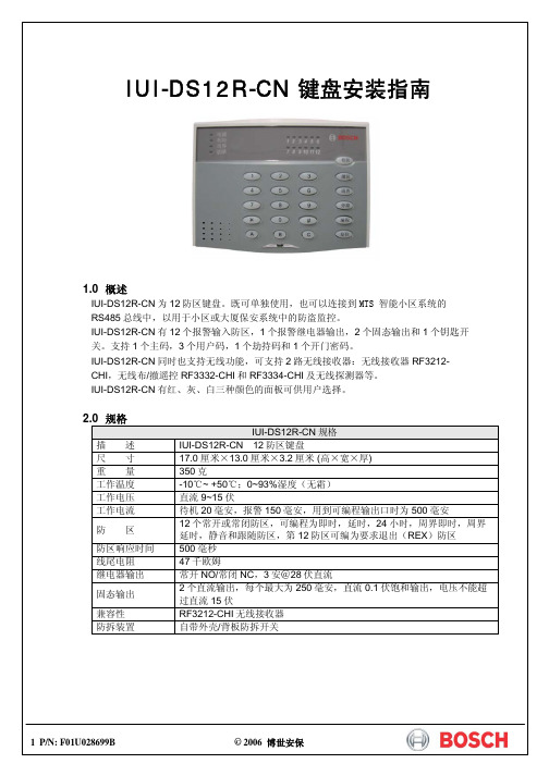
注意:不正确的操作可能会损坏外壳。
将底盖固定在适当的墙面或电气开关盒上;英寸电气开关盒安装时,请选择用螺钉在底板中‘墙面或其他尺寸电气盒安装时,请根据具体位置及尺寸选择用螺钉在底板中‘’处将其固定;如果需要使用防拆功能,IUI-DS12R-CN 必须是平面安装,将底盖上防拆开关位置上的塑料片去掉,在该位置上的墙面或盒面固定一个较长的坚硬物(如螺钉),用其顶住电路板上的防拆开关即可。
进线口AA接线端子排1接线端子排3IUI-DS12R-CN 主机PCB 板共有32个接线端子,分为(从右到左从1开始编号列表): 第一组 接线端子位置1第三组 接线端子位置1防拆开关第一组接线端子:接线端# 描述1 电源+(12伏直流)2 电源-(地)3 RS485 A接线端4 RS485 B接线端5 钥匙开关输入端6 固态继电器输出17 继电器公共端8 固态继电器输出2第二组接线端子:接线端# 描述1 防区12 公共端(地)3 防区24 防区35 公共端(地)6 防区47 防区58 公共端(地)9 防区610 防区711 公共端(地)12 防区8第三组接线端子:接线端# 描述1 防区92 公共端(地)3 防区104 防区115 公共端(地)6 防区127 即时防区8 警报输出常开端9 警报输出公共端10 警报输出常闭端11 无线设备数据线接口112 无线设备数据线接口24 P/N: F01U028699B © 2006 博世安保 IUI-DS12R-CN安装指南DS12R-CN:对于不同的地址应对应设置表中不同的值,若输入错误的值(数值长度不正确)。
可键取消刚输入的,然后重新输入。
返回到步骤4进行重新输入即可,但是若所输入的值不正确,数字长度正确,将发短3声进行提示,则必须重新输入编程地址及相应的值。
若想编程其它地址,则可重复步骤3和4。
10 P/N: F01U028699B © 2006 博世安保 IUI-DS12R-CN 安装指南5.1 编程数据查询在编程模式状态下,可以查询各个编程地址的当前值,其方法如下: 步骤 操 作 提 示1输入主码[x][x][x][x] 只有主码才具有编程模式,其它三个用户码不能用于编程。
星际科技 RK12WALHM 墙壁架机柜 12U说明书
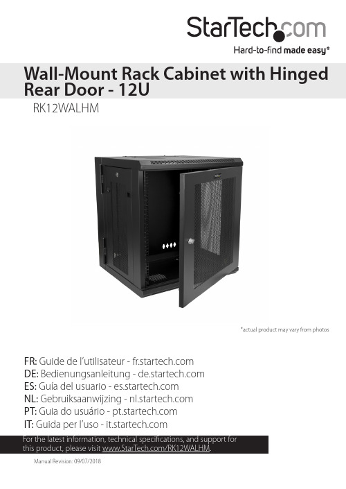
FR: Guide de l’utilisateur - DE: Bedienungsanleitung - ES: Guía del usuario - NL: Gebruiksaanwijzing - PT: Guia do usuário - IT: Guida per l’uso - RK12WALHMWall-Mount Rack Cabinet with Hinged Rear Door - 12U *actual product may vary from photosUse of Trademarks, Registered Trademarks, and other Protected Names and Symbols This manual may make reference to trademarks, registered trademarks, and otherprotected names and/or symbols of third-party companies not related in any way to . Where they occur these references are for illustrative purposes only and do not represent an endorsement of a product or service by , or an endorsement of the product(s) to which this manual applies by the third-party company in question. Regardless of any direct acknowledgement elsewhere in the body of this document, hereby acknowledges that all trademarks, registered trademarks, service marks, and other protected names and/or symbols contained in this manual and related documents are the property of their respective holders.PHILLIPS® is a registered trademark of Phillips Screw Company in the United States or other countries.Warning statements Varningsmeddelanden Waarschuwingen 注意Dichiarazioni di avvertenza AvertissementsMensagens de aviso Advertencias de uso WarnhinweiseTable of ContentsIntroduction (1)Product diagram (1)Product dimensions (2)Package contents (3)Requirements (3)Ground the enclosure (4)Lock or unlock the front or rear door (5)Remove the side panels (5)Access your cables (7)Reverse the front door (8)Adjust the depth of the mounting rails (10)Use the mounting rail tapped holes (11)Mount the enclosure to the wall (12)Install equipment (13)Technical support (14)Warranty information (14)Introduction Product diagram 13245457Front doorRear doorHorizontal mounting railVertical mounting railCable access coverCable access opening Side panel6Vent 37886Product dimensionsPackage contents• 1 x wall-mount enclosure• 1 x 1U shelf (CABSHELFV1U)• 1 x roll of hook-and-loop fastener• 48 x 12-24 cage nuts• 48 x 12-24 screws• 2 x door keys• 2 x side panel keys• 1 x instruction manualRequirements• Phillips type screwdriver• Appropriate tools and mounting hardware for the type of wall you’re using Requirements are subject to change. For the latest requirements, please visit /RK12WALHM.Ground the enclosureWarning! This product must be grounded. Do not use this product without an earth ground connection.1. Use an M6 screw to attach a grounding wire to the front or rear grounding point on the enclosure.2. Route the wire under the frame of the enclosure and connect the wire to your facility’s earth ground connection. (figure 1)figure 1Grounding wireLock or unlock the front or rear doorFor additional security, the front and rear door of the enclosure can be locked with the provided door keys.• To lock or unlock the front or rear door of the enclosure, insert one of the provided door keys in the lock on the door and turn the key clockwise or counterclockwise.Remove the side panels1. If the side panels are locked, use the provided side panel keys to unlock the panels.2. Pull the two tabs on the side panel towards the center of the panel. (figure 2)figure 2figure 33. Lift the side panel free from the enclosure. (figure 3)4.Repeat steps 1 to 3 to remove the other side panel.To put the side panels back on the enclosure, place one of the side panels in the groove at the bottom of the enclosure. Pull the two tabs on the side panel towards the center of the panel, push the top part of the side panel into the enclosure, and release the tabs. Use one of the provided side panel keys to lock the side panel.figure 4Access your cablesThere are two cable access covers on the enclosure that you can remove to access and manage your cables.1. To take off a cable access cover, use a Phillips type screwdriver to remove the two screws on both ends of the cable access cover.2. Pull the cable access cover away from the enclosure. (figure 4)To put the cable access cover back on, place the cover over the cable access opening and use a Phillips type screwdriver to insert the screws through the cover and into the enclosure. Tighten the screws.Reverse the front doorTo accommodate different rack configurations, you can reverse the front door of the enclosure so that it opens to the left or right of the enclosure. The front door of the enclosure is attached to the enclosure with levers that are located at the top and bottom of the front door.1. In the top corner of the inside of the front door, pull the lever down and move the top corner of the front door away from the enclosure.2. In the bottom corner of the inside of the front door, pull the lever up and remove the front door from the enclosure. (figure 5)figure 53. Flip the front door so that the levers are located on the opposite side.4. Position the front door so that the top and bottom levers are aligned with the washers located in the hinge area of the enclosure.5. In the top corner of the front door, pull the lever down and release it into the washer and hole in the enclosure.6. In the bottom corner of the front door, pull the lever up and release it into the washer and hole in the enclosure. (figure 6)figure 6Adjust the depth of the mounting rails The mounting rails come pre installed in the enclosure. The mounting rails can be adjusted independently in 3/4 inch (20 mm) increments to accommodate different sizes of equipment.Warning! Do not attempt to adjust the mounting rails when equipment is installed in the enclosure. Remove the equipment first before you adjust the mounting rails.1. Each of the mounting rails is connected to the enclosure with a screw and cage nut in the upper and lower corners of the mounting rail. Use a Phillips type screwdriver to remove the screws and cage nuts from the mounting rails.2. Install the cage nuts at the desired depth.3. Slide the mounting rail to the depth of the cage nuts and use a Phillips type screwdriver to install and tighten the screws that you removed in step 1. (figure 7)figure 7Use the mounting rail tapped holesThe mounting rails come preinstalled in the enclosure but you can adjust the mounting rails so that you can use the tapped holes to install your equipment.Warning! Do not attempt to adjust the mounting rails when equipment is installed in the enclosure. Remove the equipment first before you adjust the mounting rails.1. Each of the mounting rails is connected to the enclosure with a screw and cage nut in the upper and lower corners of the mounting rail. Use a Phillips type screwdriver to remove the screws and cage nuts from the mounting rails.2. Change the location of the mounting rails so that the sides of the rails with the tapped holes are facing the front door. (figure 8)3. To reattach the mounting rails to the enclosure, use a Phillips type screwdriver to install and tighten the screws that you removed in step 1.figure 8Mount the enclosure to the wallWarning! Remove all equipment from the enclosure before you attempt to mount the enclosure to the wall.Warning! Wall structures vary and it is important to make sure that the type ofwall structure and mounting hardware that you are using will properly support the mounted equipment. Failure to do so might result in personal injury and/or equipment damage. The wall structure should be capable of supporting at least four times the weight of the mounted equipment.The RK12WALHM weighs 59.5 lb. (27 kg) and can hold up to 198 lb. (90 kg) in weight.Warning! If you lack the necessary expertise to attach this product to the wall that you’re using, contact a construction professional to install the enclosure or to provide specific mounting instructions for your wall structure.The number of mounting holes on the rear door of the enclosure will vary depending on the model of your enclosure. Each mounting hole can accommodate an M8, M10, 5/16”, or 3/8” bolt.• Follow the appropriate steps for the type of wall that you’re attaching the enclosure to and attach the enclosure to the wall.Caution! The enclosure is extremely heavy and you should not attempt to lift and hang the enclosure without the assistance of other people.Install equipmentWarning! Do not add equipment to the enclosure until the enclosure is securely attached to the wall.Warning! When you load equipment into this enclosure, load the heaviest equipment in the bottom section of this enclosure first. Continue loading equipment in a descending order of weight, so that the lighter equipment is installed in the upper sections of this enclosure and the heavier items are on the bottom.This enclosure comes with cage nuts and screws but the equipment you’re installing may come with mounting hardware. Consult the documentation that came with the equipment to determine the best mounting hardware that you should use and how you should install it.1. Decide where in the enclosure you want to install the equipment and insert the cage nuts in the mounting rails.2. Line up the mounting holes on the equipment with the cage nuts.3. Insert the screws through the mounting holes on the equipment and into the cage nuts.Technical support’s lifetime technical support is an integral part of our commitment to provide industry-leading solutions. If you ever need help with your product, visit /support and access our comprehensive selection of online tools, documentation, and downloads.For the latest drivers/software, please visit /downloads Warranty informationThis product is backed by a five-year warranty. warrants its products against defects in materials and workmanship for the periods noted, following the initial date of purchase. During this period, the products may be returned for repair, or replacement with equivalent products at our discretion. The warranty covers parts and labor costs only. does not warrant its products from defects or damages arising from misuse, abuse, alteration, or normal wear and tear.Limitation of liabilityIn no event shall the liability of Ltd. and USA LLP (or their officers, directors, employees or agents) for any damages (whether direct or indirect, special, punitive, incidental, consequential, or otherwise), loss of profits, loss of business, or any pecuniary loss, arising out of or related to the use of the product exceed the actual price paid for the product. Some states do not allow the exclusion or limitation of incidental or consequential damages. If such laws apply, the limitations or exclusions contained in this statement may not apply to you.Hard-to-find made easy. At , that isn’t a slogan. It’s a promise. is your one-stop source for every connectivity part you need. From the latest technology to legacy products — and all the parts that bridge the old and new — we can help you find the parts that connect your solutions.We make it easy to locate the parts, and we quickly deliver them wherever they need to go. Just talk to one of our tech advisors or visit our website. You’ll be connected to the products you need in no time.Visit for complete information on all products and to access exclusive resources and time-saving tools. is an ISO 9001 Registered manufacturer of connectivity and technology parts. was founded in 1985 and has operations in the United States,。
lv12ab使用说明
lv12ab使用说明摘要:一、引言二、产品简介三、使用说明1.准备工作2.安装与激活3.功能介绍4.操作方法5.注意事项四、常见问题解答五、产品升级与售后服务正文:【引言】lv12ab 是一款广泛应用于各种场景的高性能产品。
为了帮助用户更好地了解和使用该产品,本文将详细介绍lv12ab 的使用说明。
【产品简介】lv12ab 是一款集成了先进技术与独特设计理念的产品,具有高效、稳定、易用等特点。
它旨在满足不同用户的需求,为用户带来优质的使用体验。
【使用说明】1.准备工作在使用lv12ab 前,请确保您的设备满足产品要求的硬件和软件配置,以便获得最佳性能。
同时,请确保设备已连接到电源,并确保电源稳定。
2.安装与激活请按照产品附带的安装指南进行安装。
安装完成后,请按照提示进行激活。
激活过程中,请确保您的设备已连接到网络,以便顺利完成激活。
3.功能介绍lv12ab 具有以下主要功能:(1)功能一(2)功能二(3)功能三4.操作方法(1)操作一:具体操作步骤(2)操作二:具体操作步骤(3)操作三:具体操作步骤5.注意事项在使用lv12ab 过程中,请务必注意以下事项:(1)请勿在潮湿、高温或灰尘环境中使用产品,以免影响设备性能和寿命。
(2)请勿擅自拆卸、改装或维修产品,以免造成安全事故。
(3)请定期检查设备运行状况,如有异常,请及时联系售后服务。
【常见问题解答】1.问题一:如何解决?2.问题二:如何解决?3.问题三:如何解决?【产品升级与售后服务】lv12ab 产品的升级和售后服务政策如下:1.产品升级:根据用户需求和产品实际情况,我们将不定期推出升级版本。
用户可以通过官方网站或指定渠道获取升级信息,并根据提示进行升级。
2.售后服务:我们提供一年的免费质保服务。
在质保期内,如产品出现非人为损坏的质量问题,我们将免费提供维修或更换。
NVIDIA Ada Tuning Guide Release 12.0说明书

Ada Tuning Guide, Release 12.0
8
Chapter 3. Application Compatibility
Chapter 4. NVIDIA Ada GPU Architecture Tuning
4.1. Streaming Multiprocessor
The NVIDIA Ada GPU architecture’s Streaming Multiprocessor (SM) provides the following improvements over Turing and NVIDIA Ampere GPU architectures.
3
Ada Tuning Guide, Release 12.0
4
Chapter 1. NVIDIA Ada GPU Architecture
Chapter 2. CUDA Best Practices
The performance guidelines and best practices described in the CUDA C++ Programming Guide and the CUDA C++ Best Practices Guide apply to all CUDA-capable GPU architectures. Programmers must primarily focus on following those recommendations to achieve the best performance. The high-priority recommendations from those guides are as follows:
MU12 全频扬声器产品说明书
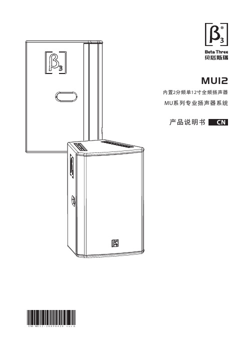
MU12音箱这个系统的设计采用的是免保护设计。大家 都知道有保护的扬声器音箱在使用过程中,特别是在保护电 路刚启动的时候,会有很多的电磁干扰对声音音质产生影响, 有些厂家的保护电路通过我们的检测发现,不仅没有保护作 用,还是一个干扰源。对于使用我公司跟随式保护电路可以 解决此类问题,但同样的会增加成本,因此MU12音箱在设 计当初我们就采用免保护设计的理念,尽量从减少干扰,提 高音质上考虑。
MU12音箱我们采用很多的新型材料,对于人们对于高 音比较敏感的听觉上考虑我们在高音驱动器上,经过多次试 验和测试实验,将高音驱动器的振膜改为了铝镁合金材料, 由于是合金材料,原理上讲,就具有比单一材料的阻尼要好, 3次谐波失真要小的特点,提高了高音单元的音质。
MU12音箱主要用于会议室、多功能厅、小型礼堂、宗教 会所、移动演出等场所。特别是对于人声的表现更是:“清晰, 饱满 ,且不失厚重”,这就是MU12音质特点。
毛重: 26kg(57.2 lb) 选配件: 飞机扣、音箱支架
扬声器的测量标准:
1.频率响应 噪声信号施加于扬声器,调整其电平,使扬声
器达到相当于标称阻抗下1W功率的电平,在消声 室环境中。距离扬声器1米处测试。
2.灵敏度 使用经过均衡曲线修正过的全频带粉红噪声信
号,施加于扬声器,将信号扩大,使扬声器达到相 当于标称阻抗下1W功率的电平,在消声室环境中、 距离扬声器1米处测得的平均声压级(dB-SPL)。
1. 请先阅读本说明。 2. 保留这些说明以供日后参照。 3. 注意所有警告信息。 4. 遵守各项操作指示。 5. 不要在雨水中或潮湿环境中使用本产品。 6. 不要将产品靠近热源安装,例如暖气管、加热器、 火炉或其它能产生热量的装置(包括功放机 )。 7. 不要破坏极性或接地插头的安全性设置。如果提供 的插头不能插入插座,则应当请专业人员更换插座。 8. 保护好电源线和信号线,不要在上面踩踏或拧在一起(尤 其是插头插座及穿出机体以外的部分 )。 9. 使用厂商规定及符合当地安全标准的附件。 10. 仅与厂商指定或与电器一同售出的推车 、架子 、三脚架、支架或桌子一起使用。推动小车/电器时,应谨防翻倒。 11. 雷电或长时间不使用时请断电以防止损坏产品。 12. 不要让物体或液体落入产品内——它们可能引起 火灾或触电。 13. 请注意产品外罩上的相关安全标志。
大全伊顿7.2-40.5KV维护检修培训资料 (1)

M10
28 Nm
M12
70 Nm
M12
40 Nm
M16
100 Nm
4.2接地开关:
每年需对接地开关进行常规维护,联锁是否可靠,传动齿 轮部分需加涂润滑脂,以保证其传动部分灵活,能连续分
合5次,视为合格。
接地开关传动齿 轮
4.3避雷器: 每年对避雷器进行测试,其试验参数与试验报告的参数
是否在误差范围内(10%),检查其接地是否可靠。
根据前下门接地开关操作说明进 行操作调整联锁拉板复位。
前下门
状态 断路器无法拉出
检查区域 手车室
可能原因
采取措施
断路器在工作 位置合闸。
断路器工作或 试验位置联锁未 解除。
分闸断路器,将断 路器驱进至试验位置。
18
110V
18
220V
75
220V
75
(1)**代表电流等级
(2)因产品改进,NVU12/3150A断路器各项参数与以前有所变化。
(3)因产品改进,部分型号分闸线圈电阻有所变化,部分型号分闸同期有所变化。
(4)分合闸线圈电阻为20℃时的电阻值,合闸线圈电阻允许偏差5%,分闸线圈电阻允许偏差10%。
四、一次电缆室维护检修
电缆室内一次主要安装电流互感器、接地开关及避雷器
4.1电流互感器
检查二次接线是否松动,对互感器一次连接部分检查(铜排固定螺栓 连接处检查,参照国家标准或企业生产标准)。具体参照值如下:
铜排与铜排连接 ;
铜排与互感器、绝缘子、传感器
M8
20 Nm
M8
14 Nm
M10
40 N m
NVU12/3150A(老)
15-55