TDS510usb2-e仿真器说明书
闻亭TDS510仿真机安装文档
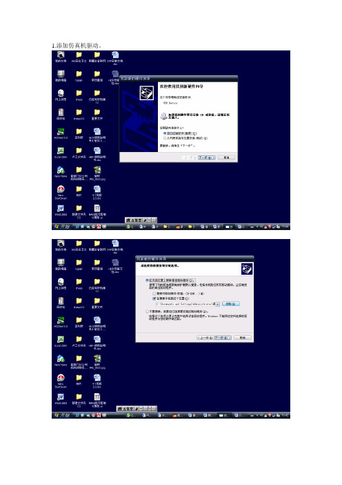
把这个remove掉
选择后点Browse…找到tds510usb文件夹(会找吧?向上就看见了!)点开他看见下面那个文件!点打开!
点next然后再next
点Add Single
再next
Frg2xx.bat
复制需写入的DSP程序文件到C:\tic2xx\cc\bin
桌面建prg2xx.bat快捷方式
编辑prg2xx.bat如下:
看清楚要加两行哦
运行prg2xx.bat
1.添加仿真机驱动。
2.安装::\闻亭仿真机\CC4.1 For C2000
3.安装:闻亭仿真机\tds510u2b
3.运行桌面图标Setup CC 'C2000
选上c2xx XD510 Emulator点Import然后点最下面的Close
先鼠标左键选中最左窗口里面的东西,再用鼠标右键选择中间窗口的东西出来快捷菜单中选最下面的那一项(不懂看图!)
TDS510USBPLUS仿真器用户使用说明书(CCS3.3)

5.1. USB 设备驱动程序安装...................................................................................... 2 5.2. 仿真支持软件安装 .............................................................................................. 2 5.3. CCS 仿真配置 ..................................................................................................... 2 附录 A................................................................................................................................... 9
3
TDS510USB PLUS 仿真器使用说明书
注意事项
请注意正确连接 14 针的 JTAG 电缆,该 电缆接错可能会导致仿真器或目标系 统永久损坏;仿真器 14 孔插头的第六 孔已经封闭,目标系统 JTAG 14 针插针
如果通过上述方法,不能找到您的目标板对应的仿真配置信息,
XDS510USB Emulator User Guide Chinese

X DS510DS510--USB2.0 DSP 仿真器使用说明书仿真器使用说明书敬告用户敬告用户首先感谢您使用XDS510-USB2.0 DSP 仿真器,使用前请认真阅读该说明书。
如果您已开始使用,说明您已阅读并接受本敬告。
1. 1. 本说明书中的资料如有更改本说明书中的资料如有更改本说明书中的资料如有更改,,恕不另行通知恕不另行通知。
2. 2. 在相关法律所允许的最大范围内在相关法律所允许的最大范围内在相关法律所允许的最大范围内,,本公司及其经销商对于因本产品故障所造成的任何损失均不承担责任障所造成的任何损失均不承担责任。
不论损害的方式如何不论损害的方式如何,,本公司及其经销商所赔付给您或其他责任人的责任总额经销商所赔付给您或其他责任人的责任总额,,以您对本产品的实际已付为最高额为最高额。
3. 3. 本公司及其经销商对所售产品自购买之日起本公司及其经销商对所售产品自购买之日起本公司及其经销商对所售产品自购买之日起一一年内免维修费用年内免维修费用((不包括更括更换元器件费用换元器件费用换元器件费用),),),其前提是您按说明书正常操作其前提是您按说明书正常操作其前提是您按说明书正常操作,,对于非正常操作所致的损坏所致的损坏,,实行收费修理实行收费修理。
保修凭证为仿真器封口标签保修凭证为仿真器封口标签,,用户必须保证其证其完整无损完整无损完整无损,,否则不予保修否则不予保修。
一、功能与特点功能与特点· 完全采用USB2.0 标准接口连接计算机,完全即插即用,传输速度可达480Mbps,是USB1.0 接口传输速度的40 倍以上。
兼容USB1.1 协议,兼容任何当前的USB1.1 接口 PC 机。
· 14PinJtag 仿真接口。
· 支持Windows98/ NT/2000/XP 操作系统。
· 支持TI CCS V2.0、V2.1、 V2.2 , 支持CCS3.1 、CCS3.2、CCS3.3集成开发环境,支持c 语言和汇编语言· 实现对F28x/F240x/F24x/F20x 的Flash 可编程。
TDS510 USB2.0仿真器说明书
目录目录 (1)TDS510 Ver3.3 DSP仿真器安装使用说明 (2)一.品质保证: (2)二.主要特点: (2)三。
套件组成: (4)五.驱动安装 (5)4.1 仿真器USB 设备驱动程序安装: (5)4. 安装仿真器CCS驱动和支持文件 (5)4.2运行Code Composer Studio Setup (7)4.3导入配置文件进行仿真器设置 (8)附录A:CCS5000 安装示例 (10)运行CCS SETUP (10)TDS510 Ver3.3 DSP 仿真器安装使用说明一.品质保证:敬告用户 欢迎您成为我公司DSP 仿真器产品的用户,在未阅读此敬告前请勿使用我公司产品。
如果您已开始使用,说明您已阅读并接受本敬告。
1. 本说明书中的资料如有更改,恕不另行通知。
2. 在相关法律所允许的最大范围内,本公司及其经销商对于因本产品 故障所造成的任何损失均不承担责任论损害的方式如何,本 公司及其经销商所赔付给您或其他责任人的责任总额,以您对本产品的实际已付为最高额。
3. 本公司及其经销商对所售产品自购买之日起三个月包换、一年保 修,其前提是您按说明书正常操作,对于非正常操作所致的损坏,实行收费修理。
二.主要特点:◆体积更小,1/2名片大小,目前国内体积最小仿真器◆采用最新一代CPLD 进行设计。
速度更快更加稳定。
隔离性能也更好。
不◆接口更加安全◆性能更加卓越◆速度较其他仿真器快一倍。
◆高强度ABS外壳设计。
体积更小重量更轻,避免了由于采用金属外壳,造成系统短路从而烧毁目标板事件的发生。
国内独创的变色LED指示灯对仿真器,目标板的工作状态进行初步诊断。
1.绿色:为USB指示灯。
插上USB线灯亮。
2.红色:为目标板电源灯,灯亮时表明仿真器和目标板均处于工作中。
3.黄色:绿黄两者交互指示灯。
两者有交互时,指示灯闪烁。
指示灯闪烁。
对两者的工作状态一目了然。
采用最新安全保护电路:采用全新目标板隔离电路,仿真器与目标板隔离度更好。
XDS510仿真器使用说明书

上海宇志通信技术有限公司
这样做是为了清空My System中的目标板,如果没有或者就是自己需要的目标板文件 就不需要进行这步清空操作了。出现如下图所示,在中间窗口的“Platform”下拉菜 单中选择xds510 emulator,双击下面的C671X XDS510 Emulator文件[如果是C5402 目标板请选择C5402 XDS510 Emulator,其他的目标板请选择对应的驱动文件],加载 到My System中去。
4.1 仿真器 USB 设备驱动程序安装: a.将仿真器通过随机的USB2.0通讯电缆连接到主机上的USB2.0接口上,为体现
上海宇志通信技术有限公司
USB2.0的速度优势,PC主机USB控制器必须是USB2.0接口。 b.仿真器与PC连接后,系统将提示找到新的USB设备,根据新设备安装向导,选
如果出现下图,请重新按照说明书检查驱动安装路径、CCS Setup等是否正确以及目 标板是否已经连接好。 直到能进入下图表示启动CCS正常了!
上海宇志通信技术有限公司
如果您在使用DSP仿真器过程中遇到任何问题欢迎咨询销售人员,我们会协助您 解决所遇到的问题。你也可以参考TI官方网站.
支持c 语言和汇编语言 · 实现对F28x/F240x/F24x/F20x 的Flash 可编程。 · 不占用目标系统资源,支持多个DSP 同时调试仿真。 · 宽工作电压范围:1V—5V,不需独立供电,使用PC 机电源。 · 支持热插拔,我公司的USB2.0 仿真器可在不关闭主机的情况下插拔而不会损坏。
上海宇志通信技术有限公司
右键点击上图左边的My System下面的C671X XDS510 Emulator选择Properties进行如 下图的设置。
ICETEK-5100USB2.0A仿真器CCSv4安装使用指南

3、CCSv4 驱动程序安装
双击 ICETEK-5100USB2.0A 目录下的“SetupICETEK5100USB20v4.exe ”程序,开始安装 CCSv4 驱动程序,过程如下: 1、如图:点击“Yes”,进入下一步
2、如图,点击“Next”,进入下一步
ICETEK-5100USB2.0A 仿真器 CCSv4 安装使用指南 1
瑞泰创新
9、如图,点击“finish”进入配置菜单
ICETEK-5100USB2.0A 仿真器 CCSv4 安装使用指南 6
瑞泰创新 10、如图,按照红色部分选择“ICETEK-5100USB2.0A Emulator”
11、如图,a,在红色部分�输入器件型号,例如,这里输入“tms320f2812”, b,在红色部分�打上“√” c,在红色部点击“Next”进入下一步
ICETEK-5100USB2.0A 仿真器 CCSv4 安装使用指南 4
瑞泰创新 6、如图,点击“Next”进入下一步
7、点击“Finish”完成工程创建
8、如图,执行 Target->New Target Configuration
ICETEK-5100USB2.0A 仿真器 CCSv4 安装使用指南 5
瑞泰创新
A 仿真器 CCSv 4 安装使 ICETEK-5100USB2.0 ICETEK-5100USB2.0A CCSv4 用指南
1、驱动程序的目录结构
驱动程序的目录结构如图:
ICETEK-5100USB2.0A 目录下包含 SetupICETEK5100USB20v4.exe 程序, 这个程序为 ICETEK-5100USB2.0A 仿真器的 CCSv4 驱动程序,将会在“CCSv4 驱动程序 安装”中使用 drivers 目录下是 windows XP 的 USB 接口驱动程序,将会在“硬件驱动安装 ”中使用 docs 目录包含本文件 <rootdir>表示 ICETEK-5100USB2.0A 目录的上级目录 以下的安装过程介绍将会以这个目录结构作为标准。
TDS510USBPLUS仿真器用户使用说明书(CCS3.3)
TDS510USB PLUS V3仿真器使用说明书(CCS3.3)闻亭数字系统(北京)有限公司敬告用户欢迎您成为闻亭公司的用户,在未阅读此敬告前请勿使用我公司产品。
如果您已开始使用,说明您已阅读并接受本敬告。
●本说明书中的资料如有更改,恕不另行通知。
●由于计算机类型及操作系统的多样型,闻亭公司及其经销商不保证所售产品适用于所有型号的计算机及操作系统。
●软件产品一经售出,不予以退货,若确因质量问题,可更换同类型软件。
●在相关法律所允许的最大范围内,闻亭公司及其经销商对于因本产品故障所造成的任何损失均不承担责任。
不论损害的方式如何,闻亭公司及其经销商所赔付给您或其他责任人的责任总额,以您对本产品的实际已付为最高额。
●本公司及其经销商对所售产品自购买之日起免费维修一年,其前提是您按说明书正常操作,若非正常操作所致的损坏,实行收费修理。
●本说明书的所有版权属于北京闻亭科技发展有限公司,未经本公司授权,不可对本文件的任何部分进行复印、复制或翻译成其他语言。
目录1.产品介绍 (1)2.系统需求 (1)3.产品特点 (1)4.特别说明 (2)5.安装使用向导 (2)B设备驱动程序安装 (2)5.2.仿真支持软件安装 (2)S仿真配置 (2)附录A (9)1.产品介绍TDS510USB PLUS V3仿真器适用于工作电压在1.0到5.0伏之间的TMS320系列数字信号处理器。
仿真器为USB接口设备,支持即插即用及热插拔。
支持windows2000/XP。
2.系统需求有USB接口的IBM PC兼容机或笔记本电脑,需要Pentium 233MHz以上,推荐使用PIII500以上配置来运行Code ComposerStudio((若要充分发挥USB的性能,主机必须具备USB2.0接口(用户自备))。
TDS510USB PLUS V3仿真器。
TDS510USB PLUS V3仿真器驱动程序盘(随仿真器提供)。
USB电缆(随仿真器提供)。
CCS3.3配TDS510仿真器安装与使用简易教程
CCS3.3配TDS510仿真器安装与使用简易教程一准备文件CCS3.3路径:\\192.168.1.5\刻盘\工具软件\DSP\CCS下的“CCS3.3”文件夹TDS510仿路径:\\192.168.1.5\刻盘\工具软件\DSP\仿真器驱动\DSP 仿真器 USB 2.0下的“驱动安装盘ccs3.3”二 CCS安装步骤1、将上述两文件夹复制到桌面2、打开“CCS3.3”文件夹下的“CCS3.3”文件夹,双击“setup.exe”3、点击“Next”4、不理会,继续点击“Next:5、选择接受,并点“Next“6、点击下图红框按钮以选择安装大部分主要功能(无特殊要求都够用)7、点击“Next“(这里以默认安装到C盘为例,如需安装其他盘符可自行更改)8、点击“Install Now“开始安装(过程较慢)9、弹出警告窗口,点确定10、点击“Finish”完成安装。
11、桌面出现两个图标(先不要动它们,继续安装驱动)三 TDS510驱动安装1、打开复制出来的文件夹“驱动安装盘ccs3.3”点击“SETUP.EXE”CCS支持中文,选择中文后点击“确定”2、点击“下一步”3、按下图标号顺序操作,必须预览到安装盘下CCS文件夹(默认C:\CCStudio_v3.1,这里要改为C:\CCStudio_v3.3)4、更改好后点击“下一步”4、在需要用到的芯片系列前打勾后点击“下一步”(不清楚就全选,文件不大)5、继续点击“下一步”后软件开始安装。
6、安装过程很快,点击“完成”,至此,仿真器安装尚未结束!!7、用方头USB线链仿真器口和接电脑USB口,将提示发现新硬件并弹出下图界面,选择如下,点“下一步”8、点击“预览”到拷贝出来的文件夹下的“USB_driver”,一次点击3、4处9、点击1处,预览到“桌面\驱动安装盘ccs3.3\USB_driver“下选择”usb510_sys“后点击3处确定10、点击完成。
MOXA UC-5100系列硬件用户手册说明书
UC-5100 Series Hardware User’s ManualEdition 1.2, September 2019/product© 2019 Moxa Inc. All rights reserved.UC-5100 Series Hardware User’s Manual The software described in this manual is furnished under a license agreement and may be used only in accordance withthe terms of that agreement.Copyright Notice© 2019 Moxa Inc. All rights reserved.TrademarksThe MOXA logo is a registered trademark of Moxa Inc.All other trademarks or registered marks in this manual belong to their respective manufacturers.DisclaimerInformation in this document is subject to change without notice and does not represent a commitment on the part of Moxa.Moxa provides this document as is, without warranty of any kind, either expressed or implied, including, but not limited to, its particular purpose. Moxa reserves the right to make improvements and/or changes to this manual, or to the products and/or the programs described in this manual, at any time.Information provided in this manual is intended to be accurate and reliable. However, Moxa assumes no responsibility for its use, or for any infringements on the rights of third parties that may result from its use.This product might include unintentional technical or typographical errors. Changes are periodically made to the information herein to correct such errors, and these changes are incorporated into new editions of the publication.Technical Support Contact Information/supportMoxa AmericasToll-free: 1-888-669-2872 Tel: +1-714-528-6777 Fax: +1-714-528-6778Moxa China (Shanghai office) Toll-free: 800-820-5036Tel: +86-21-5258-9955 Fax: +86-21-5258-5505Moxa EuropeTel: +49-89-3 70 03 99-0 Fax: +49-89-3 70 03 99-99Moxa Asia-PacificTel: +886-2-8919-1230 Fax: +886-2-8919-1231Moxa IndiaTel: +91-80-4172-9088 Fax: +91-80-4132-1045Table of Contents1.Introduction ...................................................................................................................................... 1-1Overview ........................................................................................................................................... 1-2 Model Descriptions .............................................................................................................................. 1-2 Package Checklist ............................................................................................................................... 1-2 Product Features ................................................................................................................................ 1-3 Hardware Block Diagram ..................................................................................................................... 1-3 2.Hardware Introduction...................................................................................................................... 2-1Appearance ........................................................................................................................................ 2-2 LED Indicators .................................................................................................................................... 2-5 Reset Button ...................................................................................................................................... 2-5 Reset to Default Button ....................................................................................................................... 2-5 Real Time Clock .................................................................................................................................. 2-5 Installation Options ............................................................................................................................. 2-6 DIN-Rail Mounting ....................................................................................................................... 2-6Optional DIN-Rail Mounting .......................................................................................................... 2-6 3.Hardware Connection Description ..................................................................................................... 3-1Wiring Requirements ........................................................................................................................... 3-2 Connecting the Power .................................................................................................................. 3-2Grounding the Unit ...................................................................................................................... 3-2 Connecting to the Console Port ............................................................................................................. 3-3 Connecting to the Network ................................................................................................................... 3-3 Connecting to a Serial Device ............................................................................................................... 3-4 Connecting to a DI/DO Device .............................................................................................................. 3-4 Connecting to a CAN Device ................................................................................................................. 3-4 Connecting to a USB Device ................................................................................................................. 3-5 Connecting the Cellular/Wi-Fi Module and Antenna ................................................................................. 3-5 Installing Micro SIM Cards ................................................................................................................... 3-7 Installing the SD Card ......................................................................................................................... 3-8 Adjusting the CAN DIP Switch .............................................................................................................. 3-8 Adjusting Serial Port DIP Switch ........................................................................................................... 3-8 A.Regulatory Approval Statements ....................................................................................................... A-11Introduction The UC-5100 Series embedded computers are designed for industrial automation applications. The computers feature 4 RS-232/422/485 full-signal serial ports with adjustable pull-up and pull-down resistors, dual CAN ports, dual LANs, 4 digital input channels, 4 digital output channels, a SD socket, and a mini PCIe socket for wireless module in a compact housing with convenient front-end access to all these communication interfaces. The following topics are covered in this chapter:❒Overview❒Model Descriptions❒Package Checklist❒Product Features❒Hardware Block DiagramOverviewThe UC-5100 Series embedded computers are designed for industrial automation applications. The computers feature 4 RS-232/422/485 full-signal serial ports with adjustable pull-up and pull-down resistors, dual CANports, dual LANs, 4 digital input channels, 4 digital output channels, a SD socket, and a mini PCIe socket for wireless module in a compact housing with convenient front-end access to all these communication interfaces. Model DescriptionsThe UC-5100 Series includes the following models:•UC-5101-LX: Industrial computing platform with 4 serial ports, 2 Ethernet ports, SD socket, 4 DI, 4 DO, -10 to 60°C operating temperature range•UC-5102-LX: Industrial computing platform with 4 serial ports, 2 Ethernet ports, SD socket, mini PCIe socket, 4 DI, 4 DO, -10 to 60°C operating temperature range•UC-5111-LX: Industrial computing platform with 4 serial ports, 2 Ethernet ports, SD socket, 2 CAN ports,4 DI, 4 DO,-10 to 60°C operating temperature range•UC-5112-LX: Industrial computing platform with 4 serial ports, 2 Ethernet ports, SD socket, mini PCIe socket, 2 CAN ports, 4 DI, 4 DO, -10 to 60°C operating temperature range•UC-5101-T-LX: Industrial computing platform with 4 serial ports, 2 Ethernet ports, SD socket, 4 DI, 4 DO, -40 to 85°C operating temperature range•UC-5102-T-LX: Industrial computing platform with 4 serial ports, 2 Ethernet ports, SD socket, mini PCIe socket, 4 DI, 4 DO, -40 to 85°C operating temperature range•UC-5111-T-LX: Industrial computing platform with 4 serial ports, 2 Ethernet ports, SD socket, 2 CAN ports,4 DI, 4 DO, -40 to 85°C operating temperature range•UC-5112-T-LX: Industrial computing platform with 4 serial ports, 2 Ethernet ports, SD socket, 2 CAN ports, mini PCIe socket, 4 DI, 4 DO, -40 to 85°C operating temperature rangeNOTE The operating temperature range of the wide temperature models is:-40 to 70°C with an LTE accessory installed-10 to 70°C with a Wi-Fi accessory installed.Package ChecklistBefore installing a UC-5100 computer, verify that the package contains the following items:•UC-5100 Series computer•Console cable•Power jack•Quick Installation Guide (printed)•Warranty cardNotify your sales representative if any of the above items are missing or damaged.NOTE The console cable and power jack can be found beneath the molded pulp cushioning inside the product box.Product Features•Armv7 Cortex-A8 1000 MHz processor•Dual auto-sensing 10/100 Mbps Ethernet ports• 4 software-selectable RS-232/422/485 ports supporting all signals•Dual Industrial CAN 2.0 A/B protocol supported•Moxa Industrial Linux with 10-year superior long term support•Mini PCIe socket for Wi-Fi/Cellular module•Micro SD socket for storage expansion•-40 to 85°wide temperature range and -40 to 70°C with LTE enabledFor a complete set of specifications, refer to the product datasheet available on the Moxa Website. Hardware Block Diagram2Hardware Introduction The UC-5100 embedded computers are compact and rugged, making them suitable for industrial applications. The LED indicators allow you to monitor performance and identify trouble spots quickly, and the multiple ports can be used to connect a variety of devices. The UC-5100 Series comes with a reliable and stable hardware platform that lets you devote the bulk of your time to application development. In this chapter, we provide basic information about the embedded computer’s hardware and its various components.The following topics are covered in this chapter:❒Appearance❒LED Indicators❒Reset Button❒Reset to Default Button❒Real Time Clock❒Installation OptionsD IN-Rail MountingO ptional DIN-Rail MountingAppearance Front ViewUC-5101UC-5102UC-5111UC-5112Dimensions [units: mm (in)] UC-5101UC-5102UC-5111UC-2112LED IndicatorsThe function of each LED is described in the table below: LED Name Status FunctionPower Green Power is on, and the device is functioning normally OffPower is offReadyYellow OS has been successfully enabled and the device is ready EthernetGreen Steady On: 10 Mbps Ethernet linkBlinking: Data transmission is in progress Yellow Steady On: 100 Mbps Ethernet linkBlinking: Data transmission is in progressOff Transmission speed below 10 Mbps or the cable is not connectedSerial (Tx) Green Serial port is transmitting data Off Serial port is not transmitting data Serial (Rx)Yellow Serial port is receiving data Off Serial port is not receiving dataL1/L2/L3(UC-5102/5112) YellowThe number of glowing LEDs indicates the signal strength. All LEDs: Excellent L1 & L2 LEDS : Good L1 LED : PoorOffNo wireless module detectedL1/L2/L3(UC-5101/5111)Yellow/OffProgrammable LEDs defined by usersReset ButtonThe UC-5100 computer is provided with a Reset button, which is located on the front panel of the computer. To reboot the computer, press the reset button for 1 second.Reset to Default ButtonThe UC-5100 is also provided with a Reset to Default button which can be used to reset the operating system back to the factory default status. Press and hold the Reset to Default button between 7 to 9 seconds to reset the computer to the factory default settings. When the reset button is held down, the Ready LED will blink once every second. The Ready LED will become steady when you hold the button continuously for 7 to 9 seconds. Release the button within this period to load the factory default settings.Real Time ClockThe UC-5100’s real time clock is powered by a non-chargeable battery. We strongly recommend that you do not replace the lithium battery without help from a qualified Moxa support engineer. If you need to change the battery, contact the Moxa RMA service team.Installation OptionsDIN-Rail MountingThe aluminum DIN-rail attachment plate is already attached to the product’s casing. To mount the UC-5100 on to a DIN rail, make sure that the stiff metal spring is facing upwards and follow these steps. Step 1Insert the top of the DIN rail into the slot just below the stiff metal spring in the upper hook of the DIN-rail mounting kit.Step 2Push the UC-5100 towards the DIN rail until theDIN-rail attachment bracket snaps into place.Optional DIN-Rail MountingThe UC-5100 can be mounted with the optional DIN rail mounting kit. Follow these steps for the installation. 1. Attach the optional DIN-rail mounting kit on therear panel with two screws.2. Pull down the slider of the DIN-rail bracketlocated at the back of the unit.3. Insert the top of the DIN rail into the slot justbelow the upper hook of the DIN-rail bracket. 4. Latch the unit firmly on to the DIN rail as shownin the illustrations below.5. Once the computer is mounted properly, youwill hear a click and the slider will rebound back into place automatically.Note this optional DIN-rail mounting kit should be purchased separately.3 Hardware Connection DescriptionIn this chapter, we describe how to connect the UC-5100 to a network and various devices for first time testing purposes.The following topics are covered in this chapter:❒Wiring RequirementsC onnecting the PowerG rounding the Unit❒Connecting to the Console Port❒Connecting to the Network❒Connecting to a Serial Device❒Connecting to a DI/DO Device❒Connecting to a CAN Device❒Connecting to a USB Device❒Connecting the Cellular/Wi-Fi Module and Antenna❒Installing Micro SIM Cards❒Installing the SD Card❒Adjusting the CAN DIP Switch❒Adjusting Serial Port DIP SwitchWiring RequirementsIn this section, we describe how to connect various devices to the embedded computer. Be sure to read and follow these common safety precautions before proceeding with the installation of any electronic device: • Use separate paths to route wiring for power and devices. If power wiring and device wiring paths mustcross, make sure the wires are perpendicular at the intersection point.NOTEDo not run signal or communication wiring and power wiring in the same wire conduit. To avoid interference, wires with different signal characteristics should be routed separately.• You can use the type of signal transmitted through a wire to determine which wires should be kept separate.The rule of thumb is that wiring that shares similar electrical characteristics can be bundled together. • Keep input wiring and output wiring separate.• When necessary, it is strongly advised that you label wiring to all devices in the system.Connecting the PowerTerminal BlockConnect the 9 to 48 VDC power line to the terminal block, which is connector to the UC-5100 Series computer. If the power is supplied properly, the “Power” LED will glow asolid green light. The power input location and pin definition are shown in the adjacent diagram.SG: The Shielded Ground (sometimes called Protected Ground) contact is at the bottomcontact of the 3-pin power terminal block connector when viewed from the angle shown here. Connect the wire to an appropriate grounded metal surface or through the groundingscrew on top of the device.Grounding the UnitGrounding and wire routing help limit the effects of noise due to electromagnetic interference (EMI). Run the ground connection from the ground screw to the grounding surface prior to connecting devices.Connecting to the Console PortThe UC-5100’s console port is a 4-pin pin-header RS-232 port located on the top panel of the case. It is designed for serial console terminals, which are useful for identifying the boot up message, or for debugging when the system cannot boot up.PIN Signal1 -2 - 3GND 4 TxD 5 RxD 6 - 7 - 8-Connecting to the NetworkThe Ethernet ports are located on the front panel of the UC-5100 computers. The pin assignments for the Ethernet port are shown in the following figure. If you are using your own cable, make sure that the pin assignments on the Ethernet cable connector match the pin assignments on the Ethernet port.PinSignal 1 Tx+ 2 Tx- 3 Rx+ 4 – 5– 6 Rx- 7 – 8–Connecting to a Serial DeviceThe serial ports are located on the front panel of the UC-5100 computer. Use a serial cable to connect your serial device to the computer’s serial port. These serial ports have RJ45 connectors and can be configured for RS-232, RS-422, or RS-485 communication. The pin location and assignments are shown in the table below.Pin RS-232RS-422 RS-485 1 DSR - - 2 RTS TxD+ - 3 GND GND GND 4 TxD TxD- - 5RxD RxD+ Data+ 6 DCD RxD-Data- 7 CTS - - 8DTR--Connecting to a DI/DO DeviceThe UC-5100 Series comes with 4 digital inputs and 4 digital outputs. The DI/DO connectors are located on the top panel of the computer. Refer to the diagram on the left for the pin definitions. For the wiring method, refer to the following figure:Connecting to a CAN DeviceThe UC-5111/5112 comes with 2 CAN ports, allowing users to connect CAN device. The pin location and assignments are shown in the following table:PIN Signal 1 CAN_H 2 CAN_L 3 CAN_GND4- 5 - 6 - 7 CAN_GND8-Connecting to a USB DeviceThe UC-5100 Series computers come with a USB port located at the lower part of the front panel, allowing users to connect to a device with an USB interface. The USB port uses a type A connector. Connecting the Cellular/Wi-Fi Module and AntennaThe UC-5102 and UC-5112 computerscome with one Mini PCIe socket forinstalling one cellular or Wi-Fi module.Unfasten the two screws on the rightpanel to remove the cover and find thelocation of the socket.The cellular module package includes 1 cellular module, and 2 screws. The cellular antennas should bepurchased separately to fit your installation requirements.Follow these steps to install the cellular module.1.Set the antenna cables aside for convenience of installation andclear the wireless module socket as shown in the figure.2.Insert the cellular module into the socket and fasten two screws(included in the package) on to the top of the module.We recommended using a tweezer when installing or removingthe module.3.Connect the free ends of the two antenna cables next to thescrews as shown in the image.4.Replace the cover and secure it using two screws.5.Connect the cellular antennas to the connectors.Antenna connectors are located on the front panel of thecomputer.The Wi-Fi module package includes 1 Wi-Fi module, and 2 screws. The antenna adapters and Wi-Fi antennas should be purchased separately to fit your installation requirements.Follow these steps to install a Wi-Fi module.1. Set the antenna cables aside and clear the wireless module socket as shown in the figure for convenience of installation.2. Insert the Wi-Fi module into the socket and fasten two screws (included in the package) on to the top of the module.We recommended using a tweezer when installing or removing the module.3. Connect the free ends of the two antenna cables next to the screws as shown in the image.4. Replace the cover and secure it with two screws.5. Connect the antenna adapters to the connectors on the front panel of the computer.6. Connect the Wi-Fi antennas to the antenna adapters.Installing Micro SIM CardsYou will need to install a Micro SIM card on your UC-5100 computer. Follow these steps to install the Micro SIM card.1. Remove the screw on the cover located on the frontpanel of the UC-5100.2. Insert the Micro SIM card into the socket. Make sureyou place the card in the right direction. To remove the Micro SIM card, simply push the Micro SIM card and release it. Note: There are two Micro SIM card sockets allowing users to install two Micro SIM cards simultaneously. However, only oneMicro SIM card can be enabled for use.UC-5100 Series Hardware Hardware Connection Description 3-8Installing the SD CardThe UC-5100 Series computers come with a socket for storage expansion that allows users to install an SD card. Follow these steps to install the SD card:1. Unfasten the screw and remove the panel cover.The SD socket is located on the front panel of thecomputer.2. Insert the SD card into the socket. Ensure that thecard is inserted in the right direction.3. Replace the cover and fasten the screw on thecover to secure the cover.To remove the SD card, simply push the card in andrelease it.Adjusting the CAN DIP SwitchThe UC-5111 and UC-5112 computers come with one CAN DIP switch for users to adjust the CAN termination resistor parameters. To set up the DIP switch, do the following:1. Find the DIP switch location on the top panel of thecomputer2. Adjust the setting as required. The ON value is 120Ω, and the default value is OFF.Adjusting Serial Port DIP SwitchThe UC-5100 computers come with a DIP switch for users to adjust the pull-up/pull-down resistors for the serial port parameters. The serial port DIP switch is located on the bottom panel of the computer.Adjust the setting as required. The ON setting corresponds to 1KΩ and the OFF setting corresponds to 150KΩ. The default setting is OFF.Each port consists of 4 pins; you must switch all 4 pins of a port simultaneously to adjust the value of the port.A Regulatory Approval StatementsThis device complies with part 15 of the FCC Rules. Operation is subject to the followingtwo conditions: (1) This device may not cause harmful interference, and (2) this devicemust accept any interference received, including interference that may cause undesiredoperation.Class A: FCC Warning! This equipment has been tested and found to comply with the limits for a Class A digital device, pursuant to part 15 of the FCC Rules. These limits are designed to provide reasonable protection against harmful interference when the equipment is operated in a commercial environment. This equipment generates, uses, and can radiate radio frequency energy and, if not installed and used in accordance with the instruction manual, may cause harmful interference to radio communications. Operation of this equipment in a residential area is likely to cause harmful interference in which case the users will be required to correct the interference at their own expense.European Community。
EUTEECH OAKLON CON 510 台式电导率 TDS 仪器 说明书
使用说明书CON 510台式电导率 / TDS 仪器Technology MadeEasy...68X090820 Rev. 0 11/02前言本手册说明了台式CON 510仪器的使用方法。
它有两种功能:首先是循序渐进的帮助用户学会如何去操作仪器,其次它可作为一本方便的使用指南。
本手册涵盖了仪器的多种应用,如果您在使用仪器中有任何疑问,请立即与离您最近的Eutech授权经销商联系。
Eutech/Oakton仪器公司将不承担由于使用不当引起损坏和故障的任何责任。
本手册的内容将随着科技进步而改变,此种情况Eutech/Oakton仪器公司将不专门通知客户并不承担由此引起的任何责任。
注意:Eutech/Oakton仪器有限公司在改进仪器的设计,配置和外观方面,具有最终解释权。
© 2002 Eutech/Oakton仪器有限公司版权所有版本 0 11/02目录1序言 (1)2显示和键盘功能 (1)2.1显示 (1)2.2键盘 (2)3准备工作 (3)3.1电导率电极相关信息 (3)3.2连接电极 (3)3.3连接AC/DC适配器 (3)3.4连接电极固定物 (4)4校正 (5)4.1仪器校正的重要信息 (5)4.2仪器校正的准备工作 (6)4.3电导率标准液和TDS因子的校正 (6)4.4直接校正TDS标准 (6)4.5选择自动和手动校正 (6)4.6自动校正(只适合电导率模式) (7)4.7手动校正(电导率/TDS) (8)4.8温度校正 (9)5测量 (10)5.1自动温度补偿 (10)5.2手动温度补偿 (11)5.3进行测量 (11)5.4使用手动量程切换功能 (12)5.5锁定功能 (12)6记忆和数据输入功能 (13)6.1记忆输入 (13)6.2调用记忆 (13)7设置功能 (14)7.1设置模式 (14)7.2P1.0: 查看校正数据 (15)7.3P2.0: 查看电极诊断 (16)7.4P3.0: 仪器的配置 (16)7.5P4.0: 温度 (18)7.6P5.0校正模式 (20)7.7P6.0 选择电池常数 (21)7.8P7.0: 恢复出厂设置 (22)8电极的维护和保养 (23)9故障维修指南 (24)10错误信息 (24)11规格 (25)12配件 (26)13注意:电导率和TDS标准液,在25°C时具有±1%的精度,请参见附件1: 校正要点 (27)14附录2: 计算tds转化因子 (27)15附录3: 计算温度系数 (28)16附录4: 仪器出厂设置 (29)17质量保证 (30)18返还条款 (30)1 简介感谢您选购了台式CON510仪器。
- 1、下载文档前请自行甄别文档内容的完整性,平台不提供额外的编辑、内容补充、找答案等附加服务。
- 2、"仅部分预览"的文档,不可在线预览部分如存在完整性等问题,可反馈申请退款(可完整预览的文档不适用该条件!)。
- 3、如文档侵犯您的权益,请联系客服反馈,我们会尽快为您处理(人工客服工作时间:9:00-18:30)。
TDS510USB2-E仿真器使用说明书
一、产品介绍
TDS510USB2-E仿真器适用于工作电压在1.0到5.0伏之间的数字信号处理器。
仿真器为USB2.0接口设备,支持即插即用及热插拔。
支持windows98/2000/XP。
二、 系统需求
1. 有USB接口IBM PC兼容机或笔记本电脑,需要有足够的资源运行Code
Composer Studio。
要充分发挥USB2.0的性能,你的主机必须具备USB2.0
接口。
(用户自备)
2. TDS510USB2-E仿真器。
3. TDS510USB2-E仿真器驱动程序盘。
(随仿真器提供)
4. USB电缆。
(随仿真器提供)
5. 带有TI DSP以及JTAG仿真端口的目标系统。
(用户自备)
6. Code Composer 4.1x或Code Composer Studio 1.2以上版本。
(需单独购
买)
三、 产品特点
1. 支持TI的C28X、VC33、C5000、C6000系列芯片。
2. 支持1.0~5.0伏目标DSP电压。
3. 采用USB2.0接口,传输速度可达到480Mb/s,完全即插即用,无跳线。
4. 兼容USB1.1接口,可直接插在USB1.1接口上使用,在USB1.1接口上
传输速度为12Mb/s。
5. 支持热插拔,TDS510USB2-E仿真器可以在不关闭主机的情况下插拔而不
会损坏。
6. 通过USB接口供电,无需外接电源。
7. 支持Texas Instrument的Code Composer Studio(CCS)。
四、 安装向导
1. USB设备驱动程序安装。
1. 不连接目标板,将仿真器通过USB电缆连接到主机上的USB接口。
2. 系统将提示找到新USB设备,根据系统安装新设备向导,选择自动
搜索设备驱动程序,并将搜索路径指定为TDS510USB2-E仿真器驱
动程序所在路径(CDROM 根目录),按“下一步”按钮,根据提示完
成驱动程序安装。
3. 设备驱动程序安装完成后在系统设备列表里应该可以看到在
WintechDigital里增加了WintechDigital TDS510 USB2.0 JTAG
Emulator设备。
4. 安装CCS驱动。
2. CCS驱动程序的安装。
参见附录A
以上步骤完成后,现在连接目标板,并打开目标电源,运行CCS,你就可以用TDS510USB2-E仿真器来调试你的目标系统。
关于CCS驱动程序安装的更多信息,请参阅CCS用户手册。
附录A:
Code Composer Studio Setup
1.Double click on setup.exe on your CDROM to install the TDS510USB2-E
JTAG emulator tools for CCS.
2. Click on “Start” button —〉Program —〉Texas Instrument —〉Code
Composer Studio 6000 —〉Setup CCS 2(6000),Code Composer Studio
Setup window will appear.
3. Double click on C6000 XDS(Texas Instrument)on the middle column (see
Figure 1), the “Board Properties” window will pop-up.(If the “Import
Configuration” window appears instead (see Figure 2), just click on
“Close”.)
Note:
l Double click on C54X XDS(Texas Instrument)or C55X XDS(Texas Instrument)if your target CPU is C5000.
l If your target CPU is VC3X, you need to click on Install a Device Driver on the right column to install tds510vc3x.dvr.
Figure 1
Figure 2
4. On the “Board Properties” Window, click on “Auto-generate board data file” and
change it to “Auto-generate board file with extra configuration file”(see Figure 3). Then Click on “Browse” to find the CCS folder (the default path is
C:\ti\cc\bin),choose WINTECH.CFG and click on “Open”.
Figure 3
5. Click on “Next”, you will see the I/O Port Value: 0x0 (see Figure 4) .
Figure 4
6. Click on “Next” to get to the Process Configuration page (see Figure 5).
According to the type of the target board and the number of each type of the target boards you have, choose the appropriate processor and click on “Add Single”or “Add Multiple”(see Figure 5).
Figure 5
7. Click on “Next” will bring you to the “Startup GEL File(s) page (Figure 6).
Click on the “”button to see a list of gel files. Choose the gel file that
matches your target board. Click on “Finish”. (For some target board, if you
don’t choose a gel file, it may cause error while loading program to CCS. )
Figure 6
8. To save the configuration and exit the “Code Composer Studio Setup”window,
click on “File”and then “Exit”.。