Maxim MAX16826高亮LED(HBLED)驱动方案
MaximMAX16834大功率LED驱动方案(1

Maxim MAX16834大功率LED驱动方案(1)-Maxim 公司的MAX16834是集成了高边LED电流检测和PWM调光MOSFET驱动器的大功率LED驱动器。
这种恒流模式高亮度LED(HBLED)驱动器适合于升压,升-降压,SEPIC 和高边降压拓扑。
工作电压从.4.75V到28V,PWM调光/模拟调光比3000:1,可编程工作频率100kHz到1MHz,主要应用在单串LED LCD背光,汽车前后灯照明,投映RGB LED光源,环境照明和DC-DC升压/降压-升压转换器。
本文介绍了MAX16834主要特性,方框图以及多种应用电路。
High-Power LED Driver with Integrated High-Side LED Current Sense and PWM Dimming MOSFET DriverThe MAX16834 is a current-mode high-brightness LED (HB LED) driver for boost, boost-buck, SEPIC, and highside buck topologies. In addition to driving an n-channEL power MOSFET switch controlled by the switching controller, it also drives an n-channel PWM dimming switch to achieve LED PWM dimming. The MAX16834 integrates all the building blocks necessary to implement a fixed-frequency HB LED driver with wide-range dimming control.The MAX16834 features constant-frequency peak current-mode control with programmable slope compensation to control the duty cycle of the PWM controller.A dimming driver designed to drive an external n-channel MOSFET in series with the LED string provides wide-range dimming control up to 20kHz. In addition to PWM dimming, theMAX16834 provides analog dimming using a DC input at REFI. The programmable switching frequency (100kHz to 1MHz) allows design optimization for efficiency and board space reduction.A single resistor from RT/SYNC to ground sets the switching frequency from 100kHz to 1MHz while an external clock signal at RT/SYNC disables the internal oscillator and allows the MAX16834 to synchronize to an external clock. The MAX16834’s integrated highside current-sense amplifier eliminates the need for a separate high-side LED current-sense amplifier in boost-buck applications.The MAX16834 operates over a wide supply range of 4.75V to 28V and includes a 3A sink/source gate driver for driving a power MOSFET in high-power LED driver applications. It can。
MAX25600 高压电压高明亮 LED(HB LED)槽桩控制器评估套件说明书

MAX25600EVKIT#Evaluates: MAX25600 MAX25600 Evaluation KitGeneral DescriptionThe MAX25600 evaluation kit (EV kit) provides a proven design to evaluate the MAX25600 automotive high-volt-age, high-brightness LED (HB LED) buck boost controller. The EV kit operates from 8V to 48V DC supply voltage. The EV kit is configured to deliver up to 1.5A to one string of one to fifteen LEDs. The total voltage of the string can vary from 3V to 60V. The anode of the LED string should go to LED+ terminal and the cathode to the LED- terminal. Benefits and Features●8V to 48V Input Voltage Range●Demonstrates Analog Dimming Control, DigitalDimming Control●Demonstrates Input Current Limit●Demonstrates LED Current Monitoring function●Demonstrates LED Short and Open Protection●Proven PCB Layout●Fully Assembled and TestedOrdering Information appears at end of data sheet.Quick StartRequired Equipment●MAX25600 EV kit●12V, 5A DC power supply● A series-connected LED string rated at least 1.5A●Oscilloscope with a current probeProcedureThe EV kit is fully assembled and tested. Follow the steps below to verify board operation:Caution: Do not turn on the power supply until all connections are made.1) Verify that all jumpers are in their default positions,as shown in Table 1.2) Connect the positive terminal of the 12V supply tothe VINP1 board PCB pad and the negative terminal to the GND1_board PCB pad.3) Connect the LED string across the LED+ and LED-PCB pads on the EV kit. The Anode of the LEDstring should go to the LED+ PCB pad and Cathode of the LED string to LED- PCB pad.4) Clip the current probe on the wire connected to theLED string.5) Turn on the DC power supply.6) Verify that the LEDs turn on.7) Verify that the oscilloscope displays approximately1.5A.Click here for production status of specific part numbers.PRELIMINARYEvaluates: MAX25600MAX25600 Evaluation Kit Detailed DescriptionThe MAX25600 evaluation kit (EV kit) provides a proven design to evaluate the MAX25600 automotive high-volt-age, high-brightness LED (HB LED) buck boost controller. The EV kit operates from 8V to 48V DC supply voltage. The EV kit is configured to deliver up to 1.5A to one string of LEDs. The total voltage of the string can vary from 3V to 60V. The anode of the LED string should go to LED+ terminal and the cathode to the LED- terminal.Analog Dimming Control (ICTRL)When J2 is closed, the LED current is set by resistive divider from VCC. The equation to set the LED current isICTRLLED V 200mVI 5R9−=×In the case of the EV kit, ILED is set to 1.5A. Use a screw driver on the potentiometer R21 to adjust the LED current.PWM DimmingThe EV kit demonstrates the PWM dimming feature of the MAX25600 using either an external PWM signal, or a DC voltage at the PWMDIM pin.External PWM dimming:Keep J4 open and remove the 0.1uF C55 capacitor (installed by default). Connect an external PWM signal to the PWMDIM test point. Vary the duty cycle to increase or decrease the intensity of the HB LED string. The PWMDIM input of the device has a 2V (max) rising thresh-old and a 0.4V (min) falling threshold and is compatible with 3.3V and 5V logic-level signals.Analog-to-PWM dimming:Keep J4 open and keep the 0.1uF C55 (installed by default). The PWM dimming duty cycle is set by the volt-age at PWMDIM between 0.2V (0% duty) and 3.2V (100% duty). Drive the PWMDIM test point with an external DC source. PWMDIM voltages above 3.2V set the dimming duty cycle to 100%.Table 1. MAX25600 EV Kit Jumper DescriptionsJUMPE R SHUNT POSITIONDESCRIPTIONJ1Closed Short the PMOS PWM dimming switch.Open*PWM Dimming done with the PMOS switchJ2Closed Uses the resistive divider from VCC and the potentiometer R21 to set the LED current.Open Apply an external dc voltage between 0.2V to 1.2V for setting LED current.J3OpenConnect an external power supply for the IN pin of the IC using the IN_IC PAD.1-2*Connects the IN input of the IC to the VIN power supply connected on VINP1 PAD.2-3The IN and VCC inputs of the IC are shorted and should be driven with an external 5V supply.J4OpenApply an external PWM clock source for PWM dimming or apply an external dc source between 0.2V to 3.2V for analog PWM dimming.1-2*PWMDIM pin pulled to VCC for 100% duty.2-3PWMDIM pin pulled to GND to turn OFF.PRELIMINARYEvaluates: MAX25600MAX25600 Evaluation Kit Current Monitor OutputThe EV kit also demonstrates the current-monitor out-put feature of the buck boost controller. The MAX25600 includes a current monitor on the IOUTV pin. The IOUTV voltage is an analog voltage indication of the LED current when DIM is high. The voltage on the IOUTV pin is given by the following equation:V IOUTV = I LED x R CS_LED x 5 + 0.2VInput-Current LimitThe MAX25600 features circuitry that limits the input cur-rent during line dropouts. Refer to the IC datasheet for details on setting the input current limit.External VCC inputThe EV kit demonstrates operation of the buck boost con-troller with an external VCC input. In this case, the internal LDO is not used. Move the shunt to pins 2-3 on J3 (the IN and VCC pins of the buck controller are shorted together). Apply an external power supply between 4.6V and 5.5V on the IN_IC PCB pad to allow switching of the device.FaultsOpen and Short LEDs:The IC detects the open and short fault conditions of the LEDs and the fault pin is pulled low. The fault pin also goes low when there is an overtemperature condition. The fault pin is an open-drain output and is active low.#Denotes RoHS compliant.PART TYPE MAX25600EVKIT#EV KitOrdering InformationPRELIMINARYEvaluates: MAX25600 MAX25600 Evaluation KitMAX25600 EV Kit Bill of MaterialsITEM QTY REF DES MFG PART #MANUFACTURER VALUE DESCRIPTION19AGND, ICTRL, IN_IC, LED+,LED-, PGND, PGND1,PWMDIM, VINP19020 BUSS WEICO WIRE MAXIMPAD EVK KIT PARTS; MAXIM PAD; WIRE; NATURAL;SOLID; WEICO WIRE; SOFT DRAWN BUS TYPE-S; 20AWG26C1, C4, C20, C22,C24, C55885012206071;CGJ3E2X7R1E104K080AA;C1608X7R1E104K080AA;C0603C104K3RAC;GRM188R71E104KA01;C1608X7R1E104KWURTH ELECTRONICS INC;TDK;TDK;KEMET0.1UFCAPACITOR; SMT; 0603; CERAMIC; 0.1uF; 25V;10%; X7R; -55degC to + 125degC; +/-15% from -55degC to+125degC39C2, C3, C6, C7, C9,C10, C12, C13, C15CGA6M3X7S2A475K200AE;CGA6M3X7S2A475K200ABTDK;TDK 4.7UF CAPACITOR; SMT (1210); CERAMIC CHIP; 4.7UF;100V; TOL=10%; TG=-55 DEGC TO +125 DEGC; TC=X7S; AUTO41C5CGA3E3X7S2A104K080AB TDK0.1UF CAPACITOR; SMT (0603); CERAMIC CHIP; 0.1UF;100V; TOL=10%; TG=-55 DEGC TO +125 DEGC; TC=X7S53C8, C14, C21CC0603KRX7R0BB104;GRM188R72A104KA35;GCJ188R72A104KA01;HMK107B7104KA;06031C104KAT2AYAGEO;MURATA;MURATA;TAIYO YUDEN;AVX0.1UF CAPACITOR; SMT (0603); CERAMIC CHIP; 0.1UF;100V; TOL=10%; TG=-55 DEGC TO +125 DEGC; TC=X7R61C11EEV-FK2A680Q PANASONIC68UF CAPACITOR; SMT (CASE_H13); ALUMINUM-ELECTROLYTIC; 68UF; 100V; TOL=20%; MODEL=EEV SERIES71C17C0603C471K1RAC; 06031C471KAT2A KEMET;AVX470PF CAPACITOR; SMT; 0603; CERAMIC; 470pF; 100V;10%; X7R; -55degC to + 125degC; +/-15% from -55degC to +125degC81C18C0603X5R160-105KNP;EMK107BJ105KA;C1608X5R1C105K080AA;GRM188R61C105K;0603YD105KAT2A;CL10A105KO8NNNVENKEL LTD.;TAIYO YUDEN;TDK;MURATA;AVX;SAMSUNGELECTRO-MECHANICS1UFCAPACITOR; SMT; 0603; CERAMIC; 1uF; 16V;10%; X5R; -55degC to + 85degC; 0 +/-15% degC E 20-0001u-63 FOR NEW DESIGN91C19C1608C0G1E103J080AA TDK0.01UF CAPACITOR; SMT (0603); CERAMIC CHIP;0.01UF; 25V; TOL=5%; MODEL=; TG=-55 DEGC TO +125 DEGC; TC=C0G101C23C1608X5R1E225K;TMK107ABJ225KA;TMK107BJ225KA;GRM188R61E225KA12TDK;TAIYO YUDEN;TAIYO YUDEN;MURATA2.2UF CAPACITOR; SMT (0603); CERAMIC CHIP; 2.2UF;25V; TOL=10%; MODEL=; TG=-55 DEGC TO +85 DEGC; TC=X5R111C25C0603H102J1GAC KEMET1000PF CAPACITOR; SMT (0603); CERAMIC CHIP; 1000PF;100V; TOL=5%; MODEL=HT SERIES; TG=-55 DEGC TO +200 DEGC; TC=C0G121C51CGA3E2X8R1E104K080AE TDK0.1UF CAP; SMT (0603); 0.1UF; 10%; 25V; X8R;CERAMIC CHIP134D1, D2, D5, D61N4148W-7-F DIODES INCORPORATED1N4148W-7-F DIODE; SWT; SMT (SOD-123); PIV=100V; IF=0.3A;-65 DEGC TO +150 DEGC142D7, D8BAT46WJ NXP BAT46WJ,115DIODE; SCH; SMT (SOD-323F); PIV=100V; IF=0.25A151FB1HF70ACB322513TDK52INDUCTOR; SMT (1210); FERRITE-BEAD; 52;TOL=+/-25%; 0.4A; -40 DEGC TO +125 DEGC163FLTB, IOUTV, VCC5007KEYSTONE N/A TEST POINT; PIN DIA=0.125IN; TOTAL LENGTH=0.35IN; BOARD HOLE=0.063IN; WHITE; PHOSPHOR BRONZE WIRE SILVER PLATE FINISH;172J1, J2PCC02SAAN SULLINS PCC02SAAN CONNECTOR; MALE; THROUGH HOLE;BREAKAWAY; STRAIGHT THROUGH; 2PINS; -65 DEGC TO +125 DEGC182J3, J4PCC03SAAN SULLINS PCC03SAAN CONNECTOR; MALE; THROUGH HOLE;BREAKAWAY; STRAIGHT THROUGH; 3PINS; -65 DEGC TO +125 DEGC191L1MSS1278-103ML COILCRAFT10UH INDUCTOR; SMT; FERRITE CORE; 10UH; TOL=+/-20%; 5.7A 201L2MSS1278T-472ML COILCRAFT 4.7UH INDUCTOR; SMT; FERRITE BOBBIN CORE;4.7UH; TOL=+/-0.2; 6.2A; -40 DEGC TO +125 DEGC212Q1, Q3SQJA84EP-T1_GE3VISHAY SILICONIX SQJA84EP-T1_GE3TRAN; AUTOMOTIVE N-CHANNEL MOSFET ;NCH; SO-8L; PD-(55W); I-(46A); V-(80V)221Q2BUK9Y72-80E NEXPERIA BUK9Y72-80E TRAN; N-CH LOGIC LEVEL MOSFET ; NCH;LFPAK; PD-(45W); I-(15A); V-(80V)231Q4BUK9Y25-80E NEXPERIA BUK9Y25-80E TRAN; N-CH LOGIC LEVEL MOSFET ; NCH;LFPAK; PD-(95W); I-(37A); V-(80V)241Q5SI7415DN-T1-GE3VISHAY SILICONIX SI7415DN-T1-GE3TRAN; P-CHANNEL 60-V (D-S) MOSFET; PCH;POWERPAK1212-8; PD-(3.8W); I-(-5.7A); V-(-60V)2510R1, R3, R4, R6-R8,R13, R25, R27, R28CRCW06030000Z0VISHAY DALE0RESISTOR; 0603; 0 OHM; 0%; JUMPER; 0.1W; THICK FILM 262R2, R12CRCW06035R62FK VISHAY DALE 5.62RESISTOR; 0603; 5.62 OHM; 1%; 100PPM; 0.10W; THICK FILM 275R5, R11, R17, R19, R20301-10K-RC XICON10K RESISTOR, 0603, 10K OHM, 5%, 200PPM, 1/16W, THICK FILM 281R9CSR1206FTR130STACKPOLE ELECTRONICS INC0.13RESISTOR; 1206; 0.13 OHM; 1%; 100PPM; 0.5W; THICK FILM 291R10ERJ-3EKF5113PANASONIC511K RESISTOR; 0603; 511K OHM; 1%; 100PPM; 0.1W; THICK FILM 301R16CRCW060354K9FK VISHAY DALE54.9K RES; SMT (0603); 54.9K; 1%; +/-100PPM/DEGC; 0.1W311R18288-0603-49.9K-RC XICON49.9K RESISTOR, 0603, 49.9K OHM, 0.1%, 10PPM, 1/16W, THIN FILM321R213296W-1-103LF BOURNS10K RESISTOR; THROUGH-HOLE-RADIAL LEAD;3296 SERIES; 10K OHM; 10%; 100PPM; 0.5W; SQUARE TRIMMING POTENTIOMETER; 25 TURNS; MOLDER CERAMIC OVER METAL FILM331R22CRCW0603560RFK VISHAY DALE560RESISTOR, 0603, 560 OHM, 1%, 100PPM, 0.10W, THICK FILM341R23RG1608P-101-B;ERA-3YEB101V SUSUMU CO LTD.;PANASONIC100RESISTOR; 0603; 100 OHM; 0.1%; 25PPM; 0.1W; THICK FILM351R24RCS060312R0FK VISHAY DALE12RESISTOR; 0603; 12 OHM; 1%; 100PPM; 0.25W; THICK FILM361R26CRCW060349R9FK VISHAY DALE49.9RESISTOR; 0603; 49.9 OHM; 1%; 100PPM; 0.10W; THICK FILM371R55CRCW08051R00FK VISHAY DALE1RESISTOR; 0805; 1 OHM; 1%; 100PPM; 0.125W; THICK FILM382RN1, RN2ERJ-8BWFR024PANASONIC0.024RES; SMT (1206); 0.024; 1%; +/-150PPM/DEGC; 1W392RS1, RS2TLM2BER012F TE CONNECTIVITY0.012RES; SMT (1206); 0.012; 1%; +/-100PPM/DEGC;0.5W;NOTE:PURCHASE DIRECT FROM THE MANUFACTURER401TP17007KEYSTONE7007CONNECTOR; PANELMOUNT; BINDING POST;STRAIGHT THROUGH; 1PIN; BLACK411TP107006KEYSTONE7006CONNECTOR; PANELMOUNT; BINDING POST;STRAIGHT THROUGH; 1PIN; RED421U1MAX25600MAXIM MAX25600EVKIT PART-IC; MAX25600; QFN28-EP; PACKAGE OUTLINEDRAWING: 21-100130; PACKAGE CODE: T2855+5C431PCB MAX25600MAXIM PCB PCB:MAX25600PRELIMINARYEvaluates: MAX25600 MAX25600 Evaluation KitPRELIMINARYEvaluates: MAX25600MAX25600 Evaluation Kit MAX25600 EV Kit Component Placement Guide—Top SilkscreenMAX25600 EV Kit PCB Layout—Top ViewPRELIMINARYEvaluates: MAX25600MAX25600 Evaluation Kit MAX25600 EV Kit PCB Layout—Internal2MAX25600 EV Kit PCB Layout—Internal3PRELIMINARYEvaluates: MAX25600MAX25600 Evaluation Kit MAX25600 EV Kit PCB Layout—Bottom ViewMAX25600 EV Kit Component Placement Guide—Bottom SilkscreenPRELIMINARYEvaluates: MAX25600 MAX25600 Evaluation KitREVISION NUMBER REVISIONDATEDESCRIPTIONPAGESCHANGED05/19Initial release—Revision HistoryFor pricing, delivery, and ordering information, please visit Maxim Integrated’s online storefront at https:///en/storefront/storefront.html.PRELIMINARYMAX25600EVKIT#。
基于美信MAX16836多颗高亮LED驱动设计方案
基于美信MAX16836多颗高亮LED驱动设计方案
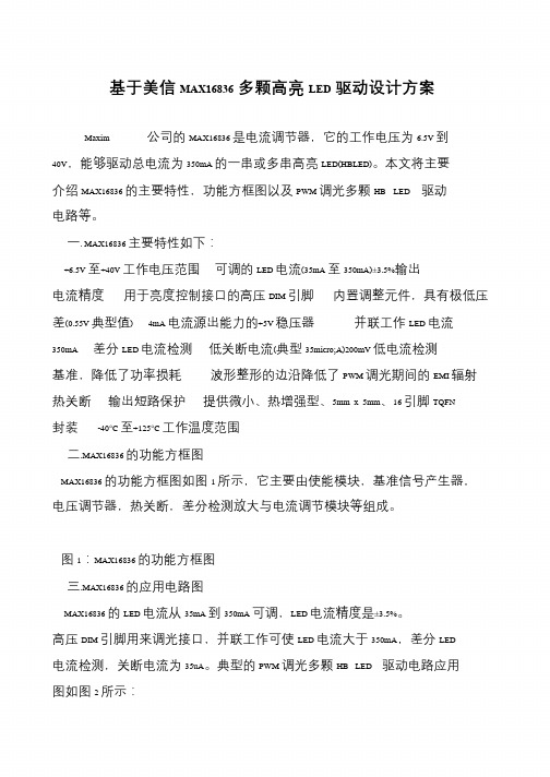
Maxim 公司的MAX16836 是电流调节器,它的工作电压为6.5V 到40V,能够驱动总电流为350mA 的一串或多串高亮LED(HBLED)。
本文将主要介绍MAX16836 的主要特性,功能方框图以及PWM 调光多颗HB LED 驱动电路等。
一. MAX16836 主要特性如下:
+6.5V 至+40V 工作电压范围可调的LED 电流(35mA 至350mA)±3.5%输出电流精度用于亮度控制接口的高压DIM 引脚内置调整元件,具有极低压差(0.55V 典型值) 4mA 电流源出能力的+5V 稳压器并联工作LED 电流350mA 差分LED 电流检测低关断电流(典型35micro;A)200mV 低电流检测基准,降低了功率损耗波形整形的边沿降低了PWM 调光期间的EMI 辐射热关断输出短路保护提供微小、热增强型、5mm x 5mm、16 引脚TQFN 封装-40°C至+125°C工作温度范围
二.MAX16836 的功能方框图
MAX16836 的功能方框图如图1 所示,它主要由使能模块,基准信号产生器,电压调节器,热关断,差分检测放大与电流调节模块等组成。
图1:MAX16836 的功能方框图
三.MAX16836 的应用电路图
MAX16836 的LED 电流从35mA 到350mA 可调,LED 电流精度是±3.5%。
高压DIM 引脚用来调光接口,并联工作可使LED 电流大于350mA,差分LED 电流检测,关断电流为35uA。
典型的PWM 调光多颗HB LED 驱动电路应用图如图2 所示:。
采用MAX16834设计的112W升压LED驱动器技术

采用MAX16834设计的112W升压LED驱动器技术MAX16834 是电流模式高亮LED(HBLED)驱动器,可用于升压,升压-降压,SEPIC和高边降压拓扑. 工作电压4.75V 到28V,3000:1 PWM调光/模拟调光,可编频率从100kHz到1MHz,主要用在单串LED LCD背光,汽车前后照明,投映系统RGB LED光源,点和环境照明以及DC/DC升压/升-降压转换器.本文介绍了MAX16834主要特性,方框图,多种应用电路以及112W升压LED驱动器参考设计,电路图和材料清单(BOM).图1.MAX16834内部方框图图2.MAX16834升压LED驱动器图3.MAX16834升压-降压LED驱动器(VLED+ < 28V)图4.MAX16834带汽车负载突变保护的升压LED驱动器图5.MAX16834高边降压LED驱动器图6.MAX16834升压DC/DC转换器图7.MAX16834升压-降压DC/DC转换器全陶瓷电容的112W升压长串LED驱动器参考设计112W boost driver for long strings of LEDs using all ceramic capacitorsThis is a reference design for a 112.5W boost LED driver that uses the MAX16834 for long strings of LEDs. These long LED strings are commonly found in streetlights and parking garage lights.Input voltage: 24VDC ±5% (at 1.49A)VLED configuration: Two parallel strings. Each string consists of 19 WLEDs and a 5Ω resistor for current balancing. Current is 750mA per sting for a total of 1.5A into 75V.Dimming: 50μs (min) on-pulse for up to a 200:1 dimming ratio with a 100Hz dimming frequency图8.112W升压长串LED驱动器参考设计外形图图9.112W升压长串LED驱动器参考设计电路图112W升压长串LED驱动器参考设计材料清单(BOM):。
MAX16818驱动高亮LED电路图

MAX16818驱动高亮LED电路图快速瓶劲识别-更好的负载测试方法高亮LED需用电流源而非电压源来驱动。
为了优化高亮LED驱动电路的设计,可采用改进后的降压-升压变换器拓扑,将串联的高亮LED串联于DC/DC变换器的输出端和输入电压源之间。
运用这种连接方式,可以为高亮LED串提供低于或高于输入电压的驱动电压。
降压-升压变换器的输入电流是非脉动方式,这不同于典型的降压-升压变换器的脉动输入电流,非脉动电流能有效降低EMI。
高亮LED驱动器的简化框图如图1所示,在该电路中,高亮LED端电压为图1 高亮LED驱动器的简化框图在平均电流控制模式下,输入电流的反馈电压可用检流电阻检测,如图2所示。
该电压送入电流误差放大器(CEA)的反相输入端。
放大器的同相输入端为电流的控制电压。
比较后的误差信号经过放大器放大后,送到PWM比较器的输入端,与斜坡信号进行比较。
电流环路的增益带宽特性可通过CEA附近的补偿网络进行优化。
图2 采用平均电流控制模式(内部环路)的高亮LED驱动器(1)电流环路补偿设计MAX16818采用平均电流模式控制器,利用跨导放大器(transconductance amplifier)放大电流误差信号。
检流电阻两端的电压由内部放大器放大34.5倍,电流误差放大器的跨导是550μS,锯齿波信号峰值为2V,输入电流在返回通路上由电阻Rs,检测。
利用MAX16818构成的高亮LED驱动器如图3所示。
图3 利用MAX16818构成的高亮LED驱动器高亮LED支路的最大电压为式中,而是LED的数目;UFm(IF)是LED在满负荷电流年下的最大压降。
最大输入功率为效率为η时,最大输入电流为检流电阻值由平均电流极限设置,最小平均电流阈值为24mV,因而,检流电阻值为为了避免控制器的PWM比较器输出自激,比较器反相输入信号的斜率应小于同相输入的锯齿波斜率。
锯齿波斜率为Us×fs盂,电流误差放大器的增益GCA为式中,gm是CEA的跨导。
MAX16821
只需增添三个功率MOSFET,单通道降压转换器即可驱动投影仪的RGB LED摘要:本应用笔记介绍了低功耗投影仪的RGB LED驱动器参考设计。
该设计利用单片MAX16821 HB LED驱动器在每一时刻驱动一个RGB LED。
这种方法减少了元件数量,获得高效、小巧且经济的设计。
文中给出了电路板布局和测试结果。
引言本应用笔记提供了一个低功耗投影仪RGB LED驱动器的参考设计。
基于单芯片MAX16821构建大电流LED驱动器,能够为一组降压驱动的RGB LED 提供高达10A的电流,通/断时间小于1µs。
某一时刻只驱动一个彩色LED,RGB按比例共用PWM周期。
LED驱动器技术指标•输入电源电压:10V至15V•LED驱动电流:10A•LED正向偏压:4.5V至6V•LED电流上升/下降时间:< 1µs•LED电流纹波:10%峰峰值,最大值输入•V IN (J4):电源输入•PWMR、PWMB、PWMG (J8的引脚1、3和4):RGB PWM输入信号,幅值应为3.3V至5V。
当输出的上升/下降时间保持在1µs以内时,任何超出2µs的PWM周期均可使用。
某一时刻只有上述三个信号之一为高电平。
•PWMN (J8的引脚4):PWMR、PWMG和PWMB进行逻辑NOR。
只有所有三个PWM信号均为低电平时,PWMN为高电平。
•ON/OFF (J1):保持开路或驱动至+5V使能驱动器,连接至GND禁用电路板工作。
输出•LEDR、LEDG、LEDB (J5、J6和J7):10A RGB LED输出。
将LED+连接至引脚3、4和5;将LED-连接至引脚6、7和8。
•OUTV (J2):提供与LED电流成比例的信号,OUTV上的电压为R12||R16电压的135倍。
•V IN_OUT (J3):输入电源电压,用于连接至其它电路板。
引脚1和2为V IN+;引脚3和4为GND。
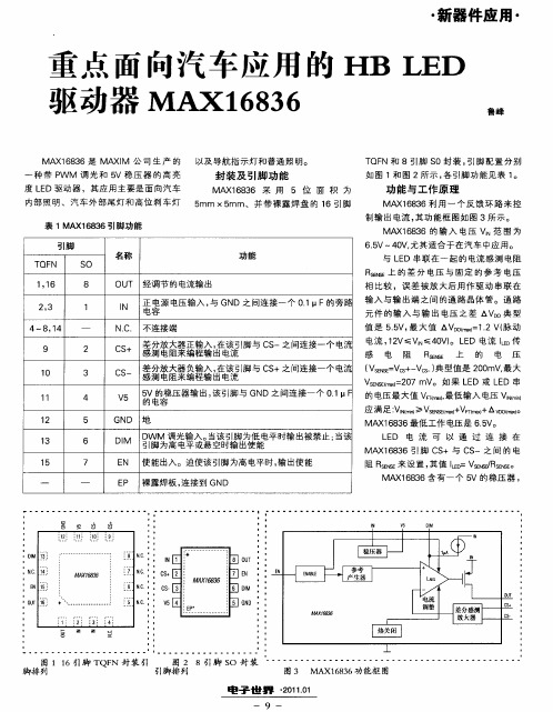
重点面向汽车应用的HBLED驱动器MAX16836
8
1
OU 经调节 的电流输 出 T
l N
相 比较 ,误差被 放大后 用作驱 动 串联 在
正 容 电压输入 , GN 与 D之间连接一个 01uF的旁路 输入 与输 出端之 间 的通 路 晶体 管。通 路 . 申 电源 元 件 的输入 与输 出 电压 之差 △V 0 型 D典
・
图 3 MA 63 X18 6功 能框 图
01101 电 子 世 界 2 .
—
9
・
新 器件应 用 ・
Vl_L D I M-
一
C
OT U OT U
OT U
E N
NC
DM l 6 D N
D 1
.
_
E N
NC . D M I
G Dl 2 N 1
D 1
』 E L D
O U
F ̄ Io J
I N
MA 6 3 X18 6
I N
v 1 5I1 。 一
C一 S
I N
7
v 5 匝 C匝 S .
c+ s
C 2 R ES SN E
c 2 『
P NE  ̄ S
f N
- N. 4 . 3 C
NC . NC . NC .
值 是 55 最 大 值 △V0 ) . 脉 动 .V, Dl =1 V《 2
4~8 1 ,4 9 2
N.. 不 连接 端 C
1 V≤VN 0 ) L D 电流 lD I ≤4 V 。 E L 传 E C + 差 分放 大 器 正 输 入 , 该 引脚 与 C 一之 间 连 接 一 个 电流 电流 ,2 S 在 S 感 测 电 阻来 编 程 输 出 电流 感 电 阻 RE S 怔 上 的 电 压
德州仪器MAX16826评估板使用手册说明书
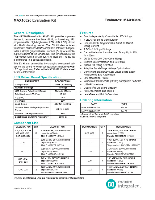
Evaluates: MAX16826MAX16826 Evaluation KitGeneral DescriptionThe MAX16826 evaluation kit (EV kit) provides a proven design to evaluate the MAX16826, a four-string, I 2C programmable high-brightness LED (HB LED) driver with PWM dimming control. The EV kit also includes Windows ® 2000/XP/Vista ®-compatible software that pro-vides a simple graphical user interface (GUI) for exercis-ing the features of the MAX16826. The MAX16826 EV kit PCB comes with a MAX16826ATJ+ installed. The EV kit is configured in a boost application.This EV kit can be modified by changing component val -ues on the board for other configurations (including RGB LED applications). Refer to the MAX16826 IC data sheet for more information.Features●Four Independently Controllable LED Strings ●7 LEDs Per String Configuration●Independently Programmable 50mA to 150mAString Current●7.5V to 22V Input Voltage●Can Withstand Automotive Load Dump Up to 40Vfor 400ms●0% to 100% DIM Duty Cycle Range ●Shorted LED Protection and Detection ●Open LED String Detection●Adaptive Boost-Stage Voltage Optimization●Convenient Breakaway LED Driver Board EasilyAdaptable to End Application ●Low Mechanical Profile●Windows 2000/XP/Vista (32-Bit)-Compatible Software ●USB-PC Interface●USB-to-I 2C On-Board Circuitry ●Fully Assembled and Tested ●Lead-Free and RoHS Compliant19-4271; Rev 1; 12/20Windows and Windows Vista are registered trademarks of Microsoft Corp.+Denotes lead-free and RoHS compliant.#Denotes RoHS compliant.PARAMETERDESCRIPTION Configuration 7 white LEDs/stringNumber of Strings4 strings LED Current Adjustment Range 50mA to 150mATotal Maximum LED Power 16.8W V IN (min)7.5V V IN (max)22V Load Dump40V for < 400ms Nominal Boost Voltage Adjustment Range22.4V to 32VNominal OVP Trip Threshold 35V Boost Stage Switching Frequency350kHzPARTTYPE MAX16826EVKIT+EV Kit MAX16826EVKIT#EV KitDESIGNATION QTY DESCRIPTIONC1, C2, C3, C5–C8, C12, C15,C17, C23, C2412100nF ±10%, 16V X7R ceramic capacitors (0603)TDK C1608X7R1C104K C9133nF ±10%, 50V X7R ceramic capacitor (0603)TDK C1608X7R1H333K C10, C11222pF ±5%, 50V C0G ceramic capacitors (0603)TDK C1608C0G1H220J C13, C14,C18–C2161μF ±10%, 16V X7R ceramic capacitors (0603)TDK C1608X7R1C105K C16, C25210μF ±10%, 10V X5R ceramic capacitors (1210)Murata GRM32FR61A106KDESIGNATION QTY DESCRIPTIONC26, C28210μF ±20%, 50V X5R ceramic capacitors (2220)Murata GRM55DR61H106K C27110μF ±20%, 50V X7S ceramic capacitor (1210)Taiyo Yuden UMK325BJ106MM-T C2912.2nF ±5%, 50V C0G ceramic capacitor (0603)Murata GRM1885C1H222K C3011μF ±10%, 50V X7R ceramic capacitor (1210)Murata GRM32RR71H105K C3214.7μF ±10%, 6.3V X5R ceramic capacitor (0603)Murata GRM188R60J475KLED Driver Board SpecificationOrdering InformationComponent ListClick here to ask about the production status of specific part numbers.DESIGNATION QTY DESCRIPTIONC3312200pF ±10%, 50V X7R ceramic capacitor (0402)Murata GRM155R71H222KC34, C35247μF ±20%, 50V electrolytic capacitorsPanasonic EEE-FK1H470XPC36, C370Not installed, capacitors (0603)C3811000pF ±5%, 50V C0G ceramic capacitor (0402)Murata GRM1555C1H102JA01DC391220pF ±5%, 50V C0G ceramic capacitor (0402)Murata GRM1555C1H221JC401100pF ±5%, 50V C0G ceramic capacitor (0402)Murata GRM1555C1H101JC41–C4440.01μF ±10%, 50V X7R ceramic capacitors (0402)Murata GRM155R71H103KC450Not installed, capacitor (0402)D1160V, 1A Schottky diode (SMB) Diodes, Inc. B160B-13-FJ11USB series-B right-angle PC-mount receptacleJ2, J30Not installed JU2–JU873-pin headersL11Ferrite bead (0603) TDK MMZ1608R301AL2122μH ±20%, 5A, 52mΩ inductor Coilcraft MSS1260-223MlLED11Red LED (0603) Panasonic LNJ208R8ARAP1, P22Connectors, FFC/FPC 18-pos, 1mm P31Connector, FFC/FPC 6-pos, 1mmQ1140V, 9A, 2.5W n-channel MOSFET (8 SO)International Rectifier IRF7469Q2–Q5455V, 1.9A, 160mΩ n-channel MOSFET s (SOT223) International Rectifier IRFL014NPbFR11220Ω ±5% resistor (0603)R21 2.2kΩ ±5% resistor (0603)R3, R9, R103 1.5kΩ ±5% resistors (0603) R4, R5227Ω ±5% resistors (0603)R61470Ω ±5% resistor (0603)R71100kΩ ±5% resistor (0603)R817.5kΩ ±1% resistor (0603)R11168Ω ±1%, 0.25W resistor (1206)DESIGNATION QTY DESCRIPTION R1210.04Ω ±1%, 0.5W sense resistor(2010)Vishay/Dale WSL2010R0400FEA R131215kΩ ±1% resistor (0402) R14, R16210kΩ ±1% resistors (0402) R151249kΩ ±1% resistor (0402)R171 1.27kΩ ±1% resistor (0603)R181182kΩ ±1% resistor (0603)R1912kΩ ±1% resistor (0402) R20, R22,R24, R264100kΩ ±1% resistors (0402) R21, R23,R25, R27416.5kΩ ±1% resistors (0402) R28–R3142.2Ω ±1%, 100mW sense resistors(0603)Panasonic ECG ERJ-3RQF2R2V R32, R3320Ω ±5% resistors (0603)R34–R3740Ω ±5% resistors (0402)R38112.1Ω ±1% resistor (0805)R391470Ω ±5% resistor (0402)R40110kΩ ±5% resistor (0603) R41–R444237kΩ ±1% resistors (0603) U11LED driver (32 TQFN)Maxim MAX16826ATJ+ U2, U82Microcontrollers (68 QFN-EP*)Maxim MAXQ2000-RAX+ U31UART-to-USB converter (32 TQFP)FTDI FT232BLU4193C46A 3-wire EEPROM (8 SO)Atmel AT93C46A-10SU-2.7 U51p-channel MOSFET power switch(8 SO)Maxim MAX890LESA+U61LDO regulator (5 SC70)Maxim MAX8511EXK25+T U71LDO regulator (5 SC70)Maxim MAX8511EXK33+T Y1120MHz crystal oscillatorY216MHz crystalHong Kong X’talsSSL6000000E18FAF—1Cable, flat flex 18-position, 1mm, 5in—7Shunts—1USB high-speed A-to-B cable,5ft (1.5m)—1PCB: MAX16828 Evaluation Kit+Component List (continued)*Exposed pad.Quick StartRecommended EquipmentBefore beginning, the following equipment is needed: ●MAX16826 EV kit (USB cable included)● A user-supplied Windows 2000/XP/Vista PC with a spare USB port●7V to 24V, 5A DC power supply●Four strings of white LEDs (7 LEDs/string)Note: In the following sections, software-related items are identified by bolding. Text in bold refers to items directly from the EV kit software. Text in bold and underlined refers to items from the Windows operating systemProcedureThe MAX16826 EV kit is fully assembled and tested. Follow the steps below to verify board operation:1) Visit /evkitsoftware to down-load the latest version of the EV kit software,16826Rxx.ZIP (xx in the filename denotes the soft -ware version number). Save the EV kit software to a temporary folder and uncompress the ZIP file.2) Install the EV kit software on your computer by run -ning the INSTALL.EXE program inside the temporary folder. The program files are copied and icons are created in the Windows Start | Programs menu.3) Verify that all jumpers (JU2–JU8) are in their defaultpositions, as shown in Table 1.4) Connect the USB cable from the PC to the EV kitboard. A New Hardware Found window pops up when installing the USB driver for the first time. If you do not see a window that is similar to the one described above after 30 seconds, remove the USB cable from the board and reconnect it. Administra-tor privileges are required to install the USB device driver on Windows.5) Follow the directions of the Add New HardwareWizard to install the USB device driver. Choose the Search for the best driver for your device option. Specify the location of the device driver to be C:\Program Files\MAX16826 (default installation direc-tory) using the Browse button. During device driver installation, Windows may show a warning message indicating that the device driver Maxim uses does not contain a digital signature. This is not an error condi-tion and it is safe to proceed with installation. Refer to the USB_Driver_Help.PDF document included with the software for additional information.6) Set the output of the power supply to 12V. Turn offthe power supply.7) Connect the positive terminal of the power supply tothe VIN pad of the LED driver board.Note: Indicate that you are using the MAX16826 when contacting these component suppliers.SUPPLIERPHONE WEBSITECoilcraft, Diodes, Inc.Hong Kong X’tals Ltd.852-******** International RectifierMurata Electronics North America, Panasonic Taiyo Yuden TDK Vishay/Dale402-563-6866FILE DESCRIPTIONINSTALL.EXE Installs the EV kit files on your computerMAX16826.EXE Application program FTDIBUS.INF USB device driver file FTDIPORT.INF VCP device driver file UNINST.INI Uninstalls the EV kit software USB_Driver_Help.PDFUSB driver installation help fileComponent SuppliersMAX16826 EV Kit Files8) Connect the negative terminal of the power supply tothe PGND pad of the LED driver board.9) Ensure that the supplied ribbon cable is firmly con -nected to the P1 and P2 connectors.10) Connect the anode ends of the LED strings to theP3-1 pin of the P3 connector.11) Connect the cathode ends of the LED strings to theP3-2 to P3-5 pins of the P3 connector.12) Turn on the power supply13) Start the MAX16826 EV kit software by opening itsicon in the Start | Programs menu. The EV kit soft-ware main window appears, as shown in Figure 1.14) Press the Start button to start the LED driver.15) Verify that all of the LEDs are lit.Table 1. MAX16826 EV Kit Jumper Descriptions (JU2–JU8)*Default position.JUMPER SHUNT POSITIONDESCRIPTIONJU21-2*On-board PWM signal for Ch12-3Connect user-supplied PWM signal for Ch1 to the on-board DIM1 pad JU31-2*On-board PWM signal for Ch22-3Connect user-supplied PWM signal for Ch2 to the on-board DIM2 pad JU41-2*MAX16826 SDA signal connected to on-board microcontroller 2-3Connect user-supplied SDA signal to the on-board SDA pad JU51-2*MAX16826 SCL signal connected to on-board microcontroller 2-3Connect user-supplied SCL signal to the on-board SCL pad JU61-2*MAX16826 SYNC/EN signal connected to on-board microcontroller 2-3Connect user-supplied SYNC/EN signal to the on-board SYNC/EN pad JU71-2*On-board PWM signal for Ch32-3Connect user-supplied PWM signal for Ch3 to the on-board DIM3 pad JU81-2*On-board PWM signal for Ch42-3Connect user-supplied PWM signal for Ch4 to the on-board DIM4 padDetailed Description of SoftwareThe MAX16826 evaluation kit software has all the functions to evaluate the MAX16826 IC. To start the MAX16826 EV kit software, click Start | Programs | Maxim MAX16826 Evaluation Kit | Maxim MAX16826 Evaluation Kit that is created during installation. The GUI main window appears as shown in Figure 1.Figure 1. MAX16826 EV Kit Software Main WindowString Current SetThe String Current Set group box is located at the upperleft corner of the main window. Use the scrollbars toadjust the current of the LED strings. The correspondingvalues of the current will be shown in the adjacent editboxes. Press the Read button to read the values from thelinear regulator output registers of the MAX16826. Theequivalent values of the output current will be shown inthe edit boxes.Boost Output ControlThe Boost Output Control Mode group box has thefunctions to control the boost output voltage.To control the boost output voltage manually, click on theradio button next to the Manual Control group box. Usethe scrollbar to adjust the output voltage, and the volt-age value will be displayed in the adjacent edit box. Theactual boost output voltage can be seen in the Read BackValues group box.To use the software automatic control, click on the radiobutton next to the Software Control group box. The editbox next to the Set button is used to change the Drain toGND regulated voltage of the current sink FETs on the LEDstring with the highest voltage drop. This voltage setting willdepend on how much overhead the user is willing to have.If the set value is too low, the LED currents will no longerbe well regulated and may indeed drop because the boostvoltage might fall too low. The scrollbar in this mode willmove automatically to compensate and regulate the outputvoltage. The update rate is approximately once per second.In any case, the channel with the lowest voltage across thesink FET will be regulated to the value in the edit box. DIM Pulse Width Modulation (DPWM)The DPWM group box is located at the center of the mainwindow. The four DIM PWM signals generated by theon-board MAXQ2000 microcontrollers are used to controlthe brightness of the LEDs. Adjust the scrollbars in theDPWM Duty Cycle group box to change the duty cycles of the PWM signals and the values of the duty cycle (%)are shown in the adjacent edit boxes. Check the Set AllChannels to 100% Duty Cycle checkbox to force all channel duty cycles to 100%.In the DPWM Frequency group box, change the DPWMfrequency by adjusting the scrollbar position and pressthe Set button. The frequency value will be shown in theedit box.To guarantee that the leading edge of all the DIM signalsare synchronized, press the Set button in the DPWMFrequency group box.Press the Start button to start to generate the PWM signals.Press the Stop button to stop all PWM signals.StatusThe Status group box is located at the right of the main window. The software reads the external FET drain voltage measurements, and the boost output voltage measurement from the ADC output registers of the MAX16826. The software multiplies the measured values by the appropriate scaling factor and then displays them in the Read Back Values group box.Enter the values into the edit boxes in the Fault Level Set group box to set the fault-detection values. When the value in the Read Back Values group box is less than the fault-detection value, then the color of the read-back value changes to dark green. When the read-back value is 0 to 10% higher than the fault-detection value, the read-back value turns a lime color. If the read-back value is more than 10% higher than the fault-detection value, then the read-back value turns purple. The read-back value turns red when it is more than 20% higher than the fault-detection value.The software also reads the fault register to detect the fault conditions. If a fault condition exists, it will be shown in the String Fault Status group box. See Table 2 for the fault-condition explanations.Press the Read button to update the Status group box. By checking the Automatic Read checkbox, the Status group box will be automatically updated every second. Enable/DisableThe Enable/Disable group box controls the signal on the SYNC/EN pin. Click on the Enable radio button to set the signal high and enable the MAX16826. Click on the Disable radio button to set the signal low and disable the MAX16826.StandbyCheck the Standby checkbox to set the MAX16826 to standby mode. Refer to the MAX16826 IC data sheet for more information regarding standby mode.Table 2. Fault Conditions*Open LED string detection may require multiple flag examination. FAULT NAME CONDITIONTOADC conversion timeout; alsocorresponds to open string condition* Open LED string openShort LED string shortedOVP OvervoltageScaling FactorsThe calculations for the LED string current, boost output voltage, and the read-back values are based on the scal-ing factors. You can change the scaling factor by select-ing the Scaling Factor menu item under the Scaling Factors menu bar. In the pop-up window shown in Figure 2, enter the appropriate scaling factor.See Table 3 for the formulas for the scaling factors. These values can be used for calibration against actual read values with external instruments.When the default values are changed, they are stored in the software. Re-enter the default values to bring the software back to the default setting.Table 3. Scaling FactorFigure 2. Scaling Factor WindowSCALING FACTOR FORMULADEFAULTVALUE DR1 (ADC read-back voltageacross Drain and GND for thesink FET on Ch1)1 + (R20/R21)7.046DR2 (ADC read-back voltageacross Drain and GND for thesink FET on Ch2)1 + (R22/R23)7.046DR3 (ADC read-back voltageacross Drain and GND for thesink FET on Ch3)1 + (R24/R25)7.046DR4 (ADC read-back voltageacross Drain and GND for thesink FET on Ch4)1 + (R26/R27)7.046Read Back VBoost (ADC read-back boost output voltage)1 + (R15/R16)25.900 String Current Set Ch1 (LEDstring current for Ch1)R31 2.200 String Current Set Ch2 (LEDstring current for Ch2)R30 2.200 String Current Set Ch3 (LEDstring current for Ch3)R29 2.200 String Current Set Ch4 (LEDstring current for Ch4)R28 2.200 VBoost (Boost output voltage) 1 + (R13/R14)22.500Detailed Description of HardwareThe MAX16826 EV kit board provides a proven layout for evaluating the MAX16826 IC. This EV kit consists of a controller board and an LED driver board. The break-away slots at the center of the EV kit make it easier for the user to break and separate the controller board from the LED driver board. This is done so that once the evaluation is complete with the included software, the driver board can easily be used in the target application environment with the target system microcontroller.To connect the power, ground, PWM, and the I2C inter-face signals of the boards, attach the ribbon cable to the P1 connector of the controller board and attach the other end of the ribbon cable to the P2 connector of the LED driver board.Controller BoardThe controller board acts as the bridge between the soft-ware in the PC and the actual LED driver board containing the MAX16826. In addition to the USB connectivity, it gen-erates the four adjustable PWM DIM signals that control the brightness of the LEDs. The controller board com-municates with the driver board through the I2C interface, and is able to read or change the values of the registers in the MAX16826.The user can use the MAX16826 evaluation kit software to control the controller board.See Table 1 to control the MAX16826 with a user-supplied PWM signal.LED Driver BoardThe LED driver board is able to drive up to four LED strings (7 LEDs/string). LED strings can be connected to the LED driver board through the P3 connector by using a ribbon cable. Connect all of the anode ends of the LED strings to the P3-1 pin (which connects to the boost out-put) of the P3 connector. Then connect the cathode ends of the LED strings to the P3-2 to P3-5 pins (that connects to the drains of the sink FETs) of the P3 connector. User-Supplied I2C InterfaceTo use the MAX16826 EV kit with a user-supplied I2C interface, install the shunts on pins 2-3 of JU4 and JU5. Connect SDA, SCL, and GND lines from the usersupplied I2C interface to the SDA, SCL, and PGND pads on the MAX16826 controller board.After the LED driver board has broken away from the controller board, the user may connect their supplied I2C, DIM, and power signals to the LED driver board through the P2 connector using a ribbon cable. See Table 4 for the pin description of the P2 connector.Table 4. Pin Description for P2 Connector PIN NUMBER DESCRIPTIONP2-1 to P2-5Connect to the VIN pin of the MAX16826 P2-6Not connectedP2-7 to P2-11Connect to the groundP2-12Connects to the SYNC/EN pin of theMAX16826P2-13Connects to the SDA pin of the MAX16826P2-14Connects to the SCL pin of the MAX16826P2-15Connects to the DIM4 pin of the MAX16826P2-16Connects to the DIM3 pin of the MAX16826P2-17Connects to the DIM2 pin of the MAX16826P2-18Connects to the DIM1 pin of the MAX16826Figure 3. MAX16826 EV Kit LED Driver Board SchematicFigure 4a. MAX16826 EV Kit Controller Board Schematic (Sheet 1 of 2)Figure 4b. MAX16826 EV Kit Controller Board Schematic (Sheet 2 of 2)Maxim Integrated cannot assume responsibility for use of any circuitry other than circuitry entirely embodied in a Maxim Integrated product. No circuit patent licenses are implied. Maxim Integrated reserves the right to change the circuitry and specifications without notice at any time.REVISIONNUMBERREVISION DATE DESCRIPTION PAGES CHANGED 009/08Initial release —112/20Updated Ordering Information 1Revision HistoryFor pricing, delivery, and ordering information, please visit Maxim Integrated’s online storefront at https:///en/storefront/storefront.html.。
- 1、下载文档前请自行甄别文档内容的完整性,平台不提供额外的编辑、内容补充、找答案等附加服务。
- 2、"仅部分预览"的文档,不可在线预览部分如存在完整性等问题,可反馈申请退款(可完整预览的文档不适用该条件!)。
- 3、如文档侵犯您的权益,请联系客服反馈,我们会尽快为您处理(人工客服工作时间:9:00-18:30)。
Maxim MAX16826高亮LED(HBLED)驱动方案
关键词:电源管理,LED驱动器,DC/DC转换器,HB LED
他高亮度LED MAX16826(HB LED)驱动器是专为汽车液晶显示器背光和其他显示应用,如工业或桌面显示器和液晶电视。
MAX16826集成开关稳压器控制器,一个4通道的线性电流驱动,模数转换器(ADC),和一个I2C接口。
IC 设计承受汽车抛负载高达40V的瞬态和冷起动条件下运行。
MAX16826包含一个电流模式PWM开关稳压控制器,调节输出电压的LED阵列。
开关稳压器部分配置为升压或SEPIC变换器及其开关频率可编程从100kHz 至1MHz。
MAX16826包括4通道可编程,故障保护,恒流源驱动控制器能够驱动所有的白色,RGB,RGB LED的配置或加琥珀。
每个通道的发光二极管的发光控制是由四个线性电流接收器中的每一个的直接调制信号来实现的。
一个内部的ADC 测量外部驱动晶体管的漏极电压和开关稳压器的输出。
然后这些测量可通过I2C 接口外部微控制器(μC)使输出电压优化LED的故障监测
在每一个线性的LED currentsink通道电流和开关稳压器的输出电压的幅值是使用I2C接口编程。
附加的功能包括:逐周期电流限制,短路LED串的保护,超温保护。
MAX16826在热增强可用,5mm x 5mm,32引脚薄型QFN封装,是指定在汽车40°C + 125°C温度范围。
MAX16826主要特性:
_外部MOSFET允许范围广泛的LED每串LED电流多
_单个PWM调光输入每串
_非常宽的调光范围
_ LED串短路和开路保护
_调节LED电流的上升/下降时间改善EMI控制
_单片机接口采用I2C允许
发光二极管的电压监测和优化
用一位内部ADC
短而开放的检测
串电流和输出电压的动态调整
待机模式
_集成升压/ SEPIC控制器
_外部开关频率同步
_ 4.75V至24V工作电压范围和承受40V的甩负荷_过压和过热保护
MAX16826应用:
LCD背光:
汽车信息娱乐显示器
汽车集群显示器
工业和台式电脑显示器
液晶电视
汽车照明:
自适应前照灯
低和高光束组件
图1。
MAX16826简化方框图
图2。
MAX16826开关稳压器控制方框图
图3。
MAX16826基于SEPIC的驱动器电路图
图4。
MAX16826典型应用电路图
MAX16826评估板
The MAX16826 evaluation kit (EV kit) provides a proven design to evaluate the MAX16826, a four-string, I2C programmable high-brightness LED (HB LED) driver with
PWM dimming control. The EV kit also includes Windows®
2000/XP/Vista®-compatible software that provides a simple graphical user interface (GUI) for exercising the features of the MAX16826. The MAX16826 EV kit PCB comes with a MAX16826ATJ+ installed. The EV kit is configured in a boost application.
This EV kit can be modified by changing component values on the board for other configurations (including RGB LED applications). Refer to the
MAX16826 IC data sheet for more information.
MAX16826评估板主要特性:
_ Four Independently Controllable LED Strings
_ 7 LEDs Per String Configuration
_ Independently Programmable 50mA to 150mA String Current
_ 7.5V to 22V Input Voltage
_ Can Withstand Automotive Load Dump Up to 40V for 400ms
_ 0% to 100% DIM Duty Cycle Range
_ Shorted LED Protection and Detection
_ Open LED String Detection
_ Adaptive Boost-Stage Voltage Optimization
_ Convenient Breakaway LED Driver Board Easily Adaptable to End Application
_ Low Mechanical Profile
_ Windows 2000/XP/Vista (32-Bit)-Compatible Software
_ USB-PC Interface
_ USB-to-I2C On-Board Circuitry
_ Fully Assembled and Tested
_ Lead-Free and RoHS Compliant
图5。
MAX16826评估板LED驱动器电路图
图6。
MAX16826评估板控制器板电路图(1)
图7。
MAX16826评估板控制器板电路图(2)MAX16826评估板材料清单(BOM):。