气控换向阀
versa valves维尔萨产品之铝合金气控或电磁换向阀
FeaturesMany Solenoid Electrical Connections— Conduit connection — Spade terminals — Wire leadsRegulator Plate — provides 4-way or 5-waypressure regulation.Complete range ofAC & DC voltages.— Air-Assisted Spring Return Air boosts spring for positive valve return.— Viton Packed Balanced SpoolAffords bubbletight sealing throughout entire pressure range. Bubbletight service reduces cost due to wasted air. Positive positioning of actuated device when utilizing 3-position valves.Forces required to actuate the valve are unaffected by the controlled pressure. Provides large compatibility range of media (air/inert gas) and air line lubricants.Rated for 20 million bubbletight cycles on lubricated service (10 million on non-lubricated service). Superior wear resistance characteristics.— Coil can be rotated 180 degrees for maximum application À exibility (non Plug-In valves).— DIN connectors with cord grip or conduit connection“Solenoid Pilot” — type Actuators Pressure beingcontrolled provides force to shift valve.Use of solenoid-pilot to control valve eliminatescoil burnout. Small residual pilot volume minimizeswasted air. Solenoid-pilot design reduces the powerconsumption required to shift and hold valve.Bleed Control Plate —Addition of a control plate for selected valves, allowsadjustable control of each exhaust port to provide accurate and inexpensive speed control .Large Flow Area Largest Cv rating for package size.C5= 0.75C7= 1.5C9= 4.1Provides faster cylinder response. Smaller size valve saves space.C9 NEMA 4 RatedIndividual —cylinder ports:Located in side &bottom of manifold.— Track Gasket Sealing Custom designedgaskets assure proper installation and apositive seal.— Circuit board with integral wiringt erminal strip provides fast andeasy installation.— 1/2” NPT Conduit connectionfor ease of wiring. One on each sideof manifold for mounting and wiringÀ exibility.Plug-In —Indicator LightsThe indicator lightoption allows electricalset-up, test and trouble shootingcapabilities, simplifying installation.Lights are easilyretro¿ tted in the ¿ eld.Junction boxes —can be retro¿ tted in the¿ eld.— Plug-In plate Connects valve to manifold.S ame junction box is utilized for both single anddouble solenoid valves. All coils are factorypre-wired to junction box.— Three Screws Fasten Valve to ManifoldE ase of installation and serviceability. No need tomake or break any plumbing connections. Simpleconnect/disconnect of electrical connections whenplug-in option is speci¿ ed.of conditions.Locating bosses —on manifold and end plateinterfaces assure properinstallation and sealing.— Integral SupportBracket Mounting Noextra parts or brackets are requiredin mounting complete valve/manifold assembly. Four veryassessable mounting bracketssimplify installation.“Ground” and Common”connections are pre-wired at factoryto common terminal screws and arecolor coded (green/white), reducinginstalled cost.Junction box doors and —screws are captive,reducingthe chance of losing parts, thereforesimplifying installation.The C3 is a four-way (5/2) body ported, two position valve, with #10-32 NPT ports standard and ISO G thread optional. It is actuated by single or double pilot (external) or single or double solenoid/pilot (internal). The pilot valve can be used as a ¿ve-way valve. A manual override for the solenoid operator is standard.The valves can be individually mounted as a side-ported valve or group mounted side by side using #6 screws. A 2- to 10-station manifold, providing common inlet and exhaust galleries, is available for rack mounting any combination of valves.À ow controlling element of each valve. The balanced spool allows the The C7 is a four-way manifold mounted and body ported, two/three position (5/2 5/3) valve,with ¼” NPT ports standard and ISO G thread optional. The manifold mounted vales are designed to be mounted on a stacking style manifold and can be manual, pilot or electrically operated with a variety coil options, as well as the Plug-In feature. An optional Pre-Wired subD connector can support up to 12 valves on a manifold.The body ported valves are of a universal Àow design, solenoid, manual or pilot operated and can be mounted individually or side by side using #8 screws or on a 2 to 10 station rack mounted manifold (for more information on manual and pilot actuated valves see page 9).The C5 is a four-way manifold mounted and body ported, two/three position (5/2 5/3) valve,with ǩ” NPT ports standard and ISO G thread optional. The manifold mounted valves are designed to be mounted on a stacking style manifold and can be manual, pilot or electrically operated with a variety coil options, as well as the Plug-In feature. An optional Pre-Wired sub D connector can support up to 12 valves on a manifold.The body ported valves are of a universal Àow design, solenoid, manual or pilot operated and can be mounted individually or side by side using #6 screws or on a 2 to 10 station rack mounted manifold (for more information on manual and pilot actuated valves see page 9). The C9 is a four-way manifold mounted and body ported, two/three position (5/2 5/3) valve, with ½” NPT ports standard and ISO G thread optional. The manifold mounted vales are designed to be mounted on a stacking style manifold and can be electrically operated with a variety coil options, as well as the Plug-In feature. An optional Pre-Wired Amphonal 19 pinconnector can support up to 8 valves on a manifold.The body ported valves are of a universal À ow design, solenoid, or pilot operated and can be mounted individually or side by side using ¼” screws (for more information on pilot actuated valves see page 9).Overrides Four types of overrides are available: Standard, Suf¿ x Detail -G, -M and -CML. The standard is a push twist to lock, requires no call out. -G is a guarded momentary contact, -M is an unguarded momentary contact and -CML is a raised grip, push twist to lock.Two styles are available depending on the solenoid pilot cap used; engineered polymer or aluminum. The engineered polymer (shown extreme left top to bottom) -CML, -M & standard. The aluminum (shown left top to bottom) -CML, -M, -G & standard (see electrical page 13 for applicable coil and override).TechnicalTemperatureAmbient Range -15ºC (5ºF) to +50ºC (125ºF)Flow C3: Cv (Kv) average all ports: 0.23 (3.3)C5: Cv (Kv) average all ports: 0.75 (11)C7: Cv (Kv) average all ports: 1.5 (22)C9:Cv (Kv) average all ports: 4.1 (59.5)Installation C Series valves have no limitations on mounting orientation.Filtration & Lubrication40 to 50 micron ¿ ltration, and use of general purpose, non-detergent lubricating oil (ISO, ASTM) Grade 32 in controlled air is recommended.Materials ValvesValve body, plunger - Anodized Aluminum Actuating caps: Solenoid (Standard) – Anodized Aluminum Solenoid (Low-Watt) - Synthetic Resin Spring Cap – Synthetic Resin Pilot Piston - Synthetic Resin Valve Seals: Plunger & Body - FKM (À uorocarbon) Pilot Piston - NBR (nitrile)Solenoid Parts (wetted) - 304, 430F Stainless Steel and Brass Screws - Stainless SteelPlug-In Plate - Synthetic ResinMaterials ManifoldsManifold, End Plates - Die cast Aluminum, powder coat-epoxy painted Bleed Control Plate, Junction Box - Synthetic Resin Regulator Accessory Plate - Black Anodized Aluminum Station Blank - Black Oxide Steel Track-gaskets - NBR (nitrile)Screws: Manifold to Manifold - Black Oxide St eel Valve to Manifold - Stainless Steel Valve Type Actuation Pilot Type Size SeriesOperating Pressure RangeAuxiliary Pilot Pressure5/2Single solenoidInpilotC325-115 psi (1.7-8 bar)none required Double solenoid-momentary contact 15-115 psi (1-8 bar)Single pilot-spring returnExpilotVacuum-115 psi (Vacuum-8 bar)Min Pilot 25 psi(1.7 bar)Double pilotVacuum-115 psi (Vacuum-8 bar)Min Pilot 15 psi(1 bar)5/2&5/3Single solenoidorSingle pilot-spring returnInpilotC515-115 psi (1-8 bar)none requiredC725-115 psi (1.7-8 bar)C930-150 psi (2.1-10.3 bar)Double solenoidorDouble pilot-springcenteredExpilotC5Vacuum-115 psi (Vacuum-8 bar)15-115 psi (1-8 bar)C7Vacuum-115 psi (Vacuum-8 bar)25-115 psi (1.7-8 bar)C9Vacuum-150 psi (Vacuum-10.3 bar)30-150 psi (2.1-10.3 bar)5/2Double solenoid-momentary contactInpilotC510-115 psi (0.7-8 bar)none required C715-115 psi (1-8 bar)C920-150 psi (1.4-10.3 bar)Double solenoid-momentary contactorDouble pilot-momentary pressureExpilotC5Vacuum-115 psi (Vacuum-8 bar)10-115 psi (0.7-8 bar)C715-115 psi (1-8 bar)C9Vacuum-150 psi (Vacuum-10.3 bar)20-150 psi (1.4-10.3 bar)5/2&5/3Manual-Lever, Button or Rotary switchC5Vacuum-115 psi (Vacuum-8 bar)not applicableC7SelectorManifold SelectorValve SelectorBEB EAIN AABEBEAINAABBEBEAINAABBEBEAINAABBEBEAINAABNotes:*Voltage options - see page 14-15**Low watt option (DC - 027, AC - 043 or none)† The number of stations - 2-12½” manifold limited to 8 stations with multi pin connector †† None Non Plug-In manifold P Plug-In manifoldPL Plug-In manifold with lights*PM Multi-Pin connector left hand sidePML Multi-Pin connector left hand side with lights* PMR Multi-Pin connector right hand sidePMLR Multi-Pin connector right hand side with lights**Lights require same voltage option as Solenoidvalve being usedManifold, Rack MountedRack Mounted ManifoldNumber of StationsManifold Part Number by Port Sizeǩ” Ports¼” Ports Ǫ” Ports 2CM-4200-2C5M-4200-2C7M-4400-23CM-4200-3C5M-4200-3C7M-4400-34CM-4200-4C5M-4200-4C7M-4400-45CM-4200-5C5M-4200-5C7M-4400-56CM-4200-6C5M-4200-6C7M-4400-67CM-4200-7C5M-4200-7C7M-4400-78CM-4200-8C5M-4200-8C7M-4400-89CM-4200-9C5M-4200-9C7M-4400-910CM-4200-10C5M-4200-10C7M-4400-10Mountable Solenoid Valves†CSG-4122-027-(*)CSG-4122-043-(*)CGG-4122-027-(*)CGG-4122-043-(*)CSG-4222-(**)-(*)CGG-4222-(**)-(*) CXX-4223-(**)-(*) CXX-4224-(**)-(*) CXX-4228-(**)-(*)CSG-4322-(**)-(*)CGG-4322-(**)-(*)CXX-4223-(**)-(*)CXX-4224-(**)-(*)CXX-4228-(**)-(*)BEBEAIN ABEBEAINABEB EAINAB EB EAIN AB EB EAIN AB EB EAIN AB EB EAINAB EB EAINABEB EAIN AB EB EAIN AB EB EAIN AB EB EAIN AB EB EAIN AIndicator lightsIndicator lights are available in conjunction with the Plug-In electrical connection for all common voltages and are located in the cover of each junction box. These lights allow for easy manifold set-up and trouble shooting (see voltage codes page 6).I ntermediate Supply ManifoldsIn applications where air À ow capacity might be compromised due to several valves functioning at the same time or where controlled accessories require large volumes, Intermediate Supply Manifolds can be inserted into the manifold assembly at strategic intervals and additional inlet supply can be connected to these Supply Ports in order to increase the available volume of air. Consult factory for application assistance.Bleed Control PlatesBleed Control Plates that provide speed control through metering of the exhausts can be added as an option for any valve stations that require this feature (see page 12).Isolation Disc (Suf ¿ x-XS_)Isolation Discs are small gasketed shields that can be placed between manifold stations, to ef-fectively isolate each group of valves that utilize the same pressure. For example, a ¿ ve station assembly could have two stations functioning at 50 psi and three stations functioning at 100 psi by simply placing an Inlet Isolation Disc at the intersection of valve station 2 & 3 (see page 6).¿ c C5, C7 or C9 series. Different types ¿ eld, or at any time, by addition or subtrac-Plug-In electrical connection (Suf ¿ x -P)Use of the Plug-In electrical connection option simpli ¿ es wiring, installation and servicing. Wiring connections are made within a junction box adapter so that there is no hard wiring to any valve. Installation or removal of a valve, accomplished by simply loosening or tightening 3 valve mounting screws, and the valve is disconnected pneumatically and electrically.The grounds and commons are pre-wired at the factory, so that only one wire connection is necessary for each solenoid and this is further simpli ¿ ed by a unique terminal strip mounted in the end cover of each box.Voltage Surge Protection (Suf ¿ x -SSD)Surge limiting diodes are available for DC circuits (see pages 6 & 14).Multi-Pin Connector (Suf ¿ x -PM)The Multi-Pin option utilizes a 25 pin plug (male side) Sub-D connector on the C5 and C7 and a 19 pin, NEMA 4 connector on the C9; all are pre-wired and factory tested. All stations on Multi-Pin connector equipped manifolds are always wired for double solenoid valves, whether the valves are single or double solenoid. This allows the pneumatic equipment designer to change valve function easily if design changes occur.Connection to a programmable logic controller is possible without the normal labor cost associated with solenoid valve wiring. Remove three screws and the valve is removed from the manifold without touching any electrical or pneumatic connections (see notes page 8 for additional suf ¿ x details and page 14 for individual pin identi ¿ cation).RegulatorsSandwich regulators complete with pressure gauge with inlet port pressure for 4-way function on any valve stations that require this feature. Dual pressure for 5-Way regulators also available (see full description on page 11).Spacer PlateRequired on C5 & C7 stacking manifold for mounting adjacent valves with hazardous service electrical operators or when mounting side by side regulators (see page 12).RegulatorsFlow Diagram above shows one single solenoid valve mounted on the Regulator Assembly.Flow Diagram above shows one single solenoid valve mounted on the Regulator Assembly. Supply Main pressure is supplied to the ‘EB’ (5) port and Regulated pressure is supplied to the ‘EA’ (3) port.SINGLE PRESSURE (4-WAY) REGULATOR FLOW DIAGRAMDUAL PRESSURE (5-WAY) REGULATOR FLOW DIAGRAMNotes:1) Regulator Assembly includes gauge, valve mounting screws and track-gasket.2) For side by side mounting of regulators or for regulators on every station, consult factory.3) Regulators for use with INPilot type valves only.4) For 4-way type regulator, must specify 4-way valve. For 5-way type regulator, must specify 5-way valve. Change ¿ rst 4 invalve part number to 5, for example, CSG-4332-043 changes to CSG-5332-043.5) Minimum manifold inlet pressure based on valve type.Metric dimensions in mm shown in parenthesis.DimensionsSeries A B C C5 3.79”(96.3) 1.25”(31.6)8.94”(227.1)C74.13”(104.9) 1.5”(38.1)8.85”(224.8)C95.33”(135.4)2.14”(54.4)13.67”(347.2)Plug-In Manifold Bleed ControlExtruded Manifold Bleed ControlC5: C5M-BC4C7: C7M-BC4Plug-In Manifold Station BlankExtruded Manifold Station BlankC5: C5M-SB4C7: C7M-SB4Plug-In Manifold Spacer PlateRegulators & AccessoriesMetric dimensions in mm shown in parenthesis.NOTES:1) Regulator Assembly includes valve mounting screws and O-rings and can only be mounted on every other station. Alternate regulator assemblies for adjacent stations.2) All valves must be EXPilot type. No auxiliary pilot pressure required (see diagrams).3) Minimum manifold inlet pressure required is based on valve type. See Technical Information page 5.4) C7 only: regulator assembly product numbers listed are for use with Expilot solenoid operated valves only. For pilot or lever operated valves add “P” to the product number shown. FOR EXAMPLE: C7AR-4010GP 5) C7 only: assemble the adapter assembly À ush in the pilot port of solenoid valve using a 9/16” wrench.4 way5 WAY (Dual pressure 4-Way)Pressure Range psi C5C7C5C7C5AR-4010G C7AR-4010G C5AR-5010G C7AR-5010G 1-10C5AR-4030G C7AR-4030G C5AR-5030G C7AR-5030G 3-30C5AR-4060G C7AR-4060G C5AR-5060G C7AR-5060G 5-60C5AR-4125GC7AR-4125GC5AR-5125GC7AR-5125G10-125DimensionsSeriesA B C C52.12”(53.8) 1.25”(31.8) 6.79”(172.5)C72.27”(57.7)1.7”(42.4)8.66”(220)HazardousServiceand non Plug-In Valves C5C5M-SP4M 0.55” wide C7C7M-SP4M 0.40” wide Plug-InValvesC5C5M-SP4M-P 0.55” wide C7C7M-SP4M-P0.40” wideC5C5M-BC4MC5M-BC4M-P For Low Watt Plug-In valves C7C7M-BC4MC7M-BC4M-P For Low Watt Plug-In valves C9C9M-BC4MC9M-BC4M-P For Low Watt Plug-In valvesC5C5M-SB4M C7C7M-SB4M C9C9M-SB4M3 spade terminals ,11 mm, for use with Mini DINconnector (DIN 43650 Form “B”). Pg9 cord grip NEMA 4. UL CSA 3 spade terminals 11 mm, for use with ½” NPT Mini DIN connector. (DIN 43650 Form “B”). Two leads (½” NPT conduit entry; integrally molded coil & conduit entry, NEMA 4/IP65. 3 spade terminals, 11 mm, Mini DIN for use with Versa socket on Plug-In manifolds C9. (DIN 43650 Form “B”) NEMA 4/IP65. Overrides G, M, & CML*Coil 3 spade terminals, 8 mm, Micromini DIN (DIN 43650 Form “C”). Coil with 3 spade terminals, 8 mm, Micromini DIN for use with Versa socket on Plug-In manifoldsC5 & C7 (DIN 43650 Form “C”). Overrides M & CML*ElectricalMULTI PIN CONNECTORSC9C5&C7Surge Suppression DiodeC5, C7 & C9Wire Location 19 Pin CONNECTOR Pin No.Wire No.Function 12346891011131415161718195127VIOLET RED GREY RED/BLUE GREEN WHITE/GREEN WHITE/YELLOW WHITE/GREYBLACKYELLOW/BROWN BROWN/GREENWHITE YELLOW PINKGREY/BROWN GRAY/PINK BLUEGREEN/YELLOWBROWNValve 1, SOL A12Valve 1, SOL B14Valve 2, SOL A12Valve 2, SOL B14Valve 3, SOL A12Valve 3, SOL B14Valve 4, SOL A12Valve 4, SOL B14Valve 5, SOL A12Valve 5, SOL B14Valve 6, SOL A12Valve 6, SOL B14Valve 7, SOL A12Valve 7, SOL B14Valve 8, SOL A12Valve 8, SOL B14COMMON GROUNDNONEWire Location DB 25 CONNECTOR Pin No.Wire No.Function 11421531641751861972082192210231124122513112233445566778899101011111212CValve 1, SOL A12Valve 1, SOL B14Valve 2, SOL A12Valve 2, SOL B14Valve 3, SOL A12Valve 3, SOL B14Valve 4, SOL A12Valve 4, SOL B14Valve 5, SOL A12Valve 5, SOL B14Valve 6, SOL A12Valve 6, SOL B14Valve 7, SOL A12Valve 7, SOL B14Valve 8, SOL A12Valve 8, SOL B14Valve 9, SOL A12Valve 9, SOL A14Valve 10, SOL A12Valve 10, SOL B14Valve 11, SOL A12Valve 11, SOL B14Valve 12, SOL A12Valve 1, SOL B14COMMON12345678910111213141516171819202122232425A 1214B V dc++-DimensionsMetric dimensions in mm shown in parenthesis.Manifolds, StackingC5, C7 & C9 Stacking Manifolds DimensionsSERIESABCDEFGHICylinder Ports Inlet PortsConduitHub C51” (25.4).95”(24.1)7.40”(188.1) 4.76”(121.0).33”(8.4) 2.60”(66.0) 5.35”(135.9) 3.79”(96.3) 2.00”(50.8)Side ¼”NPT½”NPTǩ” or ¼”Bottom ǩ”C71” (25.4) 1.12” (28.5)8.03” (204) 5.39”(136.9).33”(8.4) 3.24” (82.4) 6.00” (152.4) 3.7”(82.4) 2.00”(50.8)SideǪ”NPT ½”NPT¼” or Ǫ”Bottom ¼”C91.75”(44.5)2.18”(55.4)10.75”(273.1)7.32”(185.9)0.25”(6.4)7.88”(200.2)NA7.86”(199.6) 3.20”(81.28)Side¾”NPT 1”NPT½”Bottom½”Valves, Sideported*Indicate number of stations, 2 to 10NOTE: manifolds available with ISO threads, consult factory.NOTE: valves available with ISO threads,consult factory.A A*BCDE Port SizeMountingHoles DiameterC3 3.93”(99.8) 5.80”(147.2)1”(25.4)0.67”(17) 2.01”(51) 2.09”(26.7)10-32” NPT (M5 X 0.8)0.147”# 6 Screw C5 5.03” (127.7)7.92” (201.2) 1.25” (31.8) 0.88” (22.4) 1.46” (37.2) 3.71” (94.2) ǩ” NPT (G ǩ) 0.144”#8 Screw C7 5.65” (143.6) 8.55” (217.1) 1.50” (38.1) 1.06” (27.0) 1.59” (40.4) 4.02” (102.2) ¼” NPT (G¼) 0.172”#8 Screw C97.45”(189)10.75”273 2.25”(57) 1.75”(44) 2.25”(57) 2.57”(63)½” NPT (G½)0.27”¼” ScrewFixed Length Manifold Part NumberValve SeriesPart NumberPort SizeC3C3M-4200-(*number of stations)ǩ” NPT C5C5M-4300-(*number of stations)¼” NPT C7C7M-4400-(*number of stations)Ǫ” NPTMounting Holes 4C3 .144” 3.7mm C5 .172” 4.4mm C7 .265” 6.7mmDimensionsValves, Pilot & ManualLever ActuatedButtonActuatedRotary Switch Actuated**For Option -25B Large button.Metric dimensions in mm shown in parenthesis.Metric dimensions in mm shown in parenthesis.NOTE: valves available with ISO threads, consult factory.AA*B C DD**Large ButtonEE*FInlet, Exhaust, & Cylinder PortsButton Actuated Valves C5 4.37”(111.0) 4.66” 118.4 1.25” (31.8)0.88”(22.2) 1.38”(35.1) 1.81”(46.0)0.88”(22.4)0.17”(4.3)0.56 ”(14.2)ǩ” NPT G ǩC74.99”126.8 ()5.28” (134.1) 1.50” (38.1) 1.06” (27.0)1.38” (35.1) 1.81” (46.0)0.88”(22.4)0.17”(4.3)0.56 ” (14.2) ¼” NPT G¼Rotary Switch Actuated Valves C53.96” (100.6)-- 1.25” (31.8)0.88”(22.2)----0.78”(19.8)-- 2.00”(50.8)ǩ” NPT G ǩC7 4.58 ”(116.3)-- 1.50”(38.1) 1.06”(27.0)----0.78”(19.8)-- 2.62”(67.0)¼” NPT G¼Lever ActuatedValves C5 4.04”(102.7)-- 2.63”(66.8)0.88”(22.2)----------ǩ” NPTG ǩC7 4.04”(102.7)-- 2.75”(65.9) 1.06”(27.0) ----------¼” NPTG¼A A*BC DPressurePilot PortInlet, Exhaust, &Cylinder PortsC3 2.32”(58.92) 2.57”(62.28) 1.00”(25.4)0.67”(17)10-32” NPT (M5 X 0.8)10-32” NPT (M5 X 0.8)C5 3.44”(87.3) 4.75”(120.7) 1.25”(31.8)0.88”(22.2)ǩ” NPT (G ǩ)ǩ” NPT (G ǩ)C7 4.06”(103.2) 5.38”(136.6) 1.50”(38.1) 1.06”(27.0)ǩ” NPT (G ǩ)¼” NPT (G¼)C95.88”(149)7.88”(200) 1.73”(43.9) 2.0”(50.8)ǩ” NPT (G ǩ)½” NPT (G½)WARNINGS REGARDING THE DESIGN APPLICATION,INSTALLATION AND SERVICE OF VERSA PRODUCTSThe warnings below must be read and reviewed before designing a system utilizing, installing, servicing, or removing a Versa product. Improper use, installation or servicing of a Versa product could create a hazard to personnel and property.DESIGN APPLICATION WARNINGSVersa products are intended for use where compressed air or industrial hydraulic À uids are present. For use with media other than speci ¿ ed or for non-industrial applications or other applications not within published speci ¿ cations, consult Versa.Versa products are not inherently dangerous. They are only a component of a larger system. The system in which a Versa product is used must include adequate safeguards to prevent injury or damage in the event of system or product failure, whether this failure be of switches, regulators, cylinders, valves or any other system component. System designers must provide adequate warnings for each system in which a Versa product is utilized. These warnings, including those set forth herein, should be provided by the designer to those who will come in contact with the system.Where questions exist regarding the applicability of a Versa product to a given use, inquiries should be addressed directly to the manufacturer. Con ¿ rmation should be obtained directly from the manufacturer regarding any questioned application prior to proceeding.INSTALLATION, OPERATION AND SERVICE WARNINGSDo not install or service any Versa product on a system or machine without ¿ rst depressurizing the system and turning off any air, À uid, or electricity to the system or machine. All applicable electrical, mechanical, and safety codes, as well as applicable governmental regulations and laws must be complied with when installing or servicing a Versa product.Versa products should only be installed or serviced by quali ¿ ed, knowledgeable personnel who understand how these speci ¿ c products are to be installed and operated. The individual must be familiar with the particular speci ¿ cations, including speci ¿ cations for temperature, pressure, lubrication, environment and ¿ ltration for the Versa product which is being installed or serviced. Speci ¿ cations may be obtained upon request directly from Versa. If damages should occur to a Versa product, do not Operate the system containing the Versa product. Consult Versa for technical information.LIMITED WARRANTY DISCLAIMER AND LIMITATION OF REMEDIES Versa’s Series products are warranted to be free from defective material and workmanship for a period of ten years from the date of manufacture, provided said products are used in accordance with Versa specifications. Versa’s liability pursuant to that warranty is limited to the replacement of the Versa product proved to be defective provided the allegedly defective product is returned to Versa or its authorized distributor. Versa provides no other warranties, expressed or implied, except as stated above. There are no implied warranties of merchantability or fitness for aparticular purpose. Versa’s liability forbreach of warranty as herein stated isthe only and exclusive remedy and in no event shall Versa be responsible orliable for incidental or consequentialdamages.Versa Products Company Inc.22 Spring Valley RoadParamus, New Jersey 07652USAPhone: 201-843-2400Versa BVPrins Willem Alexanderlaan 14297321 GB Apeldoorn The NetherlandsPhone: 011-31-55-368-1900。
气动控制阀结构与原理

1.方向控制阀及换向回路方向控制阀按气流在阀内的作用方向,可分为单向型控制阀和换向型控制阀。
(1)单向型控制阀。
1)单向阀。
气动单向阀的工作原理与作用与液压单向阀相同。
在气动系统中,为防止储气罐中的压缩空气倒流回空气压缩机,在空气压缩机和储气罐之间就装有单向阀。
单向阀还可与其他的阀组合成单向节流阀、单向顺序阀等。
2)梭阀(或门阀)。
梭阀是两个单向阀反向串联的组合阀。
由于阀芯像织布梭子一样来回运动,因而称之为梭阀。
图3一25(a)为或门型梭阀的结构图。
其工作原理是当P1进气时,将阀芯推向右边,P2被关闭,于是气流从P1进人A腔,如图3-25(b)所示;反之,从P2进气时,将阀芯推向左边,于是气流从几进人P2腔,如图3-25(c)所示;当P1,P2同时进气时,哪端压力高,A就与哪端相通,另一端就自动关闭。
可见该阀两输人口中只要有一个输人,输出口就有输出,输人和输出呈现逻辑“或”的关系。
或门型梭阀在逻辑回路中和程序控制回路中被广泛采用,图3-26是梭阀在手动一自动回路中的应用。
通过梭阀的作用,使得电磁阀和手动阀均可单独操纵汽缸的动作。
气动调节阀:/3)双压阀(与门阀)图3-27是双压阀的工作原理图。
当P1进气时,将阀芯推向右端,A 无输出,如图3-27(a)所示;当P2进气时,将阀芯推向左端,A无输出,如图3一27(b)所示;只有当P1,P2同时进气时,A才有输出,如图3-27(c)所示;当P1和P2气体压力不等时,则气压低的通过A输出。
由此可见,该阀只有两输人口中同时进气时A才有输出,输人和输出呈现逻辑“与”的关系。
自力式压力调节阀:/双压阀的应用很广泛,如图3一28所以是在互锁回路中的应用。
只有工件的定位信号1和夹紧信号2同时存在时,双压阀才有输出,使换向阀换向,从而使钻孔缸进给。
4)快速排气阀。
用于使气动元件或装置快速排气的阀叫作快速排气阀,简称快排阀。
通常汽缸排气时,气体是从汽缸经过管路,由换向阀的排气口排出的。
第三章 气动控制元件
梭阀的应用实例
用两个手动按钮1S1和1S2操纵气缸进 退。当驱动两个按钮阀中的任何一个 动作时,双作用气缸活塞杆都伸出。 只有同时松开两个按钮阀,气缸活塞 杆才回缩。
梭阀主要用于选择信号,如应用于手动 和自动操作的选择回路。当管接头等选 用不当时,造成某通口的进气量或排气 量非常小时,阀芯可能会换向不到位, 造成路路通现象,必须防止。此外梭阀 也可用于高低压转换回路。
1.减压阀pressure reducing valve 作用: 减压、稳压
图形符号
减压阀(调压阀)是将较高的入口压力 调节并降低到符合使用的出口压力,并 保持调节后出口压力的稳定。 减压阀按压力调节方式可分为直动式和 先导式;按溢流结构分为溢流式、非溢 流式和恒量排气式三种。
减压阀溢流口结构
6.气动逻辑元件
含义:通过元件内部的可动部件的动 作改变气流方向来实现一定逻辑功能 的气动控制元件。 特点:抗污染能力强,无功耗气量 低,带负载能力强。
分类:
Байду номын сангаас按工作压力分
高压元件(工作压力0.2~0.8MPa) 低压元件(工作压力0.02~0.2MPa) 微压元件(工作压力0.02MPa以下)
按逻辑功能分
双压阀的应用实例
只有当两个按钮阀1S1和1S2都压下 时,单作用气缸活塞杆才伸出。若 二者中有一个不动作,则气缸活塞 杆将回缩至初始位置。
4、快速排气阀 (quick exhaust valve)
快排阀是为使气缸 快速排气,加快气 缸运动速度而设置 的专用阀,安装在 换向阀和气缸之间。
原理:当P口进气时, 推动膜片向下变形,打开P与A的通路,关闭O口;当P 口没有进气时,A口的气体推动膜片复位,关闭P 口,A口气体经口快速排出。
气控系统基本元件和基本回路
起减压和稳压作用。
▪ 油雾器
特殊的注油装置。当压缩空气流过时,它将润滑油喷射成雾 状,随压缩空气流入需要的润滑部件,达到润滑的目的。
气动三大件
▪ 气动三大件的安装连接次序:分水过滤器、减压阀、
油雾器。多数情况下,三件组合使用,也可以少于三 件,只用一件或两件。
气动执行元件
分类----气缸、气马达。 气缸的分类及典型结构
► 过载保护回路
正常工作时,阀1得 电,使阀2换向,气缸 活塞杆外伸。如果活 塞杆受压的方向发生 过载,则顺序阀动作, 阀3切换,阀2的控制 气体排出,在弹簧力 作用下换至图示位置, 使活塞杆缩回。
力控制回路
气动系统一般压力较低,所以往往是通过改变执行元 件的受力面积来增加输出力。
▪ 串联气缸回路
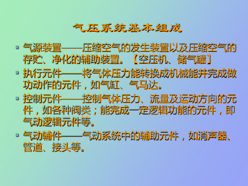
气源装置
► 气源装置为气动系统提供满足一定质量要求的压 缩空气,是气动系统的重要组成部分。
► 气动系统对压缩空气的主要要求:具有一定压力 和流量,并具有一定的净化程度。
► 气源装置由以下四部分组成 ▪ 气压发生装置——空气压缩机; ▪ 净化、贮存压缩空气的装置和设备; ▪ 管道系统; ▪ 气动三大件。
速度控制回路
► 气动系统功率不大,主要用节流调速的调速方法。
▪ 气阀调速回路
单作用气缸调速回路 用两个单向节流阀分别控制 活塞杆的升降速度。
▪ 排气节流阀调速回路
通过两个排气节流阀控制气缸伸 缩的速度。
速度控制回路
▪单作用气缸快速返回回路
活塞返回时,气缸下腔通 过快速排气阀排气。
▪ 缓冲回路
活塞快速向右运动接近末 端,压下机动换向阀,气体经 节流阀排气,活塞低速运动到 终点。
▪ 后冷却器——将空气压缩机排 出具有140℃~170℃的压缩空气 温度降至40℃~50℃,并使压缩 空气中的油雾和水气也凝析出来。 冷却方式有水冷式和气冷式两种。
气动控制基本回路
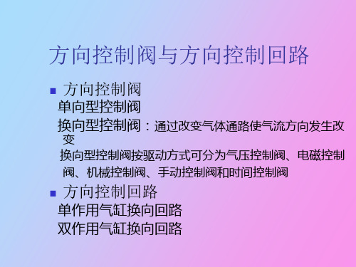
方向控制阀
单向型控制阀 换向型控制阀:通过改变气体通路使气流方向发生改
变 换向型控制阀按驱动方式可分为气压控制阀、电磁控制 阀、机械控制阀、手动控制阀和时间控制阀
方向控制回路
单作用气缸换向回路 双作用气缸换向回路
单向型控制阀
单向阀:气流只能向一个方向流动而不能反向流动通 过的阀
AB
1
2
1
2
AB
O1 P O2 a)
O1 P O2 b)
P c)
双电磁铁直动式换向阀工作原理图 图17-10
换向型控制阀
时间控制换向阀:使气流通过气阻(如小孔、缝隙等)
节流后到气容(储气空间)中,经过一定时间气容内建立起一定 的压力后,再使阀芯动作的换向阀
K
A
a
POK
延时换向阀 图17-11 延时换向阀 图17-11
“是门”(S=A) “或门”(S=A+B ) “与门”(S=A·B) “非门”(S= Ã)元件 双稳元件
按结构形式分:
截止式 膜片式 滑阀式
或门:S=A+B
或门元件 图17-33 或门元件 图17-33
是门:S=A 与门:S=A·B
A
P(B)
图17-34是门和与门元件 是门和与门元件 图17-34
YT4543动力滑台液压系统:电磁铁动作表、基本回路、 工作原理、特点
气液速度控制回路 图17-32
气动逻辑元件(又称逻辑阀)
工作原理:
均是用压缩空气为工作介质,通过元件内部可动部 件的动作,改变气流方向,从而实现逻辑控制功能
气动逻辑元件的分类
按工作压力分:
高压元件(0.2~0.8MPa ) 低压元件(0.02~0.2MPa ) 微压元件(〈0.02MPa)
第十四章 气动控制元件

为防止爬行,提高运动平稳性,使用 气动流量控制阀调速应注意以下几点: ①管道不能有漏气现象。 ②气缸、活塞间的润滑状态要好。 ③流量控制阀应尽量安装在气缸或气马达 附近。 ④尽可能采用出口节流调速方式。 ⑤外加负载应当稳定。若外负载变化较大, 应借助液压(如气液联动)或机械装置来 补偿由于载荷变动造成的速度变化。
压力控制可分为三类:一类是起
降压稳压作用的减压阀 减压阀、定值器,一类 减压阀 安全阀、限压 是起限压安全保护作用的安全阀 安全阀 切断阀等;一类是根据气路压力不同进 行某种控制的顺序阀 顺序阀、平衡阀等。 顺序阀
14.1.1 安全阀
14.1.2 减压阀
在气压传动系统中,空气压缩机将空 气压缩、净化后,储存在压缩空气站的储气 罐中,经管路输送给气压子系统的分储气罐 。而储气罐的空气压力比各台设备实际所需 的压力高,同时其压力波动值也较大。 为此常用减压阀(调压阀) 减至各设备 所需的压力,并稳定在一定压力值上。 减压阀是气动三大(联)件的组成元件
3.非门和禁门元件 非门和禁门元件
4 或非元件
5.双稳元件 双稳元件
双稳元件属记忆元件,在逻辑回路中 起着重要的作用。
14.4.3. 高压膜片式逻辑元件
利用膜片式阀芯的变形来实现各种逻 辑功能的
1.三门元件 三门元件
2.四门元件 .
14.4.4 逻辑元件的选用
逻辑元件的输出流量和响应时间 输出流量和响应时间等在设计 输出流量和响应时间 系统时可根据系统要求参照有关资料进取。 无论采用截止式或膜片式高压逻辑元件,都 尽量将元件集中布置,以便于集中管理。 要尽量将元件集中布置 尽量将元件集中布置 由于信号的传输有一定的延时,信号的发出点 信号的发出点 (例如行程开关)与接性点 与接性点(例如元件)之间,不能 之间, 与接性点 之间 相距太远. 相距太远.一般说来,最好不要超过几十米。 当逻辑元件要相互串联时,一定要有足够的流 要有足够的流 量,否则可能无力推动下一级元件。 另外,尽管高压逻辑元件对气源过滤要求不 高,但最好使用过滤后的气源 最好使用过滤后的气源,一定不要使加人 最好使用过滤后的气源 油雾的气源进入逻辑元件。
气压传动
气压传动§1 气压传动系统的组成机械能气压能气压能机械能气压传动系统的组成§2 气源装置压缩空气的净化空气压缩机空气压缩机空气压缩机空压机的工作原理图空气压缩机*后冷却器→油水分离器气缸§3 气缸薄膜式气缸*双作用气缸气——液阻尼缸。
气液阻尼缸§4 气动辅件气动三大件雾器组合在一起使用,通称气动三大件。
分水滤气器减压阀调压阀的工作原理:p1p2*溢流式减压阀,*减压阀油雾器是一种特殊的注油装置。
其作用是使油雾器油雾器a油雾器消声器§5 气动控制阀简介气动控制阀、减压阀(调压阀)、安全阀(溢流阀)安全阀的工作原理A(2)开启状态顺序阀的工作原理单向顺序阀P O A单向顺序阀流量控制阀排气节流阀,是安装在执行元件的排气口处,调节12345678排入大气中气体流量的一种控制阀。
排气节流阀不仅能调整执行元件的运动速度,由于它带有消声器,因此也起减小排气噪声的作用。
方向控制阀KO POPAO PAK双气控换向阀ABA BPA B K 1K A B P ABPO 1O 2ABPO 2O 1先导式电磁换向阀ABPO 1O 2O 3PABPO O其它换向阀单向型控制阀)梭阀(又称或门)C C A快速排气阀思考题。
简述气动系统的组成
气动系统主要由以下几个部分组成:
1. 气源设备:包括空压机、气罐等,用于提供压缩空气。
2. 气源处理元件:包括后冷却器、过滤器、干燥器和排水器等,用于处理压缩空气,保证其质量和稳定性。
3. 压力控制阀:包括增压阀、减压阀、安全阀、顺序阀、压力比例阀、真空发生器等,用于控制气动输出力的大小。
4. 方向控制阀:包括电磁换向阀、气控换向阀、人控换向阀、机控换向阀、单向阀、梭阀等,用于控制气缸的运动方向。
5. 流量控制阀:包括速度控制阀、缓冲阀、快速排气阀等,用于控制气缸的运动速度。
6. 润滑元件:包括油雾器、集中润滑元件等,用于为气动系统提供润滑。
7. 各类传感器:包括磁性开关、限位开关、压力开关、气动传感器等,用于监测气动系统的状态和参数。
8. 气动执行元件:包括气缸、摆动气缸、气马达、气爪、真空吸盘等,用于实现气动系统的具体动作。
这些部分共同协作,通过压缩空气来驱动各种不同的机械装置,实现力的大小、方向和运动速度的控制。
如需更多信息,建议阅读相关文献或咨询机械工程专家。
液压与气压传动--第13章 气动控制元件
图13-19所示为柔性节流 阀的原理图,其节流作用主要 是依靠上下阀杆夹紧柔韧的橡 胶管而产生的。当然,也可以 利用气体压力来代替阀杆压缩 橡胶管。柔性节流阀结构简单, 压力降小,动作可靠性高,对 污染不敏感,通常工作压力范 围为0.3~0.63MPa。
图13-19 柔性节流阀
1—上阀杆 2—橡胶管 3—下阀杆
三、单向节流阀
单向节流阀常用于气缸的调速和延时回路。
图12-29 单向节流阀的工作原理
13.4气动逻辑元件
原理:通过元件内部的可动部件的动作改变气流方向来实现一 定逻辑功能的气动控制元件。 特点:抗污染能力强,无功耗气量低,带负载能力强。 一、气动逻辑元件的分类:
按工作压力分 按逻辑功能分
高压元件(工作压力0.2~0.8MPa) 低压元件(工作压力0.02~0.2MPa) 微压元件(工作压力0.02MPa以下)
由于信号的传输有一定的延时,信号的发出点与接受点之间, 不能相距太远。一般来说,最好不要超过几十米。
当逻辑元件要相互串联时,一定要有足够的流量,否则可能无 力推动下一级元件。
阀 4—换向阀 5—钻孔缸
4、快速排气阀
快速排气阀主要用于气缸 排气,以加快气缸动作速度。 通常,气缸的排气是从气缸 的腔室经管路及换向阀而排 出的,若气缸到换向阀的距 离较长,排气时间亦较长, 气缸的动作缓慢。采用快速 排气阀后,则气缸内的气体 就直接从快速排气阀排向大 气。快速排气阀的应用回路 如图13-7所示。
图13-7 快速排气阀应用回路
图13-6所示为快速排 气阀。当P腔进气后,活 塞上移,阀口2开启,阀 口1关闭,P口和A口接 通,A有输出。当P腔排 气时,活塞在两侧压差 作用下迅速向下运动, 将阀口2关闭,阀口1开 启,A口和排气口接通, 管路中的气体经A通过 排气口快速排出。
换向阀的结构特点及工作原理
‹#›
图11-7 直动式3/2电磁阀 (a)外观;(b)正常位置结构;(c)动作位置结构;(d)职能符号
‹#›
直动式电磁阀只适用于小型阀。如果要利用直动式电磁铁 控制大流量空气,则阀的体积必须加大,电磁铁也要加大才能 吸引柱塞,而体积和电耗都增大会带来不经济的问题,为克服 这些缺点,应采用先导式结构。
‹#›
图11-11 双电控先导式5/2换向阀(带手动复位) (a)外观;(b)正常位置结构;(c)动作位置结构;(d)职能符号
‹#›
2)纵向滑板阀(Longitudinal flatslide valve) 纵向滑板阀是利用滑柱的移动带动滑板来接通或断开各通 口的。滑板靠气压或弹簧压向阀座,能自动调节。这种阀的滑 板即使产生磨耗,也能保证有效的密封。 图11-12所示为双气控二位四通滑板阀的工作原理。当压 缩空气从12口引入时,滑柱左移,空气从1口流向2口,从4口流 向3口,如图11-12(a)所示。当压缩空气从14口引入时,滑柱右 移,空气从1口流向4口,从2口流向3口,如图11-12(b)所示。 如切断控制口的气源,则滑柱在从另一侧接受信号前,仍停留 在当前位置。两端控制口的气信号只要是脉冲信号即可。
‹#›
图11-6 双气控二位五通圆盘式换向阀(带手动复位) (a)控制口14有信号结构图;(b)控制口12有信号结构图;
(c)14口通气状态职能符号;(d)12口通气状态职能符号
‹#›
以下所述的电磁阀,从结构上也属于提动阀。电磁阀是气 动控制元件中最主要的元件,其品种繁多,结构各异,按操纵 方式可分为直动式和先导式两类。
‹#›
第11章 气动控制元件
➢11.1 方向控制阀 ➢11.2 流量控制阀 ➢11.3 压力控制阀 ➢思考题与习题