北大青鸟SF5100主机说明书
UC-5100系列硬件用户手册说明书

UC-5100 Series Hardware User’s ManualEdition 1.1, October 2018/product© 2018 Moxa Inc. All rights reserved.UC-5100 Series Hardware User’s Manual The software described in this manual is furnished under a license agreement and may be used only in accordance withthe terms of that agreement.Copyright Notice© 2018 Moxa Inc. All rights reserved.TrademarksThe MOXA logo is a registered trademark of Moxa Inc.All other trademarks or registered marks in this manual belong to their respective manufacturers.DisclaimerInformation in this document is subject to change without notice and does not represent a commitment on the part of Moxa.Moxa provides this document as is, without warranty of any kind, either expressed or implied, including, but not limited to, its particular purpose. Moxa reserves the right to make improvements and/or changes to this manual, or to the products and/or the programs described in this manual, at any time.Information provided in this manual is intended to be accurate and reliable. However, Moxa assumes no responsibility for its use, or for any infringements on the rights of third parties that may result from its use.This product might include unintentional technical or typographical errors. Changes are periodically made to the information herein to correct such errors, and these changes are incorporated into new editions of the publication.Technical Support Contact Information/supportMoxa AmericasToll-free: 1-888-669-2872 Tel: +1-714-528-6777 Fax: +1-714-528-6778Moxa China (Shanghai office) Toll-free: 800-820-5036Tel: +86-21-5258-9955 Fax: +86-21-5258-5505Moxa EuropeTel: +49-89-3 70 03 99-0 Fax: +49-89-3 70 03 99-99Moxa Asia-PacificTel: +886-2-8919-1230 Fax: +886-2-8919-1231Moxa IndiaTel: +91-80-4172-9088 Fax: +91-80-4132-1045Table of Contents1.Introduction ...................................................................................................................................... 1-1Overview ........................................................................................................................................... 1-2 Model Descriptions .............................................................................................................................. 1-2 Package Checklist ............................................................................................................................... 1-2 Product Features ................................................................................................................................ 1-3 Hardware Block Diagram ..................................................................................................................... 1-3 2.Hardware Introduction...................................................................................................................... 2-1Appearance ........................................................................................................................................ 2-2 LED Indicators .................................................................................................................................... 2-5 Reset Button ...................................................................................................................................... 2-5 Reset to Default Button ....................................................................................................................... 2-5 Real Time Clock .................................................................................................................................. 2-5 Installation Options ............................................................................................................................. 2-6 DIN-Rail Mounting ....................................................................................................................... 2-6Optional DIN-Rail Mounting .......................................................................................................... 2-6 3.Hardware Connection Description ..................................................................................................... 3-1Wiring Requirements ........................................................................................................................... 3-2 Connecting the Power .................................................................................................................. 3-2Grounding the Unit ...................................................................................................................... 3-2 Connecting to the Console Port ............................................................................................................. 3-3 Connecting to the Network ................................................................................................................... 3-3 Connecting to a Serial Device ............................................................................................................... 3-4 Connecting to a DI/DO Device .............................................................................................................. 3-4 Connecting to a CAN Device ................................................................................................................. 3-4 Connecting to a USB Device ................................................................................................................. 3-5 Connecting the Cellular/Wi-Fi Module and Antenna ................................................................................. 3-5 Installing Micro SIM Cards ................................................................................................................... 3-7 Installing the SD Card ......................................................................................................................... 3-8 Adjusting the CAN DIP Switch .............................................................................................................. 3-8 Adjusting Serial Port DIP Switch ........................................................................................................... 3-8 A.Regulatory Approval Statements ....................................................................................................... A-11Introduction The UC-5100 Series embedded computers are designed for industrial automation applications. The computers feature 4 RS-232/422/485 full-signal serial ports with adjustable pull-up and pull-down resistors, dual CAN ports, dual LANs, 4 digital input channels, 4 digital output channels, a SD socket, and a mini PCIe socket for wireless module in a compact housing with convenient front-end access to all these communication interfaces. The following topics are covered in this chapter:❒Overview❒Model Descriptions❒Package Checklist❒Product Features❒Hardware Block DiagramOverviewThe UC-5100 Series embedded computers are designed for industrial automation applications. The computers feature 4 RS-232/422/485 full-signal serial ports with adjustable pull-up and pull-down resistors, dual CANports, dual LANs, 4 digital input channels, 4 digital output channels, a SD socket, and a mini PCIe socket for wireless module in a compact housing with convenient front-end access to all these communication interfaces. Model DescriptionsThe UC-5100 Series includes the following models:•UC-5101-LX: Industrial computing platform with 4 serial ports, 2 Ethernet ports, SD socket, 4 DI, 4 DO, -10 to 60°C operating temperature range•UC-5102-LX: Industrial computing platform with 4 serial ports, 2 Ethernet ports, SD socket, mini PCIe socket, 4 DI, 4 DO, -10 to 60°C operating temperature range•UC-5111-LX: Industrial computing platform with 4 serial ports, 2 Ethernet ports, SD socket, 2 CAN ports,4 DI, 4 DO,-10 to 60°C operating temperature range•UC-5112-LX: Industrial computing platform with 4 serial ports, 2 Ethernet ports, SD socket, mini PCIe socket, 2 CAN ports, 4 DI, 4 DO, -10 to 60°C operating temperature range•UC-5101-T-LX: Industrial computing platform with 4 serial ports, 2 Ethernet ports, SD socket, 4 DI, 4 DO, -40 to 85°C operating temperature range•UC-5102-T-LX: Industrial computing platform with 4 serial ports, 2 Ethernet ports, SD socket, mini PCIe socket, 4 DI, 4 DO, -40 to 85°C operating temperature range•UC-5111-T-LX: Industrial computing platform with 4 serial ports, 2 Ethernet ports, SD socket, 2 CAN ports,4 DI, 4 DO, -40 to 85°C operating temperature range•UC-5112-T-LX: Industrial computing platform with 4 serial ports, 2 Ethernet ports, SD socket, 2 CAN ports, mini PCIe socket, 4 DI, 4 DO, -40 to 85°C operating temperature rangeNOTE The operating temperature range of the wide temperature models is:-40 to 70°C with an LTE accessory installed-10 to 70°C with a Wi-Fi accessory installed.Package ChecklistBefore installing a UC-5100 computer, verify that the package contains the following items:•UC-5100 Series computer•Console cable•Power jack•Quick Installation Guide (printed)•Warranty cardNotify your sales representative if any of the above items are missing or damaged.NOTE The console cable and power jack can be found beneath the molded pulp cushioning inside the product box.Product Features•ARMv7 Cortex-A8 1000 MHz processor•Dual auto-sensing 10/100 Mbps Ethernet ports• 4 software-selectable RS-232/422/485 ports supporting all signals•Dual Industrial CAN 2.0 A/B protocol supported•Moxa Industrial Linux with 10-year superior long term support•Mini PCIe socket for Wi-Fi/Cellular module•Micro SD socket for storage expansion•Supports TPM v2.0 (optional)•-40 to 85°wide temperature range and -40 to 70°C with LTE enabledFor a complete set of specifications, refer to the product datasheet available on the Moxa Website. Hardware Block Diagram2Hardware Introduction The UC-5100 embedded computers are compact and rugged, making them suitable for industrial applications. The LED indicators allow you to monitor performance and identify trouble spots quickly, and the multiple ports can be used to connect a variety of devices. The UC-5100 Series comes with a reliable and stable hardware platform that lets you devote the bulk of your time to application development. In this chapter, we provide basic information about the embedded computer’s hardware and its various components.The following topics are covered in this chapter:❒Appearance❒LED Indicators❒Reset Button❒Reset to Default Button❒Real Time Clock❒Installation OptionsD IN-Rail MountingO ptional DIN-Rail MountingAppearance Front ViewUC-5101UC-5102UC-5111UC-5112Dimensions [units: mm (in)] UC-5101UC-5102UC-5111UC-2112LED IndicatorsThe function of each LED is described in the table below: LED Name Status FunctionPower Green Power is on, and the device is functioning normally OffPower is offReadyYellow OS has been successfully enabled and the device is ready EthernetGreen Steady On: 10 Mbps Ethernet linkBlinking: Data transmission is in progress Yellow Steady On: 100 Mbps Ethernet linkBlinking: Data transmission is in progressOff Transmission speed below 10 Mbps or the cable is not connectedSerial (Tx) Green Serial port is transmitting data Off Serial port is not transmitting data Serial (Rx)Yellow Serial port is receiving data Off Serial port is not receiving dataL1/L2/L3(UC-5102/5112) YellowThe number of glowing LEDs indicates the signal strength. All LEDs: Excellent L1 & L2 LEDS : Good L1 LED : PoorOffNo wireless module detectedL1/L2/L3(UC-5101/5111)Yellow/OffProgrammable LEDs defined by usersReset ButtonThe UC-5100 computer is provided with a Reset button, which is located on the front panel of the computer. To reboot the computer, press the reset button for 1 second.Reset to Default ButtonThe UC-5100 is also provided with a Reset to Default button which can be used to reset the operating system back to the factory default status. Press and hold the Reset to Default button between 7 to 9 seconds to reset the computer to the factory default settings. When the reset button is held down, the Ready LED will blink once every second. The Ready LED will become steady when you hold the button continuously for 7 to 9 seconds. Release the button within this period to load the factory default settings.Real Time ClockThe UC-5100’s real time clock is powered by a non-chargeable battery. We strongly recommend that you do not replace the lithium battery without help from a qualified Moxa support engineer. If you need to change the battery, contact the Moxa RMA service team.Installation OptionsDIN-Rail MountingThe aluminum DIN-rail attachment plate is already attached to the product’s casing. To mount the UC-5100 on to a DIN rail, make sure that the stiff metal spring is facing upwards and follow these steps. Step 1Insert the top of the DIN rail into the slot just below the stiff metal spring in the upper hook of the DIN-rail mounting kit.Step 2Push the UC-5100 towards the DIN rail until theDIN-rail attachment bracket snaps into place.Optional DIN-Rail MountingThe UC-5100 can be mounted with the optional DIN rail mounting kit. Follow these steps for the installation. 1. Attach the optional DIN-rail mounting kit on therear panel with two screws.2. Pull down the slider of the DIN-rail bracketlocated at the back of the unit.3. Insert the top of the DIN rail into the slot justbelow the upper hook of the DIN-rail bracket. 4. Latch the unit firmly on to the DIN rail as shownin the illustrations below.5. Once the computer is mounted properly, youwill hear a click and the slider will rebound back into place automatically.Note this optional DIN-rail mounting kit should be purchased separately.3 Hardware Connection DescriptionIn this chapter, we describe how to connect the UC-5100 to a network and various devices for first time testing purposes.The following topics are covered in this chapter:❒Wiring RequirementsC onnecting the PowerG rounding the Unit❒Connecting to the Console Port❒Connecting to the Network❒Connecting to a Serial Device❒Connecting to a DI/DO Device❒Connecting to a CAN Device❒Connecting to a USB Device❒Connecting the Cellular/Wi-Fi Module and Antenna❒Installing Micro SIM Cards❒Installing the SD Card❒Adjusting the CAN DIP Switch❒Adjusting Serial Port DIP SwitchWiring RequirementsIn this section, we describe how to connect various devices to the embedded computer. Be sure to read and follow these common safety precautions before proceeding with the installation of any electronic device: • Use separate paths to route wiring for power and devices. If power wiring and device wiring paths mustcross, make sure the wires are perpendicular at the intersection point.NOTEDo not run signal or communication wiring and power wiring in the same wire conduit. To avoid interference, wires with different signal characteristics should be routed separately.• You can use the type of signal transmitted through a wire to determine which wires should be kept separate.The rule of thumb is that wiring that shares similar electrical characteristics can be bundled together. • Keep input wiring and output wiring separate.• When necessary, it is strongly advised that you label wiring to all devices in the system.Connecting the PowerTerminal BlockConnect the 9 to 48 VDC power line to the terminal block, which is connector to the UC-5100 Series computer. If the power is supplied properly, the “Power” LED will glow asolid green light. The power input location and pin definition are shown in the adjacent diagram.SG: The Shielded Ground (sometimes called Protected Ground) contact is at the bottomcontact of the 3-pin power terminal block connector when viewed from the angle shown here. Connect the wire to an appropriate grounded metal surface or through the groundingscrew on top of the device.Grounding the UnitGrounding and wire routing help limit the effects of noise due to electromagnetic interference (EMI). Run the ground connection from the ground screw to the grounding surface prior to connecting devices.Connecting to the Console PortThe UC-5100’s console port is a 4-pin pin-header RS-232 port located on the top panel of the case. It is designed for serial console terminals, which are useful for identifying the boot up message, or for debugging when the system cannot boot up.PIN Signal1 -2 - 3GND 4 TxD 5 RxD 6 - 7 - 8-Connecting to the NetworkThe Ethernet ports are located on the front panel of the UC-5100 computers. The pin assignments for the Ethernet port are shown in the following figure. If you are using your own cable, make sure that the pin assignments on the Ethernet cable connector match the pin assignments on the Ethernet port.PinSignal 1 Tx+ 2 Tx- 3 Rx+ 4 – 5– 6 Rx- 7 – 8–Connecting to a Serial DeviceThe serial ports are located on the front panel of the UC-5100 computer. Use a serial cable to connect your serial device to the computer’s serial port. These serial ports have RJ45 connectors and can be configured for RS-232, RS-422, or RS-485 communication. The pin location and assignments are shown in the table below.Pin RS-232RS-422 RS-485 1 DSR - - 2 RTS TxD+ - 3 GND GND GND 4 TxD TxD- - 5RxD RxD+ Data+ 6 DCD RxD-Data- 7 CTS - - 8DTR--Connecting to a DI/DO DeviceThe UC-5100 Series comes with 4 digital inputs and 4 digital outputs. The DI/DO connectors are located on the top panel of the computer. Refer to the diagram on the left for the pin definitions. For the wiring method, refer to the following figure:Connecting to a CAN DeviceThe UC-5111/5112 comes with 2 CAN ports, allowing users to connect CAN device. The pin location and assignments are shown in the following table:PIN Signal 1 CAN_H 2 CAN_L 3 CAN_GND4- 5 - 6 - 7 CAN_GND8-Connecting to a USB DeviceThe UC-5100 Series computers come with a USB port located at the lower part of the front panel, allowing users to connect to a device with an USB interface. The USB port uses a type A connector. Connecting the Cellular/Wi-Fi Module and AntennaThe UC-5102 and UC-5112 computerscome with one Mini PCIe socket forinstalling one cellular or Wi-Fi module.Unfasten the two screws on the rightpanel to remove the cover and find thelocation of the socket.The cellular module package includes 1 cellular module, and 2 screws. The cellular antennas should bepurchased separately to fit your installation requirements.Follow these steps to install the cellular module.1.Set the antenna cables aside for convenience of installation andclear the wireless module socket as shown in the figure.2.Insert the cellular module into the socket and fasten two screws(included in the package) on to the top of the module.We recommended using a tweezer when installing or removingthe module.3.Connect the free ends of the two antenna cables next to thescrews as shown in the image.4.Replace the cover and secure it using two screws.5.Connect the cellular antennas to the connectors.Antenna connectors are located on the front panel of thecomputer.The Wi-Fi module package includes 1 Wi-Fi module, and 2 screws. The antenna adapters and Wi-Fi antennas should be purchased separately to fit your installation requirements.Follow these steps to install a Wi-Fi module.1. Set the antenna cables aside and clear the wireless module socket as shown in the figure for convenience of installation.2. Insert the Wi-Fi module into the socket and fasten two screws (included in the package) on to the top of the module.We recommended using a tweezer when installing or removing the module.3. Connect the free ends of the two antenna cables next to the screws as shown in the image.4. Replace the cover and secure it with two screws.5. Connect the antenna adapters to the connectors on the front panel of the computer.6. Connect the Wi-Fi antennas to the antenna adapters.Installing Micro SIM CardsYou will need to install a Micro SIM card on your UC-5100 computer. Follow these steps to install the Micro SIM card.1. Remove the screw on the cover located on the frontpanel of the UC-5100.2. Insert the Micro SIM card into the socket. Make sureyou place the card in the right direction. To remove the Micro SIM card, simply push the Micro SIM card and release it. Note: There are two Micro SIM card sockets allowing users to install two Micro SIM cards simultaneously. However, only oneMicro SIM card can be enabled for use.UC-5100 Series Hardware Hardware Connection Description 3-8Installing the SD CardThe UC-5100 Series computers come with a socket for storage expansion that allows users to install an SD card. Follow these steps to install the SD card:1. Unfasten the screw and remove the panel cover.The SD socket is located on the front panel of thecomputer.2. Insert the SD card into the socket. Ensure that thecard is inserted in the right direction.3. Replace the cover and fasten the screw on thecover to secure the cover.To remove the SD card, simply push the card in andrelease it.Adjusting the CAN DIP SwitchThe UC-5111 and UC-5112 computers come with one CAN DIP switch for users to adjust the CAN termination resistor parameters. To set up the DIP switch, do the following:1. Find the DIP switch location on the top panel of thecomputer2. Adjust the setting as required. The ON value is 120Ω, and the default value is OFF.Adjusting Serial Port DIP SwitchThe UC-5100 computers come with a DIP switch for users to adjust the pull-up/pull-down resistors for the serial port parameters. The serial port DIP switch is located on the bottom panel of the computer.Adjust the setting as required. The ON setting corresponds to 1KΩ and the OFF setting corresponds to 150KΩ. The default setting is OFF.Each port consists of 4 pins; you must switch all 4 pins of a port simultaneously to adjust the value of the port.A Regulatory Approval StatementsThis device complies with part 15 of the FCC Rules. Operation is subject to the followingtwo conditions: (1) This device may not cause harmful interference, and (2) this devicemust accept any interference received, including interference that may cause undesiredoperation.Class A: FCC Warning! This equipment has been tested and found to comply with the limits for a Class A digital device, pursuant to part 15 of the FCC Rules. These limits are designed to provide reasonable protection against harmful interference when the equipment is operated in a commercial environment. This equipment generates, uses, and can radiate radio frequency energy and, if not installed and used in accordance with the instruction manual, may cause harmful interference to radio communications. Operation of this equipment in a residential area is likely to cause harmful interference in which case the users will be required to correct the interference at their own expense.European Community。
北大青鸟消防产品综合技术说明之欧阳育创编

目录一、北大青鸟集团简介北大青鸟集团成立于1994年,是北京大学四大支柱企业之一。
集团依托北京大学的技术和人才优势,秉承“以技术为核心,以产品为依托”的经营宗旨,在国家支持的重大科技攻关项目“青鸟工程”的基础上,面向市场,不断拓展,逐步形成了北大青鸟集团特有的集软件(S oftware)、微电子(C hips)、系统集成(I nformation system integration)、嵌入式系统(E mbedded system)、网络(N etwork)、通信(C ommunication)和教育(E ducation)于一体的青鸟IT“SCIENCE”核心技术、产品、市场体系。
自成立迄今,北大青鸟集团在总资产、净资产、产值、利税、市场占有率五个方面的年增长率均超过了100%,体现了高科技企业飞速发展的特性。
目前,北大青鸟集团的资产规模约120亿元,拥有青鸟天桥、青鸟环宇等多家上市公司和数家全资子公司及控股公司,形成了以软件为主体的实力雄厚的信息产业集团。
二、河北北大青鸟环宇消防设备有限公司简介北大青鸟环宇消防设备有限公司是北大青鸟集团下属的全资子公司,坐落在河北省张家口市附近历史古镇“涿鹿”。
公司依托北大青鸟IT“SCIENCE”技术体系,全力发展以嵌入式系统技术为核心的消防电子设备,目前已形成了有线消防和无线消防两大产品体系,是目前国内消防企业中仅有的几家具有上市公司背景的主要从事消防电子产品研发、生产和销售的高科技企业。
公司依托北大青鸟集团和北京大学雄厚人才与技术优势,在短短的两三年间就在国内的消防行业内创造了一个青鸟神话。
在2005年6月北大青鸟二期10000平米的现代电子厂房正式投入使用,使探测器等现场设备的年生产能力由原来的50万只增加到现在300万只,成为中国消防行业主流设备供应商。
北大青鸟环宇消防有限公司在积极主动拓展自己的客户的同时还在积极拓展国外市场和寻求在行业内的强强联合。
青鸟 JTY-GD-JBF5100 点型光电感烟火灾探测器 使用说明书

JTY-GD-JBF5100点型光电感烟火灾探测器使用说明书(使用产品前,请阅读使用说明书)1概述1.1 产品特点⚫内置消防行业专用朱鹮微处理器,探测器对自身采集到的数据进行存储和判断,具有自诊断功能;⚫污染自动补偿。
根据自身的污染程度进行零位漂移,最大程度减少误报;⚫适用范围广,对不同材质燃烧后产生的白烟或黑烟均可响应;⚫抗干扰、抗潮湿能力强;⚫二总线,无极性。
功耗低,最远传输距离1000m。
1.2 适用范围⚫点型光电感烟火灾探测器是对火灾早期阶段和阴燃阶段所产生的烟雾粒子作出有效的响应。
主要用来探测可见或不可见的燃烧产物及起火速度缓慢的初期火灾,适用于宾馆客房、办公楼、图书馆、影剧院邮政大楼等公共场所,或用于其它不宜安装感温探测器的厅堂和公共场所。
⚫满足国家标准:GB 4715-2005《点型感烟火灾探测器》。
1.3 型号组成JTY-GD-JBF 5100产品代号公司代号国家标准规定的分类代号2 工作原理点型光电感烟火灾探测器由迷宫,红外发射部分,红外接收部分及相应的放大处理等电路组成。
正常工作时,当迷宫中没有烟时,红外发射管发出的红外光不能到达接收管,因此,放大器没有输出;而当迷宫中有烟时,红外发光管发出的光由于烟的散色作用,有部分红外光到达接收管,迷宫中烟的浓度越大,放大器输出就越大,当烟浓度达到设定报警阈值时电路给出报警信号。
3 性能参数环境特性工作温度-10~+55℃贮存温度-20~+65℃相对湿度≤95%(无凝露)防爆特性防爆标志不涉及电气特性工作电压DC24V(DC19V~DC27V)调制型,控制器提供监视电流≤ 0.3mA(DC24V)报警电流≤ 1mA(DC24V)确认灯监视状态瞬时微亮,报警常亮(红色)通讯特性线制二线制(无极性)编址范围1~200编址方式电子编码器最远传输距离1000m兼容性JBF-11SF、JBF50XX等系列控制器机械特性外观PANTONE Warm Gray 1 C 米白色外壳材质ABS产品质量92.5g外形尺寸Φ100mm ×H 46mm(含底座)探测特性保护面积保护面积60-80m²认证特性消防认证执行标准GB 4715-2005《点型感烟火灾探测器》4 安装调试4.1 安装说明/步骤⚫外形及安装尺寸如图1所示:图1 外形及安装尺寸图⚫将探测器底座用2只M4的螺钉紧固在预埋盒上;⚫采用截面积1.0mm²以上的双绞导线,将回路两总线L1、L2 分别接在端子L1 和端子L2 上,接线不分极性;⚫用编码器对探测器写入部位号(1-200);⚫将探测器嵌入底座,然后按顺时针方向拧紧即可;⚫安装时宜带手套操作,以保持探测器外壳清洁;⚫安装图例:预埋盒底座探测器导光柱图2 安装图例⚫接线图例:L1L2火灾报警控制器图3 接线图例4.2 调试方法⚫验收依据:《火灾自动报警系统施工及验收规范》5 故障分析与排除6 保养、维护⚫ 日常维护、保养、校准:建议检测验收前加防尘罩保护,但系统正式运行前一定要去掉防尘罩。
消防主机操作说明
北大青鸟JBF-11S消防主机一般性操作说明一、消音:当主机发生报警信息,联动信息,故障信息时声响,按“消音”键即可消音。
二、复位:当主机屏幕显示有火警,联动,故障信息且该火警信息,联信息或故障信息已被排除时,按“复位”键可将主机恢复至正常监控状态。
三、隔离/释放设备隔离设备:此操作用于发生误报警的或故障的设备,但又不能及时处理的情况。
释放设备:当被隔离的设备经处理恢复正常即可对其进行释放操作,使其恢复正常工作。
操作方法如下:按“设置”键→输入密码“111”→选择2项“故障部件隔离”即按数字键2→根据提示输入回路号和地址号→按“隔离”键将设备隔离,按“解除”键将被隔离设备释放→按“退出”键四、打印机的控制及换纸开关打印机:按“设置”键→输入密码“111”→选择3项“打印机开关设置”即按数字键“3”→按“开”或“关”键→退出老主机换纸:1 将打印机设置在开启状态2 先按打印机上“SEL”,再按“LF”键,使打印机在进纸状态(打印机有呼呼声响)3 将打印纸的端部剪成20度左右插入打印机的进纸口,让纸慢慢的进入4 待纸从打印口出来后,按“SEL”即完成打印纸的安装新主机换纸:1 将打印右边按钮按下,打印机会自动打开,然后将热敏打印纸(超市收银纸)光滑一面朝上,放入打印机,闭合打印机即可。
五、校对时间按“设置”键→密码“111”→选1项“日期和时钟”→根据提示输入准确的日期和时间,按“确认”键→退出六、气体灭火方式和设置按“设置”键→密码“111”→选X项“气体灭火控制方式”→根据提示输入准确的控制状态。
七、主机控制方式和设置1、有多线盘的控制方式由第一块多线控制盘决定。
2、没有多控制盘,按“设置”键→密码“111”→选X项“控制方式”→根据提示输入准确的控制状态。
八、消防控制主机自检按“设置”键→密码“111”→选X项“主机自检”→根据提示输入机器号00,按确定键即可。
九、新主机设置有部分变化,根据情况设置.注:安装设置,系统设置菜单中禁止操作;如果进行不当的操作造成的后果自负。
青鸟JBF5145输入输出模块使用说明书
故障状态:“输入动作”灯不亮,“输出动作”灯不亮
二线制(无极性) 1~200
专用电子编码器 1500m
第2页,共5页
兼容性
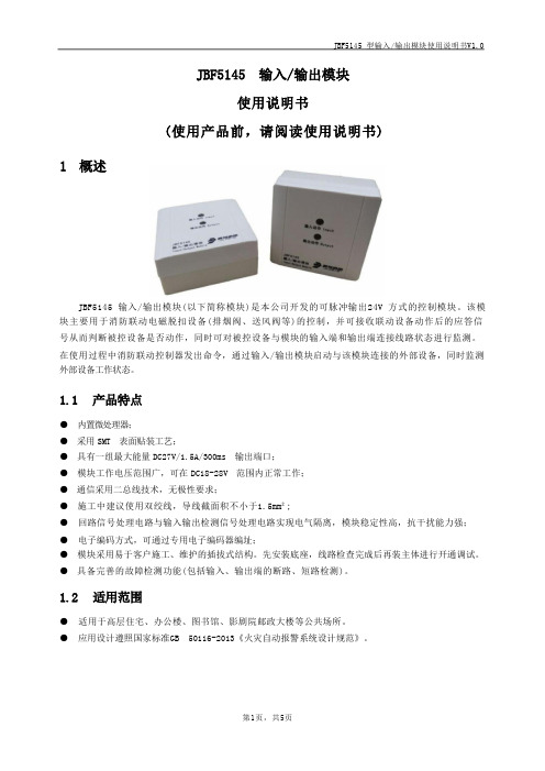
JBF5145 型输入/输出模块使用说明书V1.0
1.1 产品特点
● 内置微处理器; ● 采用 SMT 表面贴装工艺; ● 具有一组最大能量 DC27V/1.5A/300ms 输出端口; ● 模块工作电压范围广,可在 DC18-28V 范围内正常工作; ● 通信采用二总线技术,无极性要求; ● 施工中建议使用双绞线,导线截面积不小于1.5mm²; ● 回路信号处理电路与输入输出检测信号处理电路实现电气隔离,模块稳定性高,抗干扰能力强; ● 电子编码方式,可通过专用电子编码器编址; ● 模块采用易于客户施工、维护的插拔式结构。先安装底座,线路检查完成后再装主体进行开通调试。 ● 具备完善的故障检测功能(包括输入、输出端的断路、短路检测)。
向上
安装
④
④
VO+
VO- S- 5
em[ 10%
eml[ 10%
1N4007
及馈 EQU
4.2 调试方法
图 3 接线示意图
● 首先使用电子编码器对JBF5145 输入/输出模块进行编码。
● 模块安装好后操作控制器对其进行登记,然后必须在系统中手动将其设置成电池储能设备。
● 进入手动启停现场设备界面,输入要启动的模块回路及地址启动,模块输出动作指示灯变为红 色常亮,被控设备动作,模块收到被控设备的无源反馈后输入动作指示灯变为红色常亮。
5110说明书,DSE5110控制器图纸,技术资料

4. 操作面板
4.1 按键的功能说明
序号 符 号
说明
1、停车键功能
1
2、报警清除功能
3、进入功能设置键
1、 手动启动功能
2
2、 参数设置功能中的“减”功能键
3
1、 参数设置功能下的“加”功能键
7
深圳市威华特科技有限公司 DSE5110 自启动控制器
1、 自动启动功能
4
2、参数设置功能下的“确认”功能键
2. 控制器外形结构与连线
2.1 前面板布局:
仪表 翻 页按钮
常规报 警 LED 指示灯
操作及其 设置按钮
液晶 显示屏
用户自 定义指 示标志
1
深圳市威华特科技有限公司 DSE5110 自启动控制器 2.2 背面板布局:
2.3 装置尺寸:
面板开孔尺寸220mm×160mm 注意:该模块为前面板安装形式,由 4 个安装定位夹固定,在剧烈震动
互感器 变流器等级
起动信号丢失
5A 建议 1 级或更高 在信号丢失前至少保持 10V 电压并且恢复电 压为 5V 的条件下,可经受 50ms 的 0V 输入。 该功能无须内部电池即可完成
电磁兼容性
BS EN 50081-2 EMC 通用环境辐射标准(工 业)
电气安全性
BS EN 50082-2 EMC 通用抗干扰标准(工业) BS EN 60950 I.T 设备,包括商用电器设备
连接至第47脚的导线不可用于 任务其它设备的地线连接。
深圳市威华特科技有限公司 DSE5110 自启动控制器 2.5 具体电气连接说明:
通过锁定式插头插座的方式进行连接,参见背面板布局图,接线时以背
膜针脚编号为准。
针
北大青鸟消防产品综合技术说明
目录一、北大青鸟集团简介 (3)二、北大青鸟环宇消防设备简介 (3)三、关于产品新国标说明 (5)四、JB-TG-JBF-11S智能型火灾自动报警控制系统简介 (6)五、北大青鸟消防产品综合技术性能指标 (12)1、点型光电感烟火灾探测器 (12)2、点型感温火灾探测器(A2) (13)3、探测器底座 (14)4、点型感温火灾探测器(A2)-非编址型 (15)5、手动火灾报警按钮 (16)6、手动火灾报警按钮(带插孔) (17)7、编码型可燃气体探测器 (18)8、线型光束感烟火灾探测器 (19)9、消防联动输入模块 (20)10、消防联动输入输出模块 (21)11、消防联动输入模块 (22)12、JBF-171F-N总线隔离模块 (23)13、消防联动输入输出模块 (24)14、编码型声光报警器 (25)15、楼层火灾显示盘 (26)16、火灾报警控制器 (27)17、多线手动控制盘 (28)18、总线控制盘 (29)19、单路直流电源 (29)20、备电直流供电单元 (30)21、广播录放盘 (30)22、通用型功率放大器 (31)23、消防广播音箱 (31)24、多线制消防主机 (32)25、CRT火灾自动报警图文显示系统 (33)七、北大青鸟产品常用设备接线示例 (36)1、J-SAP-M-JBF-101F-N编码型手动报警按钮 (36)2.J-SAP-M-JBF-101F-N/P带插孔编码型手动报警按钮 (37)3、JBF-131F-N编码型信号输入模块 (37)4、JBF-141F-N编码型总线输出模块 (38)5、JBF-143F 总线广播模块 (41)6、JBF-151F/D 联动双切换模块 (42)7、JBF-161F编址型声光报警器 (43)八、北大青鸟消防自动报警系统联动模块与联动设备间接口说明 (44)附录1:售后服务承诺.................................................................................. 错误!未定义书签。
北大青鸟JB-QB-JBF5012说明书
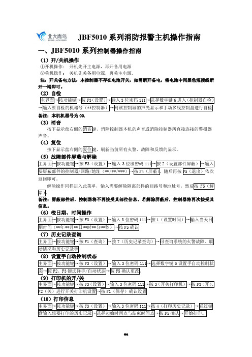
JBF5010系列消防报警主机操作指南一、JBF5010系列控制器操作指南(1)开/关机操作①开机操作:开机先开主电源,再开备用电源②关机操作:关机先关备用电源,再关主电源。
注:开关备电方法:本控制器不存在电池开关,如需断开备电,将电池中间黑色短接线断开一端即可。
(2)自检备注:本机机器号为00.(3)消音声音。
(4)复位(5)故障部件屏蔽与解除返回即可。
备注:屏蔽部件后,控制器将不再接受其部位信息。
若解除屏蔽后,控制器将再次接受其信息。
(6)校日期、时间操作(7)历史记录查询(8)设置手自动控制状态(10)打印信息(11)单点联动备注:本机机器号为00。
二、控制器报火警处理步骤(1)、当主机报火警时:当火灾报警控制器发出火灾报警时,首先应按消音键中止警报声,然后根据控制器的报警信息确认发生火警的部位,值班人员持通讯工具和灭火器迅速到现场确认是否有火灾警情,或者是否为部件误报。
①如果是报火警,首先要通过通讯工具通知消防控制室人员,通过多线盘上的自动锁把主机调为自动允许状态,启动消防相应的联动设备(如声光报警器、排烟风机、水泵、电梯、广播等),并且要组织人员使用灭火器、消防栓等灭火器材在现场进行灭火,并用广播通知人员疏散。
火势较大时务必要拨打119火警电话。
②如果是部件误报,检查误报火警部位是否灰尘过大、温度过高,确认是否是由于人为或其它因素造成误报警。
按“复位”键使控制器恢复正常状态,观察是否还会误报;如果仍然发生误报可将其屏蔽,并尽快通知安装单位进行维修。
在每次报火警现场处理好后,要将消防主机进行复位,这样火灾报警控制器所显示的火警信息才能取消。
(2)当主机报故障时:当发生故障时,首先应按“消音”键中止警报声。
然后应根据控制器的故障信息检查发生故障的部位,确认是否有故障发生;若确认有故障发生,应根据情况采取相应措施:①当报主电故障时,应确认是否发生市电停电,否则检查主电源的接线、熔断器是否发生断路。
- 1、下载文档前请自行甄别文档内容的完整性,平台不提供额外的编辑、内容补充、找答案等附加服务。
- 2、"仅部分预览"的文档,不可在线预览部分如存在完整性等问题,可反馈申请退款(可完整预览的文档不适用该条件!)。
- 3、如文档侵犯您的权益,请联系客服反馈,我们会尽快为您处理(人工客服工作时间:9:00-18:30)。
北大青鸟SF5100主机说明书
一、火警
控制器发出消防车火灾报警声时,面板火警灯亮。
按下“消音”键,观察报火警地址并派人查看。
1.如果是探测器误报或手动报警按钮被人为按下,排除后将控制器复位即可。
复位操作:按下“复位”键,在输入密码“111”主机恢复正常运行。
2.如果是真火情,在人为无法扑救的情况下,将控制专线盘的“手动”与“自动”都打在“允许”状态上,并拨打电话119通知消防队。
3.观察控制主机是否启动消防水泵,如没有请按下消防主机处的消防水泵按钮启动消防水泵。
二、消防广播
当接到疏散指令后,开启应急疏散广播疏散人员。
操作如下:
关闭背景音乐音源,按下“应急广播”按钮——“应急广播”红灯亮,打开话筒,播放应急疏散广播。
三、故障
控制器发出鸣叫,面板故障灯亮。
按下“消音”键,观察报故障地址并派人查看。
将故障部件拆下,清理接触点再装回。
如果故障仍不排除,
将故障通知维保单位。
四、屏蔽如维保单位不能及时到位,需将外部设备屏蔽。
按F2“设置”键输入密码“111”进入“设置选项”,选择“2”项进入故障部件屏蔽操作,输入故障部件的回路号及地址号,按下F3屏蔽键,故障部件被屏蔽不再报故障,面板隔离灯亮。