中控门禁FR1200安装指南 V1.1
门禁系统安装方法图解
门禁系统安装⽅法图解 门禁系统是现代商业⼤厦、⼩区、学校、企业等使⽤较多的安全保安系统。
门禁系统是先洗个现代化安全管理系统,集微机⾃动识别技术和现代安全管理措施为⼀体。
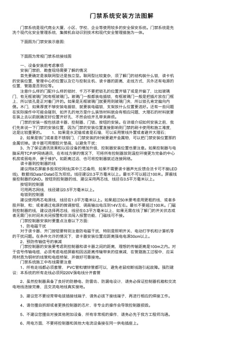
下⾯图为门禁安装⽰意图: 下⾯图为常规门禁系统接线图 ⼀、设备安装前考虑事项 安装门禁前,勘查现场需要了解的情况 ⾸先要确定是装联⽹型还是独⽴型。
联⽹型⽐较复杂,须了解门的结构装什么锁,读卡机的安装位置,管理中⼼的位置以及它与控制主机、读卡器的距离,⾛线⽅式,另外还有电源的位置,管路是否到位等。
注意什么样的门配什么样的锁时,千万不要把锁孔的位置开错了或是开偏了,⽐如玻璃门,有⽆框玻璃门和有框玻璃门。
玻璃门⼀般都装电插锁,有框玻璃门⼀般是把插⽚放在门框上,所以锁孔是正对着门开的。
如果是⽆框玻璃门就要⽤到玻璃门夹,所以锁孔肯定偏向内侧。
⽊门,如果厚度不够安装电插锁,就要装电磁锁,⽀架放什么位置要选好。
还有⼀些问题在实际操作中可能会碰到,如开孔的地⽅是什么装饰材料就会有相应问题,⼤理⽯的材料就要在装上去以前就确定好位置开好孔,不然会给开孔带来⿇烦。
门禁的安装⼀般包括读卡器、控制器、门锁、按钮的安装。
在详细介绍如何安装之前,我们先来说⼀下门禁的安装位置,因为门禁的安装位置直接影响到门禁的刷卡使⽤和施⼯难度,这是⽐较重要的。
1、如果是⽔泥墙或者是⽯墙,可以采⽤管线外置或者避开⼤理⽯; 2、如果是铁门或者是不锈钢门,门禁安装的时候要避开⾦属物,可以把门禁安装位置那的⾦属切掉。
读卡器可⽤塑胶⽚垫⾼,以避免⼲扰; 3、为了保证通讯效果和以后设备的增加升级,控制器安装位置也要注意。
如果控制器与电脑采⽤TCP/IP⽹络通讯,在布线⽅便的情况下,可将所有控制器放到温控环境更为完备的中⼼机房或弱电井,便于维护。
如距离过远,也可将控制器就近连接⽹络。
读卡器到控制器的线 建议⽤8芯屏蔽多股双绞⽹线(其中三芯备⽤,如果不需要读卡器声光反馈合法卡可不接LED 线),数据线Data1Data0互为双绞。
门禁软件安装指导手册

门禁软件安装步骤一、概述本门禁控制系统是一套集成的基于个人的安全系统,具有一系列的优点和丰富的功能。
本门禁控制系统能从多个位置控制和报告持卡者的出入、报警以及其他系统活动。
本手册为您提供了详细的软件安装步骤指导二、安装要求本门禁控制系统可以运行于 Windows 2000、Windows XP Professional 或 Windows NT操作系统上,可以为单用户或多用户系统服务。
三、软件安装1.服务器端软件安装步骤:“Install the Software ‐ Server”运行Autorun.exe后会出现安装窗口,为安装服务器端软件。
点击红框部分,如图:如果已经安装有数据库软件,会弹出如下窗口:在红框部分填入数据库管理员“sa”的密码,如果是自行安装的数据库,那么需要填入安装数据库时设置的“sa”密码(不建议把“sa”的密码设置为“空”);如果安装的是软件自带的MSDE数据库,那么“sa”的默认密码为“secadmin1”,如下图:填入密码后点击“Next”,弹出如下窗口:直接点击“Next”,弹出如下窗口:选择“I Agree”如下图:点击“Next”后弹出如下窗口:选择要安装的路径,如下图:点击“Browse…”可以选择要安装的目录,如上图中的红框部分,如使用默认目录可直接点击“Next”。
点击“Next”后弹出如下窗口:在窗口中“SP Name”和“Cim Name”默认的为计算机名称,为方便以后的配置,建议修改名称。
图中红框部位为修改后的名称,“建议修改为SP32和CIM1”选择“Use hosts file for IP Resolution”复选框后,“SP IP Address”和“Cim IP Address”变成可填,在这里填入服务器的IP地址。
如下图:点击“Next”后弹出如下窗口:这里为数据库的名称,不用修改。
点击“Next”后弹出如下窗口:点击“Next”后弹出如下窗口:开始安装软件程序。
ZKTECO FR1200 User Manual V1.0.1

ZKTeco FR1200 User ManualVersion: 1.0.1Date:Dec.2011Introduction:This document mainly introduces the user’s operation of ZKTeco FR1200. About the device installation, please refer to the Installation Guide.Table of ContentsTable of Contents1. Using Instruction............................................................................ 1 1.1 Finger Placement.................................................................. 1 1.2 Instruction for Card Using.................................................... 2 1.3 Precautions............................................................................ 2 2. Device Introduction........................................................................ 3 3. Device Operations .......................................................................... 6 4 Appendix........................................................................................ 11 4.1 List of Parameters............................................................... 11 4.2 Statement on Human Rights and Privacy........................... 12 4.3 EnvironmentFriendly Use Description.............................. 14 ing Instruction1. Using Instruction1.1 Finger PlacementEnroll fingerprint by pressing index finger, middle finger or ring finger (thumb and little finger are clumsy).1. Proper press:2. Improper press:Make finger center pressed on thesensor window.Slant Too lowUpright Too leanPlease adopt the correct way to place the finger to avoid improper operation led to the identification performance degradation.ZKTeco FR1200 User Manual V1.0.11.2 Instruction for Card UsingIntegrated with a noncontact RF card reader module, this reader supports the ID cards and Mifare cards (Optional and only used as ID cards). By offering multiple verification modes such as FP, card, FP plus card, FP or card verification, this reader can accommodate to diversified user needs.Swipe your card across the sensor area following the light and beep prompts and remove your card after the reader has sensed it. For the card sensor area, please refer to2 Device Introduction.1.3 PrecautionsProtect the reader from exposure to direct sunlight or strong beam, for the strong sunlight greatly affects the fingerprint collection and leads to fingerprint verification failure.It is recommended to use the reader under a temperature of 0–50°C so as to achieve the optimal performance. In the event of exposure of the reader to the outdoors for long periods of time, it is recommended to adopt sunshade and heat dissipation facilities because excessively high or low temperature may slow down the reader operation and result in high false rejection rate (FRR) and false acceptance rate (FAR).When installing the reader, please connect the power cable after all the other wiring. If the reader does not operate properly, be sure to shut down the power supply before performing necessary inspection. Be aware that any liveline working may cause damage to the reader, and that damage is beyond the scope of our normal warranty.For matters that are not covered in this document, please refer to related materials including the Installation Guide, FP Reader Software User Manual.2.Device IntroductionLED IndicatorFingerprint SensorCard Sensor Area2. Device IntroductionFR1200, a fingerprint reader with RS485 communication interface works with biometric access controllers and fingerprint standalone access control. It offers the function of capturing and transferring fingerprint samples to access control panel inside to match. With its IP65 rated rugged structure.This reader operation is simple and flexible. The light and beep prompts will guide you through all the operations without screen display or keyboard. Featuring a compact and simple design, this reader is a new concept of inBIO fingerprint reader.Product Appearance:Front view:² LED indicator: The LED indicator is used to display reader operation resultsand exceptional statuses which are defined as follows:ZKTeco FR1200 User Manual V1.0.1Dip SwitchWiring TerminalReset ButtonOperation succeeds: The green indicator is solid on for one second, at the same time the speaker play one long beep.Operation failed: The red indicator is solid on for one second, at the same time the speaker play two short beep.Verification state: The green LED blinks once every two second, the beeper with no sound.² Card Sensor Area: Refers to the area in the red dashedline as shown in thefigure above.² Fingerprint Sensor:Used to enroll and match fingerprints.Bottom view:² Reset Button:Used to restart the reader.Back view:Dip Switch: 14 switches are used to set the RS485 communication address (device ID). Number 5 switch is idle. And the number 6 switch is used to set the terminal2.Device Introduction resistance state.Wiring Terminal:For connection terminals.ZKTeco FR1200 User Manual V1.0.13. Device OperationsAfter the reader is powered on, the reader can not identify the fingerprint or card. In other words, the reader can not receive data or send data without access control panel connection.Only when the reader connected with the access control panel that the reader can prompt if the card or fingerprint is enrolled or not, and verify the user according to the returning result of background access control panel.User verification operations:1. When the reader connected with the access control panel, it is in verification state, the beep with no sound, and the green LED blink once every two second to prompt verification.2. Start user verification. The reader supports four verifications modes: only fingerprint, only card, fingerprint plus card, fingerprint or card verification. The process include press fingerprint first or swipe card first, the operation are as the follows:Press fingerprint first:(1) Press your finger on the fingerprint sensor in a proper way. The device beeps once, and then the LED off, switch to the background verification.(2) The access control panel determines whether the control order is timeout. If it is timeout, the device beeps 3 sounds and the red LED solid on. Otherwise, it will get the system verification modes setting.Only fingerprint/card or fingerprint verification: Send the fingerprint template to the access control panel, and wait for the result. If it is waiting time out, beep 3 sounds and the red LED solid on. If the reader get the verification result in the3.Device Operationssetting time, 2 beep and red LED solid on for verification failed, 1 beep and green LED solid on for verification succeed.Card plus fingerprint verification: Determine if there is the card data. If you swipe card near to the card reader, then send the fingerprint template and card data to the access control panel, and wait for the result. If it is waiting time out, beep 3 sounds and the red LED solid on. If the reader get the verification result in the setting time, 2 beep and red LED solid on for verification failed, 1 beep and green LED solid on for verification succeed.Only card verification: No sending of the data to access control panel, the device beeps 2 sounds, and red LED solid on.ZKTeco FR1200 User Manual V1.0.1The verification operations are as follows: Reader StartGetting controlorder timeout?Only FPverification ?FP or cardverification ?FP and card verification ?Send card numberand FP template toaccess control panelPrompt: 1beep, green LED on Verificationresult timeout ?NY N NGet FP template, 1beep,light off,switch to 485Only card verification ? Get card numberalready?? Y Y Y Send FP template toaccess control panel Pass theverification?Prompt: 2 beeps, red LED on Reader stopPrompt: 3 beeps,green LED on NNYNNYY Y3.Device OperationsSwipe card first:(1) Swipe your card on the card reader in a proper way. The device beeps once, and then the LED off, switch to the background verification.(2) The access control panel determines whether the control order is timeout. If it is timeout, the device beeps 3 sounds and the red LED solid on. Otherwise, get the system verification modes setting.Only card/card or fingerprint verification: Send the card data to the access control panel, and wait for the result. If it is waiting time out, beep 3 sounds and the red LED solid on. If the reader get the verification result in the setting time, 2 beep and red LED solid on for verification failed, 1 beep and green LED solid on for verification succeed.Card plus fingerprint verification: Determine if there is the fingerprint data. If it is waiting time out, beep 3 sounds and the red LED solid on. Otherwise, it will follow the card plus fingerprint verification as press fingerprint first.Only fingerprint verification: No sending of the data to access control panel, the device beeps 2 sounds, and red LED solid on.? Note: For the verification mode setting, please refer to the FP reader software user manual or relevant software user manual.ZKTeco FR1200 User Manual V1.0.1The verification operations are as follows:Reader StartGetting control order timeout?Only card verification ?FP or card verification ?Only card verification ?Send no data to access control panel, switch to main mission, waiting for FP and follow the verification process of press FP firstPrompt:1beep, green LED on Verification result timeout ?NYNGet card,1beep, light off, switch to485FP and card verification ?YYSend card number to access controlPass the verification?Prompt:2beeps, red LED onReader StopPrompt:3beeps, green LED on NNYNNYYYN4Appendix4 Appendix4.1 List of ParametersThe following table lists the basic functional parameters of the reader.Item Note Power Supply DC12V/3AExternal Function EXT 485 for access control panel connection Verification mode. ID (Mifare) card, fingerprintCommunications RS485Speaker Beep promptLED Bicolor indication (red/green)ZKTeco FR1200 User Manual V1.0.14.2 Statement on Human Rights and PrivacyDear Customers:Thank you for choosing the multibiometric products designed and manufactured by us. As a worldrenowned provider of biometric technologies and services, we pay much attention to the compliance with the laws related to human rights and privacy in every country while constantly performing research and development.We hereby make the following statements:1. All of our fingerprint recognition readers for civil use only collect the characteristic points of fingerprints instead of the fingerprint images, and therefore no privacy issues are involved.2. The characteristic points of fingerprints collected by our products cannot be used to restore the original fingerprint images, and therefore no privacy issues are involved.3. We, as the equipment provider, shall not be held legally accountable, directly or indirectly, for any consequences arising due to the use of our products.4. For any dispute involving the human rights or privacy when using our products, please contact your employer directly.Our fingerprint products or development tools for police use support the collection of the original fingerprint images. As for whether such a type of fingerprint collection constitutes an infringement of your privacy, please contact the government or the final equipment provider. We, as the original equipment manufacturer, shall not be held legally accountable for any infringement arising thereof.Note: The law of the People’s Republic of China has the following regulations regarding the personal freedom:1. Unlawful arrest, detention or search of citizens of the People's Republic of China is prohibited; infringement of individual privacy is prohibited.4Appendix2. The personal dignity of citizens of the People's Republic of China is inviolable.3. The home of citizens of the People's Republic of China is inviolable.4. The freedom and privacy of correspondence of citizens of the People's Republic of China are protected by law.At last we stress once again that biometrics, as an advanced recognition technology, will be applied in a lot of sectors including ecommerce, banking, insurance and legal affairs. Every year people around the globe suffer from great loss due to the insecurity of passwords. The fingerprint recognition actually provides adequate protection for your identity under a high security environment.ZKTeco FR1200 User Manual V1.0.14.3 EnvironmentFriendly Use DescriptionThe Environment Friendly Use Period (EFUP) marked on this productrefers to the safety period of time in which the product is used under theconditions specified in the product instructions without leakage ofnoxious and harmful substances.The EFUP of this product does not cover the consumable parts that needto be replaced on a regular basis such as batteries and so on. The EFUP ofbatteries is 5 years.Names and Concentration of Toxic and Hazardous Substances or ElementsToxic and Hazardous Substances or ElementsParts NamePb Hg Cd Cr6+ PBB PBDE Chip resistor´ ¡ ¡ ¡ ¡ ¡ Chip capacitor × ¡ ¡ ¡ ¡ ¡ Chip inductor × ¡ ¡ ¡ ¡ ¡ Chip diode × ¡ ¡ ¡ ¡ ¡ ESD components × ¡ ¡ ¡ ¡ ¡ Buzzer × ¡ ¡ ¡ ¡ ¡ Adapter × ¡ ¡ ¡ ¡ ¡ Screws ¡ ¡ ¡ × ¡ ¡ ¡: Indicates that this toxic or hazardous substance contained in all of the homogeneous materials for this part is below the limit requirement in SJ/T113632006.×: Indicates that this toxic or hazardous substance contained in at least one of the homogeneous materials for this part is above the limit requirement in SJ/T113632006.Note: 80% of the parts in this product are manufactured with nonhazardous environmentfriendly materials. The hazardous substances or elements contained cannot be replaced with environmentfriendly materials at present due to technical or economical constraints.。
2018年门禁安装步骤-word范文模板 (5页)

本文部分内容来自网络整理,本司不为其真实性负责,如有异议或侵权请及时联系,本司将立即删除!== 本文为word格式,下载后可方便编辑和修改! ==门禁安装步骤篇一:门禁系统的安装方法及措施门禁系统的安装方法及措施1、门禁系统施工方法及措施1.1、设备安装(1)前端设备 A、进门处安装读卡器。
在读卡器感应范围内,切勿靠近或接触高频或强磁场(如重载马达、监视器等),并需配合控制箱的接地方式。
B、出门处安装出门按钮。
C、电磁锁安装在门和门框的上沿。
D、为保证安全性和美观性,控制器和电源箱可采用现场安装或安装于弱电井内。
现场安装控制器的优点在于节约线材的使用,控制器安装于弱电井内便于系统日后的维护和系统的安全,也可将控制器箱安装在读卡器上方,靠近电磁锁处。
具体情况可根据客户选择安装方式。
(2)中控室设备A、控制主机和键盘安装在立面墙上或置于工作台上。
B、报警装置放置在报警效果较好的位置。
C、由于门禁系统的特殊性,要求对该系统供电良好,建议采用 UPS电源,对门禁系统集中供电。
1.2、设备调试(1)系统安装完成后,先把一路门禁读卡器信号接入主机,然后单独检测该路门禁读卡器情况,有无漏报、误报情况发生。
这一路检测没问题后在接入另一路,如此这样,把每一路都单独检测一遍,确认无误后再把所有线路接齐。
(2)管理人员可以根据使用人员的权限分别授权,如部分人员可以在任意时间进出任意的地点,普通人员只能凭授权卡在授权时间内进出授权范围。
当所有门禁点的正常开启和非法开启时,查看控制中心电脑是否有纪录。
(3)尝试中心电脑因故障或其它原因不能和控制器连接,控制器是否可以独立纪录所控制门点的相关信息,当中心电脑连接后,所有信息是否可以自动上传,是否可以保证信息纪录的完整性。
(4)做好调试记录。
(5)最后填写竣工报告。
1.3、管线安装(1)安装工程布线应符合国家规定“电气装置工程施工及验收规范”及国家颁发的有关规范及规定。
在管内或线槽内的穿线,应在建筑抹灰及地面工程结束后进行。
门禁系统安装说明书

Assembly instructionsSFT 1223SFT 10237084823-03ContentSafety instructions and warnings (2)Appliance dimensions (2)Cable lengths (3)Requirements for assembly (4)Requirements for the place of installation (4)Minimum distance to ceiling (4)Requirements for the electrical connection (4)Requirements for a remote data transmission connection ..5Bus connection (5)Addressing (5)Operation (LSC version only) (5)Example of networking on 2 levels: (5)Scope of delivery (6)Standard (per appliance) (6)Accessories (depending on configuration) (7)T ransport and unpacking (7)Moving the appliances to the place of installation (7)Possible configurations (8)Installing an individual appliance (8)Installing appliances in a row (9)Installing the appliances in a block or in island form (10)Installation and connection (10)Affixing shaped foam tape (10)Fitting the cables (11)External alarm (floating alarm output) (13)Outline height adjustment (13)Final height adjustment (16)Installing the connecting plates (17)Installing the handle (19)Installing the defrost water collection tray (20)Connecting appliances (24)Assigning addresses to the appliances (24)Commissioning the appliances (25)Checks (25)T echnical data (26)Safety instructions and warnings• If there is obvious transport damage on the appliance after it has been unpacked, contact the supplier. Do not switch on the appliance.• Do not allow naked flames or ignition sources to enter the appliance. When transporting and cleaning the appliance, ensure that the refrigerant circuit is not damaged. In the event of damage, make sure that there are no ignition sources nearby and keep the room well ventilated.• Do not place any objects on the appliance.• The appliance must always be secured with 4 bolts.• The minimum appliance height must been no less than 2245 mm as shown in the table on page 3.Appliance dimensionsA [mm]B [mm]C [mm]D [mm] SFT 1223250012837091224 SFT 10232100128370912242ENCable lengths[mm]A45B812-1062C963-1213D2245-2495E47F760G7873Requirements for assemblyThe assembly must comply with the applicable regulations, standards, directives and laws where they apply to the subject of the contract.Work on the electrical system (electrical connection, cable duct or sockets) may only be carried out by a qualified electrician.NoteT o avoid the assembly work being delayed or even stopped, installation of the appliances should be carefully planned in advance. It must be ensured that all the requirements are satisfied.Requirements for the place of installation Ensure that the place of installation for assembling the appliances is suitable and properly prepared.–Any existing old appliances must be removed and disposed of in an environmentally friendly manner.–The place of installation must be free of dirt and moisture.–The evenness of the floor surface must comply with the usual limit values for evenness deviations set out in DIN 18202.–The ambient temperature must correspond to the climate rating. The climate rating applicable to your appliance is shown in the operating instructions.Requirements for the electrical connection–We recommend that separate circuits are installed for the lighting and chest refrigeration units. The sockets must be clearly distinguishable.–T wo sockets must be prepared for each appliance for these two circuits. The sockets must be permanently fixed and clearly labelled.–Each appliance must be protected by its own fuse.45ENOperation (LSC version only)Digital |/O Pin-Belegung 10polAlarmkontakt: 1N 2COM 6NC O Eingang_ 4/5 Licht ein 9/10 DI 2 optionalMODBUS RTU LSCPin-Belegung RJ-45: 2/7/8 Data -3/6 GND 1/4/5 Data +/lsc–The adjustment range of the address in menu A has beenextended to 1-247. –An additional baud rate/parity setting menu point "bd" hasbeen included: –Menu bd step 1: The set baud rate is displayed in [Bit/s * 10]and can be adjusted using the cursor keys. The two leading and the two following numbers in the baud rate flash alternately:09|60 = 9600 baud, 19|20 = 19200 baud, 38|40 = 38400 baud, 56|00 = 56000 baud. –The parity is set after confirmation by pressing the SET key.Meaning:E1 = Even parity + 1 stop bit, n2 = No parity + 2 stop bits, o1 = Oddn1 = No parity + 1 stop bit –The setting is saved by pressing the SET key. A shortacknowledgement tone means that nothing has beenchanged. A long acknowledgement tone indicates that the interface parameters have been changed.Requirements for a remote data transmission connection– A connection from the appliance blocks to the gatewaylocation must be established on site using suitable sockets and cables (CAT5 or higher) with a bus topology.Bus connectionUp to 120 appliances with CAN and 247 with MOD bus can be networked and integrated into the in-house system using one or more coupling modules.NoteThe alarm priority with CAN connectivity is limited as standard to a maximum of 2 when the appliance is delivered. This means that the forwarding of the alarm is restricted when the shop is closed. The setting can be changed if necessary by the gateway manufacturer. The list of alarm scenarios is included in the service documentation.AddressingFree addresses from the in-house system must be used toaddress the bus with one- to three-figure numbers (1-999) being allocated for this purpose.The addresses are entered individually on each appliance, see “Assigning addresses to the appliances”, page 24.Each address may only be used once within the bus.Depending on the system environment, we recommend that you–If a repeater is used, the termination must be enabled.678Lifting the appliances off the palletAt least two people are required for this.Lift the appliances off the pallets using suitable equipment and carefully lower them into position.Weight [kg]SFT 1223430SFT 1023345Possible configurationsNoteThe “Requirements for the place of installation”, page 4 and the “Requirements for the electrical connection”, page 4, must be complied with for all configurations.If the appliances are networked, the “Requirements for a remote data transmission connection”, page 5, must also be complied with.Installing an individual applianceEvery model can be installed individually.1. “Fitting the cables”, page 112. “Outline height adjustment”, page 133. Positioning the applianceNoteA maximum support thickness of 1 mm may be used underthe adjustable feet.4. “Final height adjustment”, page 165. “Installing the handle”, page 196. “Installing the defrost water collection tray”, page 207. “Connecting appliances”, page 248. “Commissioning the appliances”, page 259ENInstalling appliances in a row1. “Affixing shaped foam tape”, page 102. “Fitting the cables”, page 113. “Outline height adjustment”, page 134. Positioning the applianceNoticeWhen pushing the appliances, it is vital that you ensure that no cables are jammed or damaged.NoteA maximum support thickness of 1 mm may be used underthe adjustable feet.5. “Final height adjustment”, page 166. “Installing the connecting plates”, page 177. “Installing the handle”, page 198. “Installing the defrost water collection tray”, page 209. “Connecting appliances”, page 2410. “Assigning addresses to the appliances”, page 2411. “Commissioning the appliances”, page 2510Installing the appliances in a block or in island form1. “Affixing shaped foam tape”, page 102. “Fitting the cables”, page 113. “Outline height adjustment”, page 134. Positioning the applianceNoticeWhen pushing the appliances, it is vital that you ensure that no cables are jammed or damaged.Note6. “Installing the connecting plates”, page 177. “Installing the handle”, page 198. “Installing the defrost water collection tray”, page 209. “Connecting appliances”, page 2410. “Assigning addresses to the appliances”, page 2411. “Commissioning the appliances”, page 25Installation and connectionAffixing shaped foam tapeAffix the shaped foam tape to the top and front sides of the appliances to keep the contact areas of appliances in rows or blocks free of dirt. This allows the appliances to be placed next to each other without gaps in between and also compensates for minor unevenness.NoteDo not affix shaped foam tape to the outer side panels of the first and last appliance in the row.ENFitting the cablesNoticeThe cables must be routed so that each appliance, including those in rows or blocks, can be pulled out individually without any problems for repair or service purposes.Cables must not be jammed or damaged by this. Use any available cable suspension points.1.2. Connect the network cable.NoteThe ports (input/output) may be freely selected. The plugs must engage with an audible click.First applianceAdditional appliances–Connect one plug of the network cable (A).–Connect the other plug of the network cable (A) to the–T o connect additional appliances, connect the plug ofNoteThe empty port on the last appliance in a configuration is used for connection to the coupling module and then to the in-house LAN.Both bus ports must therefore be occupied on every appliance.3. Connect the light cable plug.See also “External alarm (floating alarm output)”, page 13.NoteThis plug does not need to be connected if the lighting is 4.5.EN External alarm (floating alarm output)It is possible to connect the appliance to an external alarmdevice.Crimp contacts can be added to the light cable for this purpose.NoteIf there is no light cable (e.g. if the lighting is controlled via thenetwork), a plug with crimp contacts is available separately.The contacts (NC, NO and COM) can be used to connect theappliance to an optical or acoustic alarm device.The connector is designed for a maximum of 230 V AC/10 Aor 24 V DC/5 A from a SELV (safety extra-low voltage) source(minimum current 150 mA).NoticeWhen supplying mains voltage to the floating alarm contact, the1NO6NC2COM7free3free8free4Light IN (bn)9DIGITAL IN 230 V AC5Light IN (bu)10DIGITAL IN (neutral)NC operating lightConnection for a control lamp to indicate that the appliance is innormal mode.COM external power supply unitMaximum 230 V AC/10 A or 24 V DC/5 AMinimum current 150 mANO alarm outputConnection for a visual warning light or an acoustic alarm signal.Outline height adjustment1. Remove screwsImportantBefore removing the screws, ensure that the appliance issecured by suitable lifting gear above the centre pallet.EN5. Insert the pinsImportant!The appliance must always be secured with 4 pins.Final height adjustmentImportantOn delivery, the appliance is in a "neutral state". T o allow the height to be adjusted, the screws must be inserted into the long slot.Never remove all the screws at the same time.1. Screw types2. Undo the retaining screwsImportant!Never remove the screws. Danger of tipping.EN Installing the connecting platesB) Block configuration [torque 4-5 Nm]C) Row configuration wall mounting3. Add around 125 ml of water so that the tube outlet isInstalling the defrost water collection tray216. Variant 222EN 2324Assigning addresses to the appliancesThe control menu will appear :Menu A for entering the address will appear:Menu H for entering the hundreds figure will appear; the relevant number will flash: –Select the required value using.Connecting appliances If separate circuits are used for lighting and cooling, the relevant sockets must be clearly labelled.1. Plug the mains plug of the power connection cable intothe appropriate socket.If the mains plug of an appliance isaccidentally placed into a lighting socket, when the circuit for the lighting is switched off (e.g. at night), the cooling function will no longer work and the food inside the appliance will be spoiled.EN Menu C for entering the tens figure will appear; the relevantnumber will flash:–Select the required value using .–Press Set briefly to confirm.Menu E for entering the units figure will appear; the relevantnumber will flash:–Select the required value using .The idle screen will appear:NoteWe recommend that the address of each appliance is notedor documented (e.g. an adhesive label on the rear of theappliance) to speed things up for service work.Commissioning the appliancesChecks–T est the lighting connections (if the circuits are separate):Remove the light fuses – all the appliances must be unlit. Ifthis is not the case, the plugs on the appliances which are lithave been inserted in the wrong sockets, see “Connectingappliances”, page 24.–Check the appliances for correct functioning and correcttemperature setting:T est the various appliances to ensure that they functionperfectly.If any defects which cannot be rectified are found, pleasenotify our customer service department.–Check the addresses:Check the settings of the appliances using the test tool.NoteRemove the dirt caused by the installation, following theinformation in the section entitled "Cleaning" in the operatinginstructions.This completes the installation work.See the operating instructions of the relevantappliance for further information about operation.2526Technical data2.50 m2.1 mOperating mode FreezingFreezingDescriptionSFT 1223SFT 1023Overall electrical data (including LED lighting)Rated voltage Frequency220-240 V 50 / 60Hz 220-240 V 50 / 60Hz Rated current 5 A5 ACompressor system inverter (frequency converter)Y es Y es Fuse on each applianceRCBO 10 to 16 A Characteristic B, CRCBO 10 to 16 A Characteristic B, CLength of mains cable 2.50 m2.50 mInterface (standard)CAN bus CAN bus Interface (alternative)MODBUS MODBUS Electrical data for LED lightingPower consumption49 W40 WEN 27*708482303* Liebherr Hausgeräte Lienz GmbHDr.-Hans-Liebherr-Strasse 1A-9900 LienzÖsterreich。
门禁的安装方法

门禁的安装方法
随着社会的发展,安防技术的不断进步,门禁的安装已成为人们安全防范的不可缺少的一环。
为了保证安全,确保安装的质量,确保其安装后的正常使用,门禁安装时应注意一些方面。
首先,有关技术方面的支持,应当仔细研究相关的技术资料,深入了解门禁的各项技术性能,明确各项要求,确定出合理的安装方案,从而确保安装顺利进行,并能够达到预期的效果。
其次,门禁安装时,应遵循安装图纸设计,实施质量化管理,根据安装图纸和实施质量化管理,安装时应仔细比对、检查和核实,保证安装结构的正确,以便达到预期的效果。
第三,安装过程中有关安装,组装,拆装等工作应交由经验丰富的人员来完成,以确保工作质量,防止意外发生,避免人为影响系统的正常运行。
第四,安装完成后,应检查门禁的连接线路,检查其是否符合安装要求,确保各部件的完整性和工作正常,并进行系统测试,以确认系统的正确性。
最后,在制定安装方案中,应考虑以下几点:一是安装完成后,安装人员应给使用者进行系统操作培训,以让使用者熟悉系统的操作,使用起来更加方便;二是在安装过程中应当注意安全因素,确保安装和操作的安全可靠。
安装完成后应对所有安装点进行检查,确保没有失效点,从而确保门禁的正常使用。
门禁的安装是一项技术性的工作,必须仔细考虑,详细论述,确
保在安装时准确无误。
安装完成后,应当及时进行检查和维护,以防止发生意外,保证后续使用的正常性。
总之,门禁的安装要注意细节,确保安装质量,这样才能确保安全,提高工作效率。
中控指纹门禁使用手册

指纹门禁软件使用手册序言F7 的诞生,标志着中控指纹机进入专业的门禁领域,因此,我们开发该软件以方便门禁的管理。
该版本为第一版,主要的功能有以下几点:一、可以实现多机联网,实时监控指纹机不管是以太网连接还是485 连接都可以添加到管理软件中来管理,把所有的指纹机都加入之后,点击“开始监控”,便开始从头至尾的轮询监控。
二、实时记录下载可以实时的下载每台指纹机上的指纹记录,这些记录下载后会自动存储到数据库中,如果有中控考勤软件,把考勤软件的数据库路径指定为该数据库的路径,这样就可以随时查看考勤情况。
三、查询记录并以多种格式导出记录当指纹记录较多时可以查询记录,在查询中,定义了多条件查询功能,比如说按指纹机号,还有时间段,部门等。
另外,还可以把记录以多种格式导出。
四、上传门禁设置上传基本门禁设置和用户门禁设置五、部门管理六、用户管理主要有,下载用户及指纹,修改用户信息及权限,给用户增加密码,还可以用U are U 新增用户,最后上传用户。
七、远程开门八、同步时间九、升级指纹机固件十、初始化指纹机十一、系统管理,详述请查说明文档。
使用的流程可分以下几个步骤:一、硬件的连接这是第一步,把所有指纹机和电脑连起来,在距离不超过100 米的情况下建议用以太网连接,超过100 米的用485 线连接。
二、用户管理这个环节主要是给每台指纹机登记或上传用户,如果每台指纹机的用户都一样,建议先在一台指纹机上登记所有的用户,然后下载到电脑,在软件中对用户作完维护后,再分别上传到每台指纹机上。
三、门禁管理作为门禁,我们可以把所有的用户初始为禁止用户,只有给用户分配权限后,用户才会在其有效的时段内成为合法用户,因此,我们在上传完用户后,接下来就要上传门禁设置。
本软件由中控软件研发部开发,由于是首发版本,加之时间仓促,所以有许多不成熟之处,欢迎广大用户指出宝贵的建议,我们将非常感谢你对我们的支持,并会根据您的建议改进软件。
硬件连接图交换机U are U 4000485转接头管理软件使用流程图已登记用户的指纹机时间段下载用户U are U增加新用户基本门禁设置组员工维护上传门禁设置开锁组合上传用户用户门禁设置用户权限分配未登记用户的指纹机目录1 软件的安装及授权许可 (7)1.1 软件的安装 (7)1.2 授权许可 (7)2 设备管理 (8)2.1 添加指纹机 (8)2.1.1 串口/RS485 (8)2.1.2 以太网................................................................. 9 2.2 读取设置 (10)2.3 设置信息 (10)2.4 初始化设备 (11)3 系统设置 (11)3.1 程序开始时启用自动监控 (11)3.2 指定时间段启动监控 (11)3.3 同步考勤机时间 (11)3.4 默认设备轮询周期数和连接失败重试次数 (11)3.5 保留设备记录数 (12)3.6 功能配置 (12)3.7 自动启动 (12)3.8 设置数据库连接 (12)4 部门管理 (13)5 用户管理 (14)5.1 U are U 采集指纹 (14)5.2 从电脑到指纹机 (15)5.3 从指纹机到电脑 (16)6 门禁设置 (17)6.1 时间段 (18)6.2 组 (18)6.3 开锁组合 (19)6.4 用户权限 (20)7 查询 (22)8 系统管理 (23)8.1 操作员管理 (23)8.2 系统操作日志 (24)8.3 备份数据库 (24)8.4 恢复备份 (25)8.5 数据库压缩与修复 (25)8.6 清除过期数据 (25)8.7 初始化系统 (25)8.8 设置数据库密码 (26)9 有关门禁软件的快捷操作 (26)9.1 快捷按钮 (26)9.1.1 远程开门 (26)9.1.2 上传设置 (26)9.1.3 开始监控 (27)9.2 右键快捷功能 (27)9.2.1 禁用 (27)9.2.2 下载记录 (27)9.2.3 清除记录 (27)9.2.4 升级固件 (27)9.2.5 同步时间 (27)1 软件的安装及授权许可1.1 软件的安装点击中控门禁管理软件安装包,会弹出安装路径的对话框,根据自己的习惯可更改安装路径,如下图:指定安装路径后,点击“安装”即可完成本软件的安装。
中控门禁F18安装指南V1.1

3. TCP/IP通讯方式
端子定义见右表: 两种连接方式如下: (1) 设备与电脑通过交叉网线直接连接。
端子名称 RJ45-1 RJ45-2 RJ45-3 RJ45-6
线序 TX+ TXRX+ RX-
颜色 白橙 橙 白绿 绿
1. 设备到门禁控制器或读卡器的距离建议不超过90米(如需传输距离更长或使用环境中有干扰时, 请使用Wiegand信号延长器)。 2. 不论设备是否与门禁控制器或读卡器共用电源,都必须确保设备与门禁控制器或读卡器共地,以 保证Wiegand信号稳定。
+
DC12V
FR 107
+
+
-
11
+
-
FR 107
+12V GND BELLBELL+ SEN GND BUT NO1 COM1 NC1 NO2 COM2
设备与锁不共用电源情况: 1)ULOCK=12V 且 I-ILOCK≤1A; 2)ULOCK≠12V; 3)锁与设备之间距离>10 米时。
-
五、连接电源
F18 安装指南
一、安装设备
版本:V1.1
日期:2011年11月
三、连接门锁
1. 设备与锁共用电源
+ +
!
警告:请勿带电接线!
布线孔
+12V GND BELLBELL+ SEN GND BUT NO1 COM1 NC1 NO2 COM2
DC12V
+
+12V GND BELLBELL+ SEN GND BUT NO1 COM1 NC1 NO2 COM2
-
+
4 . 将 铁板的螺丝孔位对准墙面上 5. 拧紧底部螺丝,将设备固定在 钻好 的孔位,用螺丝将 胶垫和 铁板上 铁板固定在墙上