US10000高精度0.05%压力传感器
上海欧芯电子 EUMA0405 相切与 0-10V 调光控制器 用户手册说明书

EUMA0405Phase Cut & 0-10V Dimming ControllerUser ManualMarch, 2016SHANGHAI EUCHIPS INDUSTRIAL CO.,LTD- Please read this manual carefully before using products- Please keep the product instructions for inspectionCatalog1 Summary (3)1.1 Ordering Information (3)2Product Features (3)3Technical Parameters (4)3.1 Equipment size(mm) (4)4Function Show of the product (4)5LCD function (5)5.1 Control Mode (7)5.1.1 EU-BUS mode (7)5.1.2 DMX/RDM mode (7)5.1.3 DALI mode (7)5.1.4 Manual mode (7)5.2 Output mode (8)5.2.1 Channel Set (8)5.2.2 Fade Time Set (8)5.2.3 Threshold Set (8)5.3 Time Event(Only for EUMA0405-DDLT) (8)5.3.1 All Event (9)5.3.2 Create Event (9)5.3.3 Delete Event (10)5.3.4 Event Manage (10)5.4 System Setting (10)5.4.1 Time Setting (Only for EUMA0405-DDLT) (10)5.4.2 Factory Reset (10)5.4.3 Backlight (10)5.5 System Info (11)6Emergency Switch Function (11)7Wiring Diagram (11)8Event Case (12)1 Summary●Each circuit is equipped with emergency switch that control full brightness (100%) output function ●Can save up to 8 events●Standard 35 mm din rail, convenient installation3 Technical Parameters4 Function Show of the productFigure 1Figure 2 Figure 3FunctionConfirm key, confirm the selected state, enter the option to set the state Return key, return to the upper menu, exit the option to set the state5.1.1 EU-BUS modeIn the current mode, the output signal is controlled by EU-BUS command, the host computer can scan equipment, assign the box number, read parameters, update the firmware of equipment, achieve group and scene control . The device can operate according to the instruction of the upper computer.Select the EU-BUS mode, press the “ENTER” can view the device model, the box number, serial number (GUID), press “BACK” to return to the upper menu.Figure 45.1.2 DMX/RDM modeIn the current mode, the output signal is controlled by DMX. Press”ENTER”,then set DMX address for each channel . The X value can be set from 1 to 511. The addresses of 4 channels can be continuous or discontinuous, such as 1, 2, 3, 4, or 1, 5, 8, 9. That is to say, the addresses of the 4 channels are independent, but for any channel,the addresses of AC MOSFET phase cut channel and the corresponding 0-10V DC channel are the same. In addition, the addresses of 4 channels can be the same, so that they can be controlled simultaneously.When using RDM(2009), the upper computer can scan the device, and assign the address, read the parameters.Figure 5 Figure 65.1.3 DALI modeThe output signal is controlled by the DALI command in this mode. The address of the DALI mode is defined by the system itself and can be modified by the host computer. The addresses of 4 circuits are independent of each other, but the address of AC MOSFET for each circuit is the same as the corresponding 0-10V DC channel.Figure 7 Figure 85.1.4 Manual modeIn the current mode, the output brightness level of 4 channels can be manually set via the button and LCD. The X is brightness of each channel, range of 0-100%.Figure 9 Figure 105.2.1 Channel SetIn the current mode, each channel supports three functions:Figure 13 Figure 14Figure 15 Figure 16 5.3 Time Event(Only for EUMA0405-DDLT)5.3.1 All EventSet all the events are valid or invalid.Figure 17 Figure 185.3.2 Create EventClick "ENTER" to create the event, you can set if this event is valid, and the task of the event ,the trigger time. Only the event and All event are valid, the task will be triggered at the preset time.When the event is created, the system automatically names and saves the event, followed by 1,2,3,....... System can save up to 8 events.Note 1:The System Info will show the event details.5.3.2.1 EventSet whether this event is valid. Only All Event and Event are valid, the event will be triggered.Figure 19 Figure 205.3.2.2 Channel SelectSelect the channel to be triggered, you can choose one or more channels.Figure 21 Figure 225.3.2.3 Event TimeSet the time to trigger events, including the month, day, week, hour, minute, second.Figure 23 Figure 24 Figure 25Note 1:When creating the event, if you forget to set Event Time, then, default the time of creating event as the trigger time.Note 2: You must set date and week items. Only when both of them are satisfied, the event will be triggered.5.3.2.4 Event PurposeSet the event task. In this device, the content of the task is the output brightness, you can set the output brightness of 4 channels separately. The range of brightness is 0-100%Figure 26 Figure 27 5.3.3 Delete EventPress “ENTER ” to enter the delete event mode, you can cancel the event that has been set up.Figure 28 Figure 29 5.3.4 Event ManagePress “ENTER ” to enter the event management interface, you can view and modify the event has been set up.Figure 30 Figure 31 5.4 System SettingAfter entering the system settings, you can set the current time, turn on or off the backlight and restore the factory settings.5.4.1 Time Setting (Only for EUMA0405-DDLT )You can set the current time. Press "UP" and "DOWN" button to set the time, and press "ENTER" to save, then press "BACK" to exit.Figure 33 Figure 34 5.4.2 Factory Reset Press ENTER to choose whether to reset factory settings.Figure 34 Figure 35 5.4.3 BacklightEUMA0405-DDL:When the backlight is set to "ON",the display unattended operation over 60s, LCD will show “EUMA0405”. After 60s, LCD will automatically enter the sleep mode, press any key to end the sleep mode, enter the setting state.EUMA0405-DDLT:When the backlight is set to "ON", the display unattended operation over 60s, LCD will enter clock mode,show the current time and date. After 60s, LCD will automatically enter the sleep mode, press any key to end the sleep mode, enter the setting state.When the backlight is set to "OFF", the display will remain the current setting state.Figure 36 Figure375.5 System InfoFigure 38 Figure 39 Figure 40 Figure 41In this menu, the current system information can be displayed, which is shown as follows:Page 1: control mode and output typePage 2: control mode and fade timePage 3: control mode and thresholdOthers except the last page: event status and event contentLast page: product model and the current time6 Emergency Switch Function4 channel output, each channel corresponds to a button. If the channel has output, press the button to switch off the 0-10V channel and the corresponding phase cut channel output. If the channel doesn’t have output, press the button to switch on the 0-10V and the corresponding phase cut channel output.7 Wiring DiagramEUMA0405 dimming module signal port can be connected to EU-BUS network, DMX512/RDM or DALI master, and also can be access to Dynalite system via the Dynalite gateway. This device outputs 4 DC0-10V signal and 4 AC phase cut signal. EUMA0405 device can drive 4 channel DC0-10V dimming power supply and 4 channel phase cut dimming power supply at most.The maximum current of each channel of 0-10V is 20mA, the maximum number of 0-10V dimming power which can be connected to each channel is determined by signal interface current consumption.The maximum number of the phase cut dimming power supplies which can be connected to each channel is determined by watts and PF, such as, the power factor of the filament lamp is 1, the max load of each channel is5*220V*1=1100 watts, but at present, the LED lamp is widely used, the PF of led dimmable lamps and dimmable drivers is low, it is recommended that the power of each channel is not more than 800 watts. When the impactcurrent of phase cut dimmable lamps or drivers is more than 100A,the device may protect themselves and can not start (Impact protection function is provided to avoid broken),the fault information will be shown at LCD. In this situation, please set longer fade time to restart the device slowly.8 Event CaseThe following example details the event settings. For example, the phase cut channel 1 output 80% brightness at 8:00pm in April, from Monday to Friday. The setting method is as follows : 1. Set All Event to ON by pressing “ENTER”Figure 43 Figure 44 Figure 452. Enter the Create Event, set Event to Enable by pressing “ENTER”.3. Press “DOWN” to enter Event Channel ,select the event channel, then, press “BACK” button to returnFigure 464. Enter the Event Time, set the trigger time, then, press “BACK” button to return◆Hour,minute,second:20:00:00Figure 47◆Weeks :from Monday to FridayFigure 48 Figure 49◆Months: AprilFigure 50 Figure 51◆Dates: AllFigure 52 Figure 53 Note:All dates must be selected.5. After setting up, the system automatically saves and named Event16. Enter the Event Manage to check or modify the event settings。
Casino游戏包 0.1.0中文名说明书
Package‘casino’October12,2022Type PackageTitle Play Casino GamesVersion0.1.0Description Play casino games in the R console,including poker,blackjack,and a slot machine.Try to build your fortune before you succumb to the gambler's ruin!License MIT+file LICENSEURL https://anthonypileggi.github.io/casino,https:///anthonypileggi/casinoBugReports https:///anthonypileggi/casino/issuesEncoding UTF-8LazyData trueRoxygenNote6.1.1Imports magrittr,dplyr,tibble,tidyr,purrr,crayon,R6,ggplot2,utilsSuggests knitr,rmarkdown,beeprVignetteBuilder knitrNeedsCompilation noAuthor Anthony Pileggi[aut,cre]Maintainer Anthony Pileggi<********************>Repository CRANDate/Publication2019-01-1717:40:03UTCR topics documented:Blackjack (2)Deck (3)delete (3)play (4)12Blackjack Player (4)players (4)play_blackjack (5)play_poker (5)play_slots (5)play_sound (6)Poker (6)setup (7)Slots (7)Index9 Blackjack Blackjack R6ClassDescriptionBlackjack R6ClassUsageBlackjackFormatAn object of class R6ClassGenerator of length24.Examplesset.seed(101315)setup()#sit at the blackjack tablex<-Blackjack$new(who="Player1",bet=10)#play a handx$play()x$hit()x$stand()#play a hand blind w/out drawingx$play()$stand()#clean-updelete()Deck3 Deck Deck R6ClassDescriptionDeck R6ClassUsageDeckFormatAn object of class R6ClassGenerator of length24.Examples#create a new deckx<-Deck$new()x#draw a cardx$draw(1)x#draw10cardsx$draw(10)#check how many cards are leftx$cards_left()#reset the deckx$shuffle()x#create a deck composed of5decksx<-Deck$new(decks=5)xdelete Delete all player history and re-lock the casinoDescriptionDelete all player history and re-lock the casinoUsagedelete()4players play Play in the casinoDescriptionPlay in the casinoUsageplay()Player Player R6ClassDescriptionPlayer R6ClassUsagePlayerFormatAn object of class R6ClassGenerator of length24.Examplessetup("my_profile")Player$new("Player1")Player$new("Player2")delete()players List all player profilesDescriptionList all player profilesUsageplayers(file=Sys.getenv("CASINO_FILE"))Argumentsfile full path tofile containing player profilesplay_blackjack5 play_blackjack Play blackjackDescriptionPlay blackjackUsageplay_blackjack(name)Argumentsname player nameplay_poker Play pokerDescriptionPlay pokerUsageplay_poker(name,type)Argumentsname player nametype game type(’draw’or’stud’)play_slots Play the slot machineDescriptionPlay the slot machineUsageplay_slots(name)Argumentsname player name6Poker play_sound Play a sound(if possible)DescriptionPlay a sound(if possible)Usageplay_sound(sound="fanfare")Argumentssound character string or number specifying the sound(see beep)Noterequires the‘beepr‘packagePoker Poker R6ClassDescriptionPoker R6ClassUsagePokerFormatAn object of class R6ClassGenerator of length24.Examplesset.seed(101315)setup()#draw pokerx<-Poker$new(who="Player1",type="draw",bet=10)x$play()x$hold(1,2,5)x$draw()#stud poker(bet20)x<-Poker$new(who="Player1",type="stud",bet=20)setup7 x$play()#clean-updelete()setup Allow casino to store player profiles in a localfileDescriptionAllow casino to store player profiles in a localfileUsagesetup(file=file.path(getwd(),".casino"))Argumentsfile full path tofileSlots Slots R6ClassDescriptionSlots R6ClassUsageSlotsFormatAn object of class R6ClassGenerator of length24.Examplesset.seed(101315)setup()#start the slot machinex<-Slots$new(who="Player1",bet=10)#play1gamex$play()#play>1game at a time8Slots x$play(spins=3)#clean-updelete()Index∗datasetsBlackjack,2Deck,3Player,4Poker,6Slots,7beep,6Blackjack,2Deck,3delete,3play,4play_blackjack,5play_poker,5play_slots,5play_sound,6Player,4players,4Poker,6setup,7Slots,79。
施耐德电气低压配电产品选型指南说明书
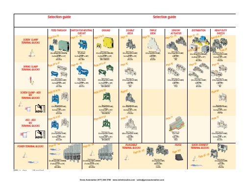
ABB EntrelecSommaireBU0402061SNC 160 003 C0205SummarySelection guide ....................................................................................page 1Screw clamp ........................................................................................page 2Feed through and ground terminal blocks .......................................................page 2 - 5 to 10Single pole, multiclamp terminal blocks..........................................................................page 4Feed through terminal blocks - Double-deck................................................................page 11Feed through terminal blocks - Triple-deck...................................................................page 12Three level sensor, terminal blocks without ground connection...................................page 13Three level sensor, terminal blocks with ground connection ........................................page 14Terminal blocks for distribution boxes, double deck + protection .......................page 15 - 16Interruptible terminal blocks for neutral circuit......................................................page 17 - 18Distribution : phase, ground terminal blocks .......................................................page 19 to 21Single pole or four pole distribution blocks..........................................................page 22 to 24Heavy duty switch terminal blocks with blade......................................................page 25 - 26Heavy duty switch terminal blocks with push-turn knob..............................................page 26Heavy duty switch terminal blocks with contact control pull lever...............................page 29Heavy duty switch terminal blocks with blade - Double-deck .....................................page 27Fuse holder terminal blocks for 5x20 mm (.197x.787 in.) and 5x25 mm (.197x.984 in.)or 6.35x25.4 mm (1/4x1 in.) and 6.35x32 mm (1/4x11/4 in.) fuse s.........................................page 28 - 29Fuse holder terminal blocks for 5x20 mm (.197x.787 in.) and 5x25 mm (.197x.984 in.) fuses -Double-dec k.....................................................................................................................page 27Terminal blocks for test circuits with sliding bridge ......................................................page 30Terminal blocks for metering circuits.............................................................................page 31ESSAILEC terminal blocks.............................................................................................page 32Safety connection terminal blocks ................................................................................page 33Miniblocks for EN 50045 (DIN 46277/2) rail ..........................................................page 34 - 35Spring clamp ......................................................................................page 36Angled terminal blocks - Feed through and ground .....................................................page 36Feed through and ground terminal blocks ...........................................................page 37 to 41Feed through terminal blocks - Double deck ................................................................page 42Terminal blocks for sensors / actuators ........................................................................page 42Terminal blocks for distribution boxes...........................................................................page 43Switch terminal blocks for neutral conductor........................................................page 44 - 45Heavy duty switch terminal blocks with blade..............................................................page 46Fuse holder terminal blocks for 5x20 mm (.197x.787 in.) and 5x25 mm (.197x.984 in.) fuse s....page 47Miniblocks Spring clamp ......................................................................................page 48 to 52ADO - Screw clamp ...........................................................................page 53Feed through and ground terminal blocks ...........................................................page 53 to 56Feed through and ground terminal blocks - Double-deck............................................page 57Heavy duty switch terminal blocks with blade..............................................................page 58Fuse holder terminal blocks for 5x20 mm (.197x.787 in.) and 5x25 mm (.197x.984 in.) fuse s ......page 59 - 60Miniblocks ADO - Screw clamp............................................................................page 61 to 65ADO - ADO .........................................................................................page 66Feed through and ground terminal blocks ...........................................................page 66 to 69Feed through and ground terminal blocks - Double-deck............................................page 70Terminal blocks for sensors / actuators ........................................................................page 71Heavy duty switch terminal blocks with blade..............................................................page 72Fuse holder terminal blocks for 5x20 mm (.197x.787 in.) and 5x25 mm (.197x.984 in.) fuse s ......page 73 - 74Miniblocks ADO - ADO .........................................................................................page 75 to 79Accessories ADO ...........................................................................................................page 80Power terminal blocks .............................................................page 81 to 84Quick-connect terminal blocks .................................................page 85 - 86Terminal blocks for railway applications ................................page 87 to 97Pluggable terminal blocks .....................................................page 98 to 100Accessories......................................................................................page 101Marking..................................................................................page 102 to 104GrossAutomation(877)268-3700··*************************PR30PR3.Z2PR3.G2PR5PR4PR1.Z2Rated wire size :Rated wire size :Rated wire size :Rated wire size :Mounting railsShield terminals forcollector barMarking tableHorizontal Rated wire size :0.5 to 16 mm² (22 to 8 AWG)Rated wire size :Rated wire size :Rated wire size :P a g e t o 29e30 t o 32ag e e3P a ge 8 t o 60a g e6t o 6574P a ge 7 t o 79P a ge 9P a g P a gGrossAutomation(877)268-3700··*************************2ABB Entrelecd010830402051SNC 160 003 C0205MA 2,5/5 - 2.5 mm² blocks - 5 mm .200" spacingAccessoriesGrossAutomation(877)268-3700··*************************3ABB Entrelec D010740402051SNC 160 003 C0205M 4/6 - 4 mm² blocks - 6 mm .238" spacingAccessoriesGrossAutomation(877)268-3700··*************************4ABB EntrelecD011030402051SNC 160 003 C0205M 4/6.3A - 4 mm² blocks - 6 mm .238" spacingM 4/6.4A - 4 mm² blocks - 6 mm .238" spacingGrossAutomation(877)268-3700··*************************5ABB Entrelec D010840402051SNC 160 003 C0205M 6/8 - 6 mm² blocks - 8 mm .315" spacingAccessoriesGrossAutomation(877)268-3700··*************************6ABB EntrelecD010850402051SNC 160 003 C0205M 10/10 - 10 mm² blocks - 10 mm .394" spacingAccessoriesGrossAutomation(877)268-3700··*************************7ABB Entrelec D010860402051SNC 160 003 C0205M 16/12 - 16 mm² blocks - 12 mm .473" spacingAccessoriesGrossAutomation(877)268-3700··*************************8ABB EntrelecD010870402051SNC 160 003 C0205M 35/16 - 35 mm² blocks - 16 mm .630" spacingGrossAutomation(877)268-3700··*************************M 95/26 - 95 mm² blocks - 26 mm 1.02" spacingM 70/22.P - 70 mm² ground block with rail contact - 22 mm .630" spacingSelection35 mm / 1.37"12 mm / 0.47"14-30 Nm / 124-260 Ib.in 1.2-1.4 Nm / 10.6-12.3 Ib.in1000600600415400400577070240 mm 2500 MCM 500 MCM 10 mm 2 6 AWG 6 AWG IEC UL CSANFC DIN0.5 - 160.5 - 100 AWG-600 MCM 2 AWG-500 MCM 50 - 30035 - 24018-6 AWGD 150/31.D10 - 150 mm² blocks - 31 mm 1.22" spacingCharacteristicsD 240/36.D10 - 240 mm² blocks - 36 mm 1.41" spacingSelectionWire size main circuit mm² / AWG VoltageV Current main circuit A Current outputARated wire size main circuit mm² / AWG Rated wire size outputmm² / AWG Wire stripping length main circuit mm / inches Wire stripping length output mm / inches Recommended torque main circuit Nm / Ib.in Recommended torque outputNm / Ib.inSolid Stranded Solid Stranded Wire size output mm² / AWG9.5 mm / .37"0.5-0.8 Nm / 4.4-7.1 Ib.in5003003003220204 mm 212 AWG12 AWG0.2 - 422-12 AWG 22-12 AWG 0.22 - 4IEC ULCSANFC DINCharacteristicsWire size mm² / AWGSolid Stranded D 4/6.T3 - 4 mm² blocks - 6 mm .238" spacingSelectionVoltage V CurrentARated wire sizemm² / AWG Wire stripping length mm / inches Recommended torqueNm / Ib.inM 4/6.T3.P - 4 mm² block - 6 mm .238" spacingD 2,5/6.D - 2.5 mm² blocks - 6 mm .238" spacingD 2,5/6.DL - 2.5 mm² blocks - 6 mm .238" spacingD 2,5/6.DPA1 - 2.5 mm² blocks - 6 mm .238" spacingD 2,5/6.DPAL1 - 2.5 mm² blocks - 6 mm .238" spacingD 4/6... - 4 mm² blocks - 6 mm .238" spacingD 4/6.LNTP - 4 mm² closed blocks - 17.8 mm .700" spacingMA 2,5/5.NT- 2.5 mm² block - 5 mm .200" spacingAccessories**SFB2 : 16 to 35 mm² 6 to 2 AWG H= 3 mm/.12"M 10/10.NT- 10 mm² block - 10 mm .394" spacingAccessories(1) Except for M 35/16 NT (closed block)*SFB1 : 0.5 to 35 mm² 18 to 2 AWG H= 7 mm/.28"**SFB2 : 16 to 35 mm² 6 to 2 AWG H= 3 mm/.12"MB 4/6... - 4 mm² blocks - 6 mm .238" spacingMB 6/8... - 6 mm² blocks - 8 mm .315" spacingMB 10/10... - 10 mm² blocks - 10 mm .394" spacingBRU 125 A - 35 mm² block - 27 mm 1.063" spacingBRU 160 A - 70 mm² block - 35.2 mm 1.388" spacingBRU 250 A - 120 mm² blocks - 44.5 mm 1.752" spacingBRU 400 A - 185 mm² block - 44.5 mm 1.752" spacingAccessoriesAccessoriesBRT 80 A - 16 mm² block - 48 mm 1.89" spacingBRT 125 A - 35 mm² block - 48 mm 1.89" spacingBRT 160 A - 50 mm² block - 50 mm 1.97" spacing9.5 mm / .37"0.5-0.6 Nm / 4.4-5.3 Ib.in4003003002010104 mm 210 AWG 12 AWG 0.5 - 422-10 AWG20-12 AWG0.5 - 2.5IEC ULCSANFC DINMA 2,5/5.SNB - 2.5 mm² blocks - 5 mm .200" spacingCharacteristicsM 4/6.SNB - 4 mm² blocks - 6 mm .238" spacingSelectionWire size mm² / AWGVoltage V CurrentARated wire sizemm² / AWG Wire stripping length mm / inches Recommended torqueNm / Ib.inSolid StrandedM 6/8.SNB - 6 mm² blocks - 8 mm .315" spacing - blade switchingSelectionAccessoriesM 4/8.D2.SF - for fuses 5x20 mm .197x.787 in. and 5x25 mm .197x.984 in. -4 mm² blocks - 8 mm .315" spacingM 4/6.D2.SNBT - 4 mm² blocks - 6 mm .238" spacing - blade switchM 4/8.SF- 4 mm² blocks - 8 mm .315" spacingM 4/8.SFL - 4 mm² blocks - 8 mm .315" spacing12 mm / .472"1.2-1.4 Nm / 10.6-12.3 Ib.in800(1)60060016252510 mm 210 AWG8 AWG0.5 - 1622-10 AWG 22-8 AWG 0.5 - 10IEC ULCSANFC DINCBD2SML 10/13.SF - for fuses 6.35x25.4 mm 1/4x1 in. and 6.35x32 mm 1/4x11/4 in. -10 mm² blocks - 13 mm .512" spacingSelectionAccessoriesCharacteristicsWire size mm² / AWGVoltage V CurrentARated wire sizemm² / AWG Wire stripping length mm / inches Recommended torqueNm / Ib.inSolid Stranded (1) Insulation voltage of terminal block - operating voltage : according to fuse.M 4/6.D2.2S2... - 4 mm² blocks - 6 mm .238" spacing11 mm / .43"0.8-1 Nm / 7.1-8.9 Ib.in50060030306 mm 28 AWG0.5 - 1022-8 AWG0.5 - 6IECULCSANFC DINM 6/8.ST... - 6 mm² blocks - 8 mm .315" spacingCharacteristicsWire size mm² / AWGVoltage V CurrentARated wire sizemm² / AWG Wire stripping length mm / inches Recommended torqueNm / Ib.inSolid Stranded M 6/8.STA - 6 mm² blocks - 8 mm .315" spacing(3)Only for M 6/8.STAM 4/6.ST- 4 mm² blocks - 6 mm .236" spacingBNT...PC...(2) Only for M10/10.ST-SnThe PREM IUM solution for testing the secondary circuits of current or voltage transformers.ESSAILEC, approved by the major electricity utilities, remains the premium choice for the energy market.Implemented in the transformers secondary circuits, ESSAILEC thanks to its intelligent “make before break” design eases and secures any intervention. Cutting the energy supply is avoided with zero risk for the operator.The plug and socket connection cuts cost installation as well as in-situ wiring errors. ESSAILEC is ideal for the wiring of sub-assemblies in the secondary circuits.ESSAILEC terminal blocksProtection relays,Protection relays,Testing :The ESSAILEC socket supplies energy to the protection or counting devices. The insertion of the test plug, which is connected to the measurement equipment, allows the testing of the devices, without perturbing the circuit.ESSAILEC blocks are well adapted to current or voltage measurement :-Current sockets with make before break contacts and pre-wired test plug for current measures-Voltage sockets with open contacts and pre-wired test plug for voltage measures-Up to 4 ammeters or 4 voltmeters connected to the test plugDistributing :The ESSAILEC plug is continuously mounted on the socket to supply current or voltage to secondary circuits sub assemblies.ESSAILEC blocks extreme versatility allow :-Safe current distribution with current socket with mobile contacts since the secondary circuit is not cut when plug is removed-Voltage or polarity distribution with dedicated voltage or polarity socket with closed contactESSAILEC is designed to offer :Great flexibility :-Connection multi contacts « plug and play »-Panel, rail, rack fixed mounting or stand-alone connector -Two wiring technologies, up to 10 mm²Extreme reliability :-Non symmetric blocks -Coding accessories -IP20 design -Locking system -Sealed coverR S T NFor technical characteristics and complete part numbers list, please ask for the ESSAILEC catalog10005006003225254 mm 21.65 mm²12 AWG 13 mm / .51"IECB.SCSANFC DINTS 50-180.5 - 0.8 Nm /4.4 - 7.1 Ib.in0.2 - 422-12 AWG0.22 - 40.5 - 1.50.28 - 1.6580050060041252562.512 AWG 13 mm / .51"0.8 - 1 Nm / 7.1 - 8.9 Ib.inIECB.S CSANFC DINTS 50-180.5 - 1020-12 AWG0.5 - 60.28 - 2.590050060046406510 mm 26 mm² 6 AWG 14 mm / .55"IECB.S UL/CSANFC DINTS 50-181.2 - 1.4 Nm / 10.6 - 12.3 Ib.in0.5 - 1620 - 6 AWG0.5 - 100.28 - 6M 4/6.RS - 4 mm² blocks - 6 mm .238" spacingCharacteristicsWire size mm² / AWGVoltage V CurrentARated wire sizemm² / AWG Wire stripping lengthmm / inches Recommended torque (screw)Nm / Ib.inSolid wire Stranded wire Solid wire Stranded wire Screw clampLugsM 6/8.RS - 6 mm² blocks - 8 mm .315" spacingCharacteristicsWire size mm² / AWGVoltage V CurrentARated wire sizemm² / AWG Wire stripping lengthmm / inches Recommended torque (screw)Nm / Ib.inSolid wire Stranded wire Solid wire Stranded wire Screw clampLugspending M 10/10.RS - 10 mm² blocks - 10 mm .394" spacingCharacteristicsWire size mm² / AWGVoltage V CurrentARated wire sizemm² / AWG Wire stripping lengthmm / inches Recommended torque (screw)Nm / Ib.inSolid wire Stranded wire Solid wire Stranded wire Screw clampLugspending SelectionAccessories(1) Only for block M 4/6.RS (4) For blocks M 4/6.RS and M 6/8.RS(2) Only for block M 6/8.RS(3) Only for block M 10/10.RSDR 1,5/4 - 1.5 mm² blocks - 4 mm .157" spacingDR 1,5/5... - 1.5 mm² blocks - 5 mm .200" spacing。
Nuvoton NuMicro ICP Programmer 用户指南(新唐MO51系列DOWNLOAD工具)

V1.17
Nuvoton NuMide
The information in this document is subject to change without notice. The Nuvoton Technology Corp. shall not be liable for technical or editorial errors or omissions contained herein; nor for incidental or consequential damages resulting from the furnishing, performance, or use of this material. This documentation may not, in whole or in part, be copied, photocopied, reproduced, translated, or reduced to any electronic medium or machine readable form without prior consent, in writing, from the Nuvoton Technology Corp. Nuvoton Technology Corp. All rights reserved.
2 Publication Release Date: Aug. 2011
Nuvoton NuMicro ICP Programmer User Guide
Table of Contents
1. 简介..........................................................
欧姆新文件服务用户指南说明书
EURONEXT FILES SERVICES Preface Document titleEURONEXT FILES SERVICESDocument type or subjectUser GuideVersion number Date1.2 26 May 2017Number of pages Author23 EuronextThis document is for information purposes only. The information and materials contained in this document are provided ‘as is’ and Euronext does not warrant the accuracy, adequacy or completeness and expressly disclaims liability for any errors or omissions. This document is not intended to be, and shall not constitute in any way a binding or legal agreement, or impose any legal obligation on Euronext. This document and any contents thereof, as well as any prior or subsequent information exchanged with Euronext in relation to the subject matter of this presentation, are confidential and are for the sole attention of the intended recipient. Except as described below, all proprietary rights and interest in or connected with this publication shall vest in Euronext. No part of it may be redistributed or reproduced without the prior written permission of Euronext. Portions of this presentation may contain materials or information copyrighted, trademarked or otherwise owned by a third party. No permission to use these third party materials should be inferred from this presentation.Euronext refers to Euronext N.V. and its affiliates. Information regarding trademarks and intellectual property rights of Euronext is located at https:///terms-use.© 2016 Euronext N.V. - All rights reserved.© 2016 Euronext N.V. - All rights reserved. i of 23 1.2PREFACEPURPOSEEuronext File Services is a Server providing files necessary for Euronext’s customers that have either an EMDDA (market data), SPA (Service Provider) or TPA (Trading Platform) agreement to get access to the core trading chain of Euronext. This document provides general technical information about Euronext’s File Services.This document intends to provide general technical information about Euronext File Services.TARGET AUDIENCEThe primary audience of this document is Developers, Exchange Connectivity Managers, Trading Support Teams and anybody involved in the setup and the configuration of Optiq MDG solution in End User Acceptance (EUA) and Production environments.ASSOCIATED DOCUMENTSThe following lists the associated documents, which either should be read in conjunction with this document or which provide other relevant information for the user:Euronext Cash and Derivatives Markets - Optiq MDG Client Specifications - v1.4.0CONTACTSFor any questions about this document or technical support please contact the Optiq Support Desk:Optiq Support DeskTel: +33 1 70 48 25 55******************WHAT’S NEW?The following lists only the most recent modification made to this revision/version. For the Document History table, see the Appendix.CONTENTS1.OVERVIEW (5)2.WHY CONNECT TO THE EURONEXT EFS SERVICE? (6)3.ACCESS TO EURONEXT FILE SERVICES USER INTERFACE (7)3.1 General Procedure (7)3.2 Detailed procedure (7)3.2.1Pre-requisite: company agreements (7)3.2.2Accessing the EFS User Interface (7)3.3 Supported Browsers (10)3.4 Protocol and Security (10)3.4.1HTTPS (10)3.4.2CA Certificate (10)3.4.3SSL configuration (11)3.5 Configuration (11)4.CURRENT FOLDERS STRUCTURE (12)4.1 p-EUA environment folder structure ............................................................ Erreur ! Signet non défini.4.1.1p-EUA environment folder content ............................................................................... E rreur ! Signet non défini.4.1.2Futures/ Current p-EUA environment folder content ................................................... E rreur ! Signet non défini.5.ACCESS TO EURONEXT FILE SERVICES USING RESTFUL API (13)5.1 introduction (13)5.2 Steps for accessing EFS (13)5.2.1Step 1 - Authentication (14)5.2.2Step 2 - Check if resource exists (16)5.2.3Step 3 - Browse the content of a folder (17)5.2.4Step 4 - Download a file (19)6.APPENDIX (22)6.1 RESTful API (22)1.OVERVIEWThe Euronext File Services is designed to centralize and provide access to configuration and data files for customers via SFTI network and/or Internet. This new critical service is based on a resilient and secured infrastructure.Customers covered by this Euronext File Services are companies who have signed one of the following agreements:■Euronext Market Data Distribution Agreement (EMDDA)■Service Provider Agreement (SPA)■Trading Platform Agreement (TPA)Euronext plans to leverage on the implementation of the European File Services going forward. The service will be used in the near future to host various files, generic or customized per member, thereby becoming the hub for any file transfer between Euronext and its customers.2.WHY CONNECT TO THE EURONEXT EFS SERVICE?Euronext EFS Services will host key configuration and data files that are to be used for OPTIQ MDG migration.The following files will be available per environment (v-EUA, p-EUA and Production):∙TimetableFile∙CashTickSizeReferentialFile∙SBETemplateAnd per Environment/Optiq Segment:∙OpenInterestFile∙PrevDayCapAndVolTradeFile∙FullTradeInformationFile∙CashStandingDataFile∙DerivativesStandingDataFile∙RepoSettlementPriceFile3.ACCESS TO EURONEXT FILE SERVICES USER INTERFACE3.1GENERAL PROCEDUREIn order to connect to the EFS, customers need to submit a request for a user ID through the Euronext Member Connectivity Administrator (MCA) web portal for each environment they want to access, i. e. p-EUA and Production.The user ID for each environment is emailed directly to the customer. With this id, the customer will be asked to connect once to the Euronext File Services to reset their password. Once this is complete, the user ID and the password can be used to login to the Service via a GUI (browser) or a RESTful API.Requests for p-EUA access will be processed under 2 working days. Customers can start placing their requests to access Production EFS. The requests will be processed at the end of April.During the first weeks after the launch of EFS in p-EUA and until the 6 of June, customers can use a generic user ID to access the Service. The user ID and password are available on the Home page of each customer’s MCA secured section of the Euronext web portal.3.2DETAILED PROCEDURE3.2.1Pre-requisite: company agreementsAs a pre-requisite, customers are required to have a company agreement signed with Euronext (EDDA, SPA or TPA).3.2.2Accessing the EFS User InterfaceTo access the EFS User Interface in both p-EUA and Production, the customers’ Member Connectivity Administrator (MCA) needs to connect to the Euronext web portal and fills the EFS form:https:///en/form/efs-login-creation.Only contacts registered as MCAs are allowed to access and fill the form. For more information about MCAs and their registration, please contact : ****************.MCA can order two types of accesses:-For a physical person : first name, last name, email address and phone number are required-For a software : application name, hostname must be provided3.2.2.1Confirmation of initial request for EFSEach subscriber will receive, in less than 48h following the initial request, an individual EFS subscriber confirmation email (see below). Follow the link and the steps provided in the email to activate the account and get access to the EFS.3.2.2.2Logging In via the user interfaceTo log in to the Euronext File Services application, do the following:1.Start your web browser2.Enter the appropriate test or production URL addressThe Euronext File Services Login box is displayed:3.Type your Euronext File Services username and password as provided by the Customer Access Service(CAS) team and click on the Login button.4.You are now logged on to the Euronext File Services home page.Please note:-If you have lost your password, you can use the “Forgot Password” link or contact ****************.-Subscribers must pay attention to the number of failed logons. After five (5) failed logon attempts (for incorrect username and/or password), their account will be locked. Participants need to contact the CAS team to reset their credentials.3.2.2.3Logging OutTo log out from the Euronext File Services User Interface, click Log Out (Sign-out) at the top right of the title bar, or simply close your browser.3.2.2.4Changing Your PasswordTo change your password, enter the old password, the new password and then confirm the new password. Click ‘done’.Passwords must be a minimum of eight (8) characters and contain the four character types listed below: -At least 1 upper case character – A-Z-At least 1 lower case character – a-z-At least 1 westernised Arabic numeral – 0-9-At least 1 special (non-alphanumeric) character [@#$%^&-+=_{}]Please note :-When logging in for the first time, you need to change your password.-Enter your user ID, then click on “Forgot Password” and follow the directions. You will be asked to enter your username, your email and a verification field to confirm you are not a robot.You can change your password at any time by clicking on “Change Password” at the top left of the window.3.3SUPPORTED BROWSERSThe Euronext File Service User Interface is compatible with the following browsers with Adobe Flash Player installed (at least Flash Player version 13):-Google Chrome-Safari-Internet Explorer 113.4PROTOCOL AND SECURITY3.4.1HTTPSThe EFS protocol is: HTTPS - Hypertext Transfer Protocol SecureThe HTTPS protocol can be used manually through a User Interface such as an Internet browser. Automatic transfer of files are also possible using the EFS API with a RESTful API client such as the Curl command line tool. Details about these methods to download files can be found in section 5.3.4.2CA CertificateCustomers must ensure their Entrust CA Certificate is up-to-date.To prevent any connectivity issue linked to an outdated root certificate, customers must download the latest version of the CA Certificate. Otherwise an error message such as “ curl: (60) Peer certificate cannot be authenticated with known CA certificates “ will appear during the connection phase.3.4.3SSL configurationThe supported TLS/SSL protocols to secure the connectivity are-TLSv1.1-TLSv1.2 (Recommended)The SSL Cipher Suite encryption options are :-Must use:o RSA Cipher Suites,o AES Cipher Suites,o SHA1 hashing Cipher suites.-Not allowed:o Null Ciphers,o Export grade ciphers,o Anonymous Ciphers (ADH),o3DES,o MD5/RC4 hashing-based Ciphers.3.5CONFIGURATIONThe following table provides the links to connect to Euronext File Services User Interface in the EUA and Productions environments.EUA (Test Environment) Production Disaster Recoveryhttps:/// https:/// https:/// Please note:To connect to EFS, the certificate needs the URL name. Connection to EFS must be done using the URL name.-On Internet, URL are provided and can be resolved by using the public DNS service.-On SFTI, if customers have access to Internet public DNS services, then the name can be resolved the same way. Howe ver if customers’ servers are not connected to Internet, then customers have two options:o Add the following mapping in the local DNSo Add the following mapping in the local host file of the server> 212.197.223.241 > 212.197.195.1 > 212.197.225.1 Here is the command to use to activate the session using curl :> curl https://:4434.CURRENT FOLDERS STRUCTUREFor all details on folder structure and naming convention please refer to the last Optiq file specification available here:https:///fr/optiq/documentation?quicktabs_188=1#quicktabs-188Today target for Optiq Step2 version of the document is version 2.0.0 (available on the following direct link):https:///sites//files/euronext_cash_and_derivatives_markets_-_optiq_files_specifications_-_v2.0.0.pdf5.ACCESS TO EURONEXT FILE SERVICES USING RESTFUL API5.1INTRODUCTIONEuronext provides a RESTful API to help customers develop applications to connect to EFS Services regardless of the development language used (see appendix for more information).The following sections describe how to connect to EFS, check for the availability of files and download them using the RESTful API. Equivalent commands and examples in Curl are also available. Curl is a command-line tool that uses URL syntax with a MIT/X derivative license to transfer data. More information is available at https://curl.haxx.se/).Please note:Euronext recommends to use Curl version 7.29 (Feb 2013) or later.FeaturesThere are three different ways to interact with EFS Services:-Check if a file or folder exists-Browse the content of the folder-Download a fileAccessThe RESTful API is accessible through Internet and SFTI. The selection of the EFS Services to access can be done in the Request Headers section by replacing the URL with the correct one.For example:-InternetGET https:///api/files/OptiqMDG/v-EUA/Current HTTP/1.1 -SFTIGET https://:443/api/files/OptiqMDG/v-EUA/Current HTTP/1.15.2STEPS FOR ACCESSING EFSPre-required step :1)Authentication (step 1)Possible scenarios and steps to follow:1)File name already known but never downloaded => Check if the file exists (step 2) and download itdirectly (step 4)2)File name already known and already downloaded at least once => Download the file directly withIf-Modified-Since condition (step 4)3)Unknown file name => Browse the content (step 3) and download the file (step 4)5.2.1Step 1 - AuthenticationRequest HeaderRequest BodyHere the equivalent command using Curl:Command1)If authentication information is invalid or omitted, the status code 401 will be returned:Response Header2)If authentication information is valid, an access token and its validity in minutes will be returnedwith status code 200:Response HeaderResponse Body5.2.2Step 2 - Check if resource existsTo prevent unnecessary download, customers have the possibility to check if a file exists before attempting to download it.Request HeaderAll API requests require to transport the session cookie and the authorization token.Here the equivalent command using Curl:Command1)If the resource doesn’t exist or if the session has expired, the status code 404 will be returned:Response Header2)If the resource exists, the status code 200 will be returned:Response Header5.2.3Step 3 - Browse the content of a folderRequest HeaderAll API requests require to transport the session cookie and the authorization token.Here the equivalent command using Curl:Command1)If the resource doesn’t exist or if the session has expired, the status code 404 will be returned:Response Header2)If the resource exists, the folder content will be returned with status code 200:Response Body Example5.2.4Step 4 - Download a fileRequest HeaderAll API requests require to transport the session cookie and the authorization token.The date when the file was downloaded for the last time must also be provided in order to prevent another download of the same file. This date is returned in the response header when the file is downloaded for the first time (see the third response case below).Command1)If the resource doesn’t exist or the session has expired, the status code 404 will be returned:Response Header2)If the resource exists but was not modified since the last download, the status code 304 will bereturned:Response Header3)If the resource exists, the file content will be returned with status code 200:Response HeaderResponse Body6.APPENDIX6.1RESTFUL APIREST (REpresentational State Transfer) is an architectural style for designing a web service, making maximum use of HTTP capabilities. Its main characteristics are as follows:1)Client / server application: transport over the network is provided by HTTP. Notice that EFS is basedon the HTTP secured protocol (HTTPS).2)Uniform interface: Any element offered by the application to handle is called a resource and isuniquely identified by the Uniform Resource Identifiers (URI below) according to the schema:https_URL = "https:" "//" host [":" port]Two types of URI schemes are distinguished:-URI member that designates a single resource.-URI collection that designates a list of resources of the same type.3)The semantic of messages from the client to the server is that of HTTP:-GET URI: retrieve the representation of a resource (URI member), or a list of resources (URI collection)-POST URI (collection): add a resource to a list of existing resources, thus creating a resource.-PUT URI (member): modify an existing resource or create a new resource.-DELETE URI: Destruction of one (URI member) or multiple (URI collection) resources.4)Server responses to clients also use HTTP messages, especially the following codes:-200 Ok-404 Resource Not Found on Server5)Representation of resources: the format with which a resource is represented is obtained bynegotiation using HTTP headers. The client specifies what it wants as the representation format with the header "Accept", the client and the server use the "Content-type" header to describe therepresentation format of the resource included in the message. The format used by EFS is JSON. Status codeThe following table shows the possible return codes for API requests.。
锐捷S5760交换机操作手册

1.2
1.4
2
1.4.1 Ping ..........................................................................................................................14 1.4.2 Traceroute..................................................................................................................15 基本功能维护与故障排查 ...............................................................................................................17 2.1 以太网接口维护...................................................................................................................17 2.1.1 端口协商...................................................................................................................17 2.1.2 流控设置...................................................................................................................17 2.1.3 端口状态监控............................................................................................................18 2.2 常见故障处理一:端口 LINK 状态异常 ................................................................................20 2.2.1 故障说明...................................................................................................................20 2.2.2 诊断流程...................................................................................................................20 常见故障二:端口丢包/错帧, 或 ping 包延迟大 ...................................................................21 2.3.1 故障说明...................................................................................................................21 2.3.2 诊断流程...................................................................................................................21 常见故障三:光模块无法 link-up 或出现大量 CRC ...............................................................22 2.4.1 故障现象...................................................................................................................22 2.4.2 诊断流程...................................................................................................................22 2.5 二层转发功能维护 ...............................................................................................................23 2.5.1 查看 MAC 地址表 .....................................................................................................23 2.5.2 常见故障排查............................................................................................................23 硬件转发功能维护与故障排查 ........................................................................................................24 3.1 3.2 底层命令简介 ......................................................................................................................24 基本命令 .............................................................................................................................24 3.2.1 L2 部分 .....................................................................................................................26 3.2.2 L3 部分 .....................................................................................................................28 3.3 PCL 部分 .............................................................................................................................30 3.3.1 ACL 应用 ..................................................................................................................31 3.3.2 端口安全...................................................................................................................33 3.3.3 Arp-check..................................................................................................................35 4 / 70
电信保护产品目录说明书

Contents70 Type indicating fuses —125 AC300 DC 1/10-101015087 holders for 70 Type fuses 130012Circuit protection for telecom applicationsTPC fuses and TPCDS pullout disconnects Telpower TPC compact current-limiting fuses mount in theTPCDS compact fused pulloutdisconnect that’s available intwo disconnect profiles anda variety of terminal styles.Recommended 0.75" center-to-center product spacing.Ratings•Volts 80 Vdc•Amps 3-125 A•IR 100 kAAgency information•UL Recognized (investigated to UL 1801) as a disconnect switch for the interruption of load current by means of withdrawing the fuse pullout•Recognized to US and Canadian requirements under the component recognition program of Underwriters Laboratories Inc. Files E219046 and E56412•CETypical applications•Telecommunications DC power circuit protection •Replacement of DC telecom circuit breakers•Applications where venting of arc or molten metals and gases during opening would pose a problem to surrounding devicesFeatures•Highest interrupting rating (100 kA) available and complete system coordination for DC circuit protection for compact footprint providing a superior protection solution for replacement of existing DC telecom circuit breakers•AmpColor ID™ system makes fuse replacement easy•Local and remote open fuse indication. Local alarm indication provided by LED on TPC fuse•Remote alarm terminal available in three positions common to DC circuit protection devicesTPC fusesTPC-4TPC-10TPC-30TPC-90TPC-5TPC-12TPC-40TPC-100TPC-6TPC-15TPC-50TPC-125TPC-7TPC-20TPC-60Data sheet no. 5023TPCDS catalog number systemTPCDS-BBE-2TPCDS-BSE-3TPCDS-SSM-1TPCDS-D-SEC2* TPCDS-BBE-3TPCDS-BSM-1TPCDS-SSM-2TPCDS-D-SMC1* TPCDS-BBM-1TPCDS-BSM-2TPCDS-SSM-3TPCDS-D-SMC2* TPCDS-BBM-2TPCDS-BSM-3TPCDS-D-BC1*TPCDS-BBM-3TPCDS-SSE-1TPCDS-D-BC2*TPCDS-BSE-1TPCDS-SSE-2TPCDS-D-CC1** Not investigated to Canadian requirements.Dimensions•See data sheet no. 5023T e l e c o m p r o t e c t i o n p r o d u c t sTPM fuse and TPMDS pullout disconnectTelpower TPM miniaturecurrent-limiting fusses mount in the miniature TPMDS pullout disconnect. The TPM fusesfeature local open fuse indication and TPMDS is easily integrated into remote indication systems.Ratings•Volts 80 Vdc •Amps 3-30 A•IR 20 kAAgency information•UL Recognized (investigated to UL 1801) as a disconnect switch for the interruption of load current by means of withdrawing the fuse pullout•Recognized to US and Canadian requirements under thecomponent recognition program of Underwriters Laboratories Inc. Files E219046 and E56412•CETypical applications•Telecommunications DC power circuit protection•Applications with restricted space, or mounting in 1 U (1.75"/44.5mm) panelsFeatures•Smallest and most versatile fused disconnect switch available allowing for assembly into 1 U (1.75"/44.5mm) panel. Easy to connect:•Load: 1/4" quick-connect or bolted connection with 10-32 (M5) captive nut•Line: 1/4" quick-connect or screw connection with clearance hole for #10 (M5) bolt•AmpColor ID™ System makes fuse replacement easy•Switch design provides for easy panel mounting by single captive 4-40 (M3) nut and panel notch integral to switch footprint•Complete system coordination capability with local and remote open fuse indication. Local alarm indication provided by LED on TPM fuse (maximum alarm circuit current: 20 mA)TPM fusesTPM-4TPM-7TPM-12TPM-25TPM-5TPM-8TPM-15TPM-30TPMDS pullout disconnects (accept all TPM fuse ampratings)TPMDS-MPullout fused disconnect, metric hardwareDimensions — see data sheet no. 5022Data sheet no. 5022TPMDS alarm schematicNotes:1. The resistance (R) must be provided by the end-user to limit the open fuse indication output current to a maximum of 20mA. The “R” value should be calculated using the system voltage value. If remote indication functionality is not required, the END-USER CIRCUITRY must still be supplied to provide aresistance path to the return for the local indication to properly function.2 The fuse is polarized to maintain proper orientation with the switch housing. The line and load terminals are identified on the switch housing.TP15900-4 fused pullout disconnect for TPA fuses 4-pole fused pullout disconnectfor use with Telpower TPA andTPA-B fuses. Pullout disconnectsfeature remote open fuseindication capability.Ratings•Volts•145 Vdc@40 A per pole•80 Vdc@50 A per poleAgency information•UL Recognized File E97649 as a disconnect switch for interruption of load current by means of withdrawing the fuse carrier•UL Recognized as a component for telecommunication power distribution equipment (UL category QPQY2)•UL Recognized fuses for branch circuit protection•CSA Component Acceptance for the system•CETypical applications•Telecommunications DC power circuit protectionFeatures•Easy installation, connects directly to busbar, reduces external wiring per pole. Rear accessibility for line and load terminations•LED alarm signaling (LED current 30 mA max)•Local and remote open-fuse indication along with fuse orientation rejection feature and fuse presence indication•Alarm test probe point allows on-site alarm circuit checkingTP15900-414-pole common disconnect w/ split alarm, split lineAvailable fusesTPA-B20, 25, 306520 kA Accessories•Spare fuse holders: catalog numbers 5TPH and TPSFH-ASDimensions — mm (in)TP15914 fused pullout disconnectModular 4-pole fused pulloutdisconnect for us with TPA fuses.4-poles per module can be gangedup to four modules for a total of16 poles. The TP15914 featuresopen fuse indication and fusepresence indication along with fuseorientation rejection.Ratings•Volts 145 Vdc•Amps 50 A max per poleAgency information•UL Recognized, Guide JFHR2, File E56412•UL Recognized as a disconnect switch for interruption of load current by means of withdrawing the fuse carrier•UL Recognized as a component for telecommunication power distribution equipment (UL category QPQYZ)•UL Recognized fuses for branch circuit protection•CSA Certified, Class 1422-30, File 53787•CSA Component Acceptance for the systemTypical applications•Telecommunications DC power circuit protectionFeatures•Easy installation with totally enclosed module that connects directly to busbar to reduce external per-pole wiring.•Standard front access load and line double lug connection for 8 AWG wire•LED alarm signaling (LED current 30 mA max)•Remote alarm with alarm test probe point to allow on-site alarmcircuit checkingTP15914-1Metric hardware Accessories•Spare fuse holders: catalog numbers 5TPH and TPSFH-ASDimensions — mm (in)Data sheet no. 5001Data sheet no. 5011TPA and TPA-B indicating fusesIndicating DC power distribution fuse for use inTP15900-4 and TP15914 fused pullout disconnects.Ratings•Volts•170 Vdc (TPA)•65 Vdc (TPA-B)•Amps•3-50 A (TPA)•20-30 A (TPA-B)•IR•100 kA (TPA)•20 kA (TPA-B)Agency information•UL Recognized, Guide JFHR2, File E56412•CSA Certified, Class 1422-30, File 53787•CE, RoHS compliantTypical applications•Telecommunications DC power circuit protectionFeatures•Indication pin provides for local and remote indication whenused with Bussmann series TP15900-4 and TP15914 disconnectswitches•Patented “orange ring” fuse orientation features assures correctfuse position•The UL Recognized ratings and current-limiting capabilitymake this fuse ideal for cable protection on existing DC powerdistribution systems•A unique blue label is used on all Telpower fuses to designate theirDC capabilityAccessories•Spare fuse holders: 5 position holder; 5TPH; 6 position holder;TPSFH-ASDimensions — in (mm)Data sheet no. 50122011/65/EU15800 fused pullout disconnect for the TPS fuseFused pullout disconnect switchfor use only with the TPS mainfuses (1 to 70 amp) and GMT-Aindicating fuse (see page 14-11).It is recommend to also use theGMT-X cover for the GMT-Afuse.Ratings•Volts 60 Vdc•Amps 3-70 A•SCCR 100 kAAgency information•UL Recognized, Guide QPQY2, File E97649•CETypical applications•Telecommunications DC power circuit protectionFeatures•Alarm output with wire wrap terminal or connection to 0.063”thick common alarm busAccessories•Spare fuse holders: catalog numbers TPSFH-AS (TPS fuses) andTPSFH-T (GMT fuses)Dimensions — in (mm)Data sheet no. 5002TP158HC fused pullout disconnectHigh amp panel mount, rear access fused pullout disconnect for use only with TelpowerTPL-B main fuses (70-250 A) and GMT-A indicating fuse (see page 14-11). It is recommend to also use the GMT-X cover for the GMT-A fuse.Ratings•Volts 80 Vdc •Amps 70-250 A•SCCR 100 kAAgency information•UL Recognized (investigated to UL 1801) as a disconnect switch for the interruption of load current by means of withdrawing the fuse pullout, Guide QPQY2, File E97649Typical applications•Telecommunications DC power circuit protectionFeatures•Similar profile, mounting method, and backplane configuration as 15800. The TP158HC can be installed into existing 15800 panels using the space of two 15800 pullout disconnects•Innovative new fuse pullout design eliminates need for tools to replace the Telpower type TPL-B fuse•Alarm output with wire wrap terminal or connection to 0.063 inch (1.6mm) thick common alarm bus•Hardware included: Load: washer, split lockwasher, and 5/16 - 18 nut (metric M8 x 1.25)TP158HC-MMetricAccessories•Spare fuse holders: TPSFH-LB (TPL-B fuses) and TPSFH-T (GMT fuses)Dimensions•See data sheet no. 5021Application notesThe line connection uses a 1/4-20 bolt (metric M6 x 1) that threads into the line terminal. The line terminal is designed with a float of ±0.02" (±0.50mm) to allow for variation in the distance between the TP158HC mounting flange and the line busbar (see dimensions). Equipment should be designed to eliminate any relative movement between the TP158HC mounting flange and the line busbar.The alarm circuit is not intended for pre-charging capacitive circuits. Maximum alarm circuit current 1 A.TPS main power fuseNon-indicating DC power distribution ferrule fuses specifically designed to meet the unique needs of DC power distribution systems. For use with Bussmann series 15800 fused pullout disconnect. Vertical and horizontal PCB tab versions available for circuit board applications.Ratings•Volts 170 Vdc •Amps 1-80 A•IR 100 kAAgency information•UL Recognized, Guide JFHR2, File E56412, RoHS compliant, CETypical applications•Telecommunications DC power circuit protection•Applications requiring printed circuit board mountingFeatures•The UL Recognized ratings and current-limiting capabilitymake this fuse ideal for cable protection on existing DC power distribution systems•A unique blue label is used on all Telpower fuses to designate their DC capability•PCB tab versions eliminate the need for fuseclips when mountingthe fuse on a circuit board* LB = Bolt tagAccessories•Spare fuse holder TPSFH-AS, see page 15-4Dimensions — in (mm)Data sheet no. 5009Data sheet no. 50212011/65/EUT e l e c o m p r o t e c t i o n p r o d u c t s15100 fused pullout disconnectFused pullout disconnect system for use with TPL Telpower fuses.Ratings•Volts 60 Vdc •Amps 70-800 A•SCCR 100 kAAgency information•UL Recognized, Guide QPQY2, File E97649•CETypical applications•Telecommunications DC power circuit protectionFeatures•Single-pole fusible disconnect switch for primary DC power distribution•Robust housing and terminal construction for demanding applications •Panel mounting•Easily connected to line or load bus15100-601300-800Dimensions — in (mm)Data sheet no. 5003TPHCS high current fused pullout disconnectHigh current fused pullout disconnect for use with TPL-B, TPL-C and TPH Telpower fuses. Available as acomplete pullout disconnect or just the pullout. Base may be purchased separately.Ratings•Volts 80 Vdc •Amps 70-800 A•SCCR 100 kAAgency information•UL Recognized (investigated to UL 1801) as a disconnect switch for the interruption of load current by means of withdrawing the fuse carrier•UL Recognized to meet the requirements for Canadian StandardsTypical applications•Telecommunications DC power circuit protectionFeatures•Innovative design eliminates needing tools to replace the TPL-B, TPL-C or TPH fuses•Easy to install with captive fasteners for direct busbar mounting (bolts not included). Standard 1/4” quick-connect for easy remote alarm connection•Optional electronic alarm eliminates needing parallel indicating fuses while providing local and remote open-fuse indication(maximum remote alarm current: 20 mA); Bipolar alarm: designed for both central office and Radio applications, Local LED open fuse indication for easy viewing.•Carrier window allows easy viewing of installed fuse amp rating•Compact design is ideal for today’s high power, high-densitycabinetsTPHCS250-E English TPL-B 70-250TPHCS250-MLMetric, LED TPL-B 70-250TPHCS250-EL English, LED TPL-B 70-250TPHCS250-MAV Metric, alarm TPL-B 70-250TPHCS250-EAVEnglish, alarm TPL-B 70-250TPHCS800-M Metric TPL-C or TPH 300-800TPHCS800-E English TPL-C or TPH 300-800TPHCS800-ML Metric, LED TPL-C or TPH 300-800TPHCS800-EL English, LED TPL-C or TPH 300-800TPHCS800-MAVMetric, alarm TPL-C or TPH 300-800TPHCS800-EAVEnglish, alarmTPL-C or TPH300-800TPHCS800-MAV shownData sheet no. 5020TPL high amp DC fusesHigh amp DC power distribution fuses for use with Telpower 15100, 15200, TP158HC and TPHCS fused pullout disconnects. TPL-TA adapter kit isnecessary when replacing a UBO fuse.Ratings•Volts 170 Vdc •Amps 70-800 A•IR 100 kAAgency information•UL Recognized Guide JFHR2, File E56412 Bellcore•CETypical applications•Telecommunications power circuit protectionFeatures•Current-limiting design for DC power distribution systems •UL Recognized branch circuit protection •Complete system coordination capability•Energy savings with low watts loss, low operating temperatures, and minimum I 2t levelsAccessories•Spare fuse holders: TPSFH-LB (for TPL-B fuses) TPSFH-LC (for TPL-C fuses)Dimensions — in (mm)Data sheet no. 5005TPL-CN, TPL-CR, TPL-CV and TPL-CZTPHCS800-P Pullout only (800 A)TPL-C or TPH300-800TPHCS-B-M Base only, metric —800 max TPHCS-B-E Base only, English —800 max TPHCS-B-ML Base only, metric, LED —800 max TPHCS-B-EL Base only, English, LED —800 max TPHCS-B-MAV Base only, metric, alarm —800 max TPHCS-B-EAVBase only, English, alarm—800 maxNotes1. TPHCS250 and TPHCS800 pullouts and bases are the same with exception to the fuse type the pullout will hold (TPL-B, TPL-C or TPH).2. Plastic rated UL 94V0, 140ºC RTI.Dimensions — mm (in)Data sheet no. 5020T e l e c o m p r o t e c t i o n p r o d u c t sTPN high amp current limiting DC fusesThe TPN fuse is a current-limiting DC power distribution fuse that’s dimensionally similar to UL Class R branch circuit fuses making them easy to install using standard RM60_ modular Class R fuse blocks.Ratings•Volts 170 Vdc •Amps 1-600 A•IR 100 kAAgency information•UL Recognized, Guide JFHR2, File E56412Typical applications•Telecommunications power circuit protectionFeatures•Current-limiting design for DC power distribution systems •Recognized branch circuit protection •Complete system coordination capability•Energy savings with low watts loss, low operating temperatures, and minimum I 2t levelsTPN-3TPN-35TPN-100TPN-300TPN-5TPN-40TPN-110TPN-350TPN-6TPN-45TPN-125TPN-400TPN-10TPN-50TPN-150TPN-450TPN-15TPN-60TPN-175TPN-500TPN-20TPN-70TPN-200TPN-600TPN-25TPN-80TPN-225Accessories•Spare fuse holders:TPSFH-N30 (for TPN 1-30) TPSFH-N60 (for TPN 35-60)Recommended modular* Class R fuse blocksRM25060-1CR 60RM25100-1CR 100RM25200-1CR 200RM25400-1CR 400RM25600-1CR600* Blocks can be snapped together to create the number of required poles. Optional indicating and non-indicating finger-safe covers available for all blocks.Data sheet no. 50060.81(21)35 A to 60 A0.5670A to 100A110A to 200A225A to 400A1.56(38)1.06(27)Dimensions — in (mm)70 Type pin indicating fusesPin indicating fuse for use in the 15087 panel-mount fuse holder. Ratings•Volts•125 Vac•300 Vdc•Amps 1/10-10 A•IR 1 kA @ 300 VdcAgency information•UL Recognized, Guide JDYX2, File E19180 Bellcore•CE70R-15/100A*Red/White101384550KS23751-L11 70E-18/100A*Y ellow100203363KS23751-L5 70X-2/10A Black——70F-1/4A*Violet100203371KS23751-L6 70K-1/4A*Violet/White100203405KS23751-L9 70G-1/2A*Red100203389KS23751-L7 70H-3/4A*Brown100203397KS23751-L8 70I-1A Pink——70A-1-1/3A*†White100203322KS23751-L1 70B-2A*Orange100203330KS23751-L2 70C-3A*Blue100203348KS23751-L3 70J-3-1/2A Black/White——70D-5A*Grn/Black100203355KS23751-L4 70L-6A Grn/White——70M-8A Brown/White——70N-10A Violet/Y ellow——72A Plastic Case (dummy)100203421—72B Blister Pack (dummy)103757977—* Product designed to comply with Bellcore Technical Reference TR-TSY-000799 Issue 1, December 1988.† Not UL Recognized.Data sheet no. 500715087 fuse holderPanel mount fuse holder for use with 70 Type fuses.Ratings•Volts 300 Vdc•Amps 12 AAgency information•UL Recognized, Guide IZLT2, File E14853•CEFlammability rating•UL 94V0Catalog number 15087Typical applications•Telecommunications DC power circuit protectionFeatures•Panel mount fuse holder for 70 type fuses supplied with two screws•Remote alarm capabilityOptional color-code eyeletsColor-coded eyelets are used with the fuse holder to indicate itsfuse amp rating.1A1706-0118/100Y ellow1A1706-151/10Gray/White 1A1706-022/10Black1A1706-031/4Violet1A1706-041/4Violet/White 1A1706-051/2Red1A1706-063/4Brown1A1706-071Pink1A1706-081-1/3White1A1706-092Orange1A1706-103Blue1A1706-163-1/2Black/White 1A1706-115Green/Black 1A1706-126Green/White 1A1706-138Brown/White 1A1706-1410Violet/YellowData sheet no. 5007Telecom protection products — 14HLS, HLT, PCT holders for GMT indicating fusesConfigurable fuse holders for use with GMT indicating fuses:•PCT single-pole•HLS 1-25 pole without flanges•HLT 1-25 pole with flangesRatings•Volts 60 Vdc/125 Vac •Amps 15 A per pole•Poles Up to 25 (HLT , HLS)Agency information•UL Recognized, Guide IZLT2, File E14853, 15 A (60 Vdc)•CEFlammability rating•UL 94V0Typical applications•Telecommunications DC power circuit protectionFeatures•Multiple configurations provide application flexibility•Compact size saves spaceHLS 1-25HLT1-25To order, see data sheet no. 5010 for build-a-code to determine:•Body style (HLT or HLS) •Number of poles •Busbar type •Busbar position•Termination locationData sheet no. 5010GMT indicating fuses for HLS, HLT, PCT holdersFast-acting indicating fuses for HLT , HLS and PCT fuse holders.Ratings•Volts•60 Vdc•125 Vac•Amps 18/100 to 15 A•IR•450 A@60 Vdc•300 A@125 VacAgency information•UL Recognized, Guide JFHR2, File E56412•RoHS compliant, CETypical applications•Telecommunications DC power circuit protectionFeatures•Local and remote indication capability•Color coded for easy amp rating identificationGMT-65/100A Black GMT-10A Red/White GMT-3/4A Brown GMT-12A Y ellow/Green GMT-1A Gray GMT-15A Red/Blue GMT-1-1/3A White GMT-Dummy Gray body GMT-1-1/2A White/Y ellow GMT-X Clear cover GMT-2A Orange GMT-YClear cover w/tabGMT-3ABlue* Some GMT ratings may be sold only in bulk pack.Accessories•Spare fuse holder, catalog number TPSFH-TGMT-A fast-acting, open fuse indicatorFast-acting GMT-A open fuse indicator is designed specifically for use in the Telpower 15800 and TP158HC fused pullout disconnects as a means of providing main fuse open indication.Agency information•UL Recognized, Guide JFHR2, File E56412 •RoHS compliant•CECatalog no./color code: GMT-A/YellowGMT - Dummy2011/65/EU2011/65/EUData sheet no. 500814-11BUSSMANN SERIES FULL LINE CATALOG 1007 — OCTOBER 2018/bussmannseriesWith the Bussmann TM series Quik-Spec™ Coordination Panelboard (QSCP), it’s simple and cost-effective to selectively coordinate using published circuit breaker/fuse and fuse/fuse ratio tables.What’s more, the compact panelboard features a footprint equal to circuit breaker panels but 40% smaller than traditional fusible panels. Its safety-focused design includes finger-safe branches, branch fuse interlock and fuse ampacity rejection.And with up to 200 kA short-circuit current rating (SCCR), the QSCP easily withstands high fault currents.Learn more at /bussmannseries .SERIESFollow us on social media to get the latest product and support information.Selective coordination has never been easier.。
toolmaRk 0.0.1 软件包用户手册说明书

Package‘toolmaRk’October14,2022Type PackageTitle Tests for Same-Source of ToolmarksVersion0.0.1Date2018-01-10Author Jeremy Hadler[aut,cre],Max Morris[ths],Heike Hofmann[ctb]Maintainer Jeremy Hadler<******************>DescriptionImplements two tests for same-source of toolmarks.The chumbley_non_random()test fol-lows the paper``An Improved Version of a Tool Mark Comparison Algorithm''by Hadler and Mor-ris(2017)<doi:10.1111/1556-4029.13640>.This is an extension of the Chumbley score as previ-ously described in``Validation of Tool Mark Comparisons Obtained Using a Quantitative,Com-parative,Statistical Algorithm''by Chumbley et al(2010)<doi:10.1111/j.1556-4029.2010.01424.x>.fixed_width_no_modeling()is based on correlation measures in a dia-mond shaped area of the toolmark as described in Hadler(2017).Depends R(>=3.3),plyr(>=1.8.4),dplyr(>=0.7.2),reshape2(>=1.4.2)Imports ggplot2(>=2.2.1)License GPL-3LazyData trueRoxygenNote6.0.1NeedsCompilation noRepository CRANDate/Publication2018-01-1610:37:45UTCR topics documented:ameslab (2)chumbley_non_random (3)fixed_width_no_modeling (3)Index512ameslab ameslab Toolmark profiles datasetDescriptionData set of toolmarks(profiles)created by screwdrivers under different angles.Tool mark data included here were produced by Prof.Scott Chumbley,Mr.Stephen Davis,Ms.Taylor Grieve,Mr.Ryan Spotts,and Dr.Jeremy Hadler.These data were produced as part of research performed at the Ames Laboratory,located on the Iowa State University campus.Ames Laboratory is operated for the U.S.Department of Energy by Iowa State University under Contract No.DE-Ac02-07CH11358. UsageameslabFormatthe dataset consists of a sample of16toolmark profiles and descriptors.Toolmarks with the same toolmark identifier are known matches,all other profiles are known non-matches.ID toolmark identifier.Factor variable.side A or B,indicates the side of the screwdriverused to create the toolmark.Factor variable.angle degree under which the toolmark was created.rep replicate number for a toolmark,side,angle composition.Note that the data here provided is not complete.For a more complete data set or more information please contact the references given below.profile list of data sets with one profile each.Measurements are taken at equispaced intervals across the toolmark..ReferencesTool mark data included here were produced by Prof.Scott Chumbley,Mr.Stephen Davis,Ms.Taylor Grieve,Mr.Ryan Spotts,and Dr.Jeremy Hadler.These data were produced as part of research performed at the Ames Laboratory,located on the Iowa State University campus.Ames Laboratory is operated for the U.S.Department of Energy by Iowa State University under Contract No.DE-Ac02-07CH11358.Examplesdata(ameslab)plot(ameslab$profile[[1]]$V1)chumbley_non_random(ameslab$profile[[1]],ameslab$profile[[2]])res14<-fixed_width_no_modeling(ameslab$profile[[1]],ameslab$profile[[4]])res14$dist_pvalchumbley_non_random3 chumbley_non_random Chumbley Non-RandomDescriptionThis function computes the Chumbley U-Statistic on systemically chosen pairs of windows rather than the original method which selects randomly chosen pairs of windowsUsagechumbley_non_random(data1,data2,window_opt=500,window_val=50,coarse=0.25)Argumentsdata1Thefirst tool mark as a1-column matrixdata2The second tool mark as a1-column matrixwindow_opt size of the window to be used in the optimization stepwindow_val Size of the window to be used in the validation stepcoarse smoothing parameter for the normalization smoothValuelist with•same_shift_n Number of same shift offsets used•diff_shift_n Number of different shift offsets used•U observed U statistic•p_value Corresponding p-valuefixed_width_no_modelingDistance/threshold test for toolmarksDescriptionCompute all possible correlations for windows of length n between the class components.Deter-mine the location of the maximized correlation.Given this location,create a diamond around it in the individual matrix of correlations For each offset in this diamond,compute the maximized correlation(1)Determine the distance between the offset for the class and indiviudal components(2)Compute the Threshold test statistics4fixed_width_no_modelingUsagefixed_width_no_modeling(dat1,dat2,coarse=0.25,fine=0.01,window.size=0.6,M=500)Argumentsdat1a one column matrix representing a digitized tool markdat2a one column matrix representing a second digitized tool markcoarse normalization smoothing parameterfine decomposition smoothing parameterwindow.size desired window size for the correlations to computeM search area restrictionValuelist with•"max_corr"maximized indiviudal component correlation•"Smooth_offset"optimal Class offset•"Resid_offset"optimal individual offset•"dist_pval"distance p-value•"thresh_pval"threshold p-value•"Above"Number of offsets with correlation bigger than threshold•"total_thresh"2*M+1•"mark1_decompostion"plot of decomposition d1•"mark2_decompostion"plot of decomposition d2•"class_correlations"plot of class correlation•"individual_correlations"plot of individual correlation•"distance_plot"distance_plot•"threshold_plot"threshold_plotIndex∗datasetsameslab,2ameslab,2chumbley_non_random,3fixed_width_no_modeling,35。
- 1、下载文档前请自行甄别文档内容的完整性,平台不提供额外的编辑、内容补充、找答案等附加服务。
- 2、"仅部分预览"的文档,不可在线预览部分如存在完整性等问题,可反馈申请退款(可完整预览的文档不适用该条件!)。
- 3、如文档侵犯您的权益,请联系客服反馈,我们会尽快为您处理(人工客服工作时间:9:00-18:30)。
输出信号(63=0~5V,7=0~10V,8=4~20mA) 型号
TEL:0750-6655202
4/4
∳䮼Ꮦᅝ⋄电子有限公司
标准输出信号包括0~5V、0~IOV和4~20mA。压力端口包括1/4-18NPT外螺纹、1/4BSP(G1/4)外螺纹和7/16-20 SAE-4外螺纹。
特点
应用
• 0.05%的精确度〔典型值) • 0.25%总误差(-25~85℃,典型值) • IP65,NEMA4,100%不锈钢隔离 • MEMS硅压阻式传感器,具有最小压力迟滞 • 先进的温度和非线性数字补偿功能 • 可提供CE认证产品 • 优异的性价比 • 可提供特殊压力端口、输出信号和电气连接
US10,000系列产品采用了316 L不锈钢压力端口、隔离式膜片结构和坚固的保护外壳(IP65))。数字补偿技术保 证了模拟输出信号下完整的信号调理。输出信号包括3线模拟电压输出和4~20mA二线制环路输出。
US10,000系列产品曾数千次地在航空和汽车工业的试验台上经受了考验。由于该产品优异的精度和极具竞争力 的价格,因此受到众多需要进行高精度测量的OEM客户的青睐。
bara
• • • • • • • • • • • • • •
单位
%Span %Span %Span %Span
kHz %Span
Ω MΩ °C °C °C Rated Rated
g g Million grams
备注 1 1 2
3
4 5 6
TEL:0750-6655202
2/4
• 军用/航空实验台 • 汽车实验台 • 校准设备 • 高端工业机械 • 固定电动机燃料控制
TEL:0750-6655202
1/4
∳䮼Ꮦᅝ⋄电子有限公司
US10000高性能不锈钢压力变送器
标准量程
量程
psig
psia
量程
barg
0~5
•
0~15
•
0~30
•
0~50
∳䮼Ꮦᅝ⋄⬉ᄤ有限公司
US10000高性能不锈钢力变送器
CE规范说明
IEC 61326 IEC 55022 Emissions Class A & B IEC61000-4-2 Electrostatic Discharge Immunity IEC61000-4-3 EM Field Immunity IEC61000-4-4 Electrical Fast Transient Immunity IEC61000-4-8
最小值 -0.25 -0.25 -0.1
1 0.5
10 -25 -25 -40 3X 4X ±20 100 1
典型值 0.1 0.1 0.05 0.1
.25
最大值 0.25 0.25 0.1
0.5 20
+85 +85 +125
与316L不锈钢兼容的各种介质 IP65(电缆输出型)
备注: 1. 输出与供电成比例。 2. 最佳拟和直线。 3. 总误差包括精确度、温度误差、零点和量程误差。 4. 4倍量程或15000Psi,取较小值,某些量程产品可达10倍。请与厂家联系 5. 参照MIL-STD-810C,程序514.2,图514.2-2,曲线L。 6. 1/2正弦波,参照MIL STD 202F,方法213B,条件A。
US10000高性能不锈钢压力变送器
• 数字补偿 • 高精度 • 压力校正标准 • EMC认证
产品说明
US10,000系列是美国MEAS公司推出的可应用于恶劣环境下的高精度压力传感器首选产品。其0.05%的精确度和 025%的总误差(典型值)提供了一个稳定的平台,特别适用于各种试验台和高精度工业压力应用。该产品采用了MEAS 独有的固态超稳技术(UltraStable),从而具有优异的稳定性。这种基本MEMS技术的传感器保证了在较宽温度范围 内良好的稳定性,同时具有优异的重复性和极小的迟滞。
外形尺寸
压力接口 见表1
电缆
电缆线(带热缩管) 通气管
标签
通气管
电气连接
电源+(红色) 输出+(绿色) 输出-(黑色) 电源-(白色)
4~20mA输出型
电源+(红色)
输出(黑色)
配套插头: 带通气孔连接器:
压力接口 见表1
连接器
标签
编号
表1 电气接口
接口
6针Bendix Boyonet 连接器
电气连接
•
0~75
•
0~100
•
0~200
•
0~300
•
0~500
•
0~1k
•
0~1.5k
•
0~3k
•
0~5k
•
0~10k
•
•
0~0.35
•
•
0~1
•
•
0~2
•
•
0~3.5
•
•
0~5
•
•
0~7
•
•
0~10
•
•
0~20
•
•
0~35
•
•
0~70
•
•
0~100
•
•
0~200
•
•
0~350
•
•
0~700
•
性能参数
参考温度:25℃(除非另有说明)
输出选项
编号
6 7 8
输出
0–5V 0 – 10 V 4 – 20 mA
产品选型示例
US165-000005-100PG
最小 8 15 9
供电(V) 典型
最大 30 30 30
压力类型(A=绝压,G=表压) 压力单位(P=Psi,B=Bar) 压力范围(300=300,05K=5000,3.5=3.5) 压力接口(2=1/4-19BSP,4=7/16-20UNF,5=1/4-18NPT)
电压输出 脚A:电源+ 脚B:输出+ 脚C:电源- 脚D:输出- 脚E:不用 脚F:通气孔 注:脚C和D内部连接
4~20mA输出 脚A:电源+ 脚D:输出 脚F:通气孔
TEL:0750-6655202
3/4
∳䮼Ꮦᅝ⋄电子有限公司
US10000高性能不锈钢压力变送器
参数 零点偏差 量程偏差 精度(结合非线性,迟滞和重复性) 长期稳定性(1年) 响应频率(-3dB) 总误差(补偿温度范围内) 输出阻抗(0~5V,0~10V) 绝缘电阻(绝缘电阻) 补偿温度 工作温度 贮存温度 过载压力 破坏压力 振动 冲击(11mS) 压力循环(从零到满量程) 重量 介质兼容性 防护等级 其它规格参数,请与厂家联系。