PSA_PSB系列小型高精度压力传感器_控制器
森萨塔传感器产品介绍

德州仪器半导体技术有限公司Sensata Technologies, Inc. 全球总部德州仪器传感器和控制器事业部转让给贝恩投资有限公司的事宜已于4月28日完成。
我们将以森萨塔科技(Sensata Technologies)的名称开始我们的业务。
Sensata Technologies 的品质核心是来源于我们的员工和全球各地的业务中心为用户和供应商提供的优质产品、技术创新和竭诚服务。
这些也都是您所期望的,我们依然会一如既往地保持下去。
纵观全球,很少有公司能像Sensata Technologies一样具有如此的全球覆盖性,我们在传感器和控制器上90年的努力耕耘,让我们可以同时拥有传感器和控制器这样广泛的产品组合,使我们在专业技术领域的深度达到世界领先地位。
作为一家独立的新公司,“Sensata Technologies”将为我们全球的客户,供应商和全体员工开启新的契机。
我们的email地址和网站域名都将变为;然而发送至的email将会被转入我们的域名,并且人们登陆/snc网址也将自动转到我们新的网址。
商务和技术中心z 客户服务z销售/ 市场z 设计z新产品研发z过程研发最具成本竞争力产地z 生产z生产计划z制作z质量z采购专业中心•全球市场•全球化设计•产品专门化•全球化协作•专门化管理最具成本竞争力生产地商务&技术中心荷兰,AlmeloAttleboro, USA墨西哥,Aguascalientes中国常州Sensata Technologies, Inc.Campinas Aguascalientesn F应丆忢廈拞崙Chinchon 韩崙Kuala Lumpur 马棃惣亚我们是顾客的全球合作伙伴ALMELO 兰Freising,ATTLEBORO美国OYAMA Dallas, TX Tokyo C Novi, MI Seoul 韩崙汽车传感器产品研发中心及业务中心汽车传感器产品生产工厂技术研发中心实验室¾计量实验室符合ISO10012-1要求¾表面分析实验室-SEM-EDAX -Auger microscopy ¾金相实验室¾环境测试实验室-振动-湿度-机械冲击-腐蚀-海拔-热冲击-热循环-寿命循环¾化学实验室-原子能辐射及吸收光谱法-傅立叶变换红外光谱分析符合ISO/IEC 指南第25款“检定及测试实验室必备条件”¾寿命测试实验室-多种产品品质检测仪器-液压、气压压力循环设备-热循环和热冲击测试箱¾传感器原型实验室-玻璃焊接-厚膜工艺-导线的焊接¾电磁兼容性测试实验室-带状线测试200V/m, 500kHz -1GHz -大电流测试-ESD调宯统嬻调宯统·压力传感器·双态压力开关·相对湿度和温度传感器·空气质量传感器变懍敔宯统•PSM组合压力开关·档位传感器·压力传感器·压力/温度式传感器发动婘宯统•MAP 歧管绝对压力传感器•T-MAP传感器•缸内直喷压力传感器•共轨压力传感器•MAF空气流量传感器•DPS压差传感器•排气背压传感器•缸压传感器•机油压力传感器掙盘峊惂宯统·压力传感器及压力开关-动力转向-制动系统·真空助力器压力传感器·踏板压力传感器·弱加速度传感器•OWS座椅承重传感器传感器市场及应用(汽车行业)提供全球最具竞争力的全系列汽车压力传感器压力范围应用测量型式产品技术1 Bar微粒捕捉器(柴油机)压差式微机电结构(MEMS)1 Bar EGR压差式陶瓷电容(APT)1 Bar歧管压力(MAP)绝对压力陶瓷电容(APT)3 Bar增压压力(Boost)绝对压力陶瓷电容(APT)5 Bar排气背压相对压力陶瓷电容(APT)6 Bar氢燃料电池相对压力陶瓷电容(APT)7 Bar电子油泵控制(GDI系统)相对压力陶瓷电容(APT)8 Bar机油压力相对压力陶瓷电容(APT)10 Bar CNG/LPG相对压力硅应变片技术(MSG)12 Bar自动变速箱相对压力陶瓷电容(APT)20 Bar双离合器变速箱.绝对压力陶瓷电容(APT)70 Bar CVT, AMT相对压力陶瓷电容(APT)100 Bar四轮驱动相对压力陶瓷电容(APT)100 –200 Bar汽油直喷(GDI)相对压力硅应变片技术(MSG)200 Bar缸压传感器相对压力硅应变片技术(MSG)400 Bar储氢罐相对压力特殊的硅应变片技术(MSG)1800-2600 Bar共轨压力相对压力硅应变片技术(MSG)N/A OWS座椅承重传感轴向力硅应变片技术(MSG)MEMS 技术APT 技术MSG 技术公认的供货能力及产品可靠性¾1988年起从事汽车传感器业务已有超过16年的历史。
PS300系列智能压力传感器
PS300系列智能压力传感器
佚名
【期刊名称】《《军民两用技术与产品》》
【年(卷),期】2010(000)009
【摘要】德国图尔克公司推出了一款多种压力单位可选的PS300系列智能压力传感器。
该系列智能压力传感器具有坚固的外壳及IP68/IP69K防护等级.压力测量范围为一0.1MPa~60MPa.适用于安装在各种液压系统中.尤其适合在恶劣环境中使用。
【总页数】1页(P30-30)
【正文语种】中文
【中图分类】TP212
【相关文献】
1.图尔克推出应用于液压系统的PS300系列智能压力传感器 [J],
2.图尔克PS300系列智能压力传感器 [J],
3.图尔克推出Ps300系列智能压力传感器 [J],
4.应用于液压系统的PS300系列智能压力传感器 [J],
5.台达推出DPA系列智能化新一代微型压力传感器 [J],
因版权原因,仅展示原文概要,查看原文内容请购买。
压力控制器使用说明
压力控制器以及压力开关产品使用手册目录第一章MD-S200 电池供电型数字压力表使用手册第二章MD-S500数字式远传型压力表使用手册第三章MD-S600高精度智能压力开关使用手册第四章MD-S700机械式压力开关使用手册第五章MD-S800低成本压力开关使用手册第六章MD-S910W/910C水泵压力控制器/空压机控制器使用手册第七章MD-S910F分体式压力控制器使用手册第八章MD-S系列产品的安装与电气连接第九章MD-S系列产品的日常养护第十章产品的运输与保存第十一章常见故障及解决办法第十二章 MD-S系列产品质量保证服务主要特点:※技术先进,质量控制体系严格,通过权威认证※设计时的第一原则是:实用及安全的原则※全系列通过权威认证注意:1.请留意手册中出现的带有※(!)(?)等提醒字样的语言!2.文中出现的“不得”“禁止”等明显禁止的语言时,请注意严格按照其要求操作。
第1章MD-S200电池供电型数字压力表MD-S200电池供电型智能压力表是是集压力测量、显示一体的高精度电子式压力表,具有抗震动、显示精度高、使用寿命长、可清零、自动待机等特点。
无需外接电源,电池供电时间长,具有自动待机与一键清零功能,使用方便,应用领域广泛。
一.外形图1.压力显示窗口2.设置键(SET)3.压力安装接口二.系统参数压力量程0-1.6MPA 或定制量程安装接口M20*1.5精度等级0.5%显示位数4位LCD显示背光蓝色背光尺寸直径100mm 厚度48m供电 4.5V 三节5号电池功耗0.001W电池更换通常每12个月更换一次电池(以实际使用耗电量为准)使用温度-20~60℃功能 1.实时显示压力 2.自动休眠 3.一键清零 4.单位切换三.按键定义说明设置键(SET)键:1.短按SET键一次,背光亮。
2.连续短按SET键,压力的显示单位在Mpa,Kg,PSI之间切换,默认单位为Mpa。
四.一键清零功能操作方法:长按SET键5秒,可以一键清零。
DEH德文缩写

FD4MN 高压蒸汽阀4位置控制器最小输出
FD4MX 高压蒸汽阀4位置控制器最大输出
FD4OB 高压蒸汽阀4允许范围开始点
FD4OE 高压蒸汽阀4允许范围结束点
FD4OK 高压蒸汽阀4关闭时间测量OK
FD4R 高压蒸汽阀4位置控制器
FD4Z 高压蒸汽阀4关闭
FDS4OK 高压蒸汽阀4ESV关闭时间测量OK
FDS4Z 高压蒸汽阀4ESV关闭
FDSFG 释放高压蒸汽压力设定值
FDSV 高压蒸汽压力延时设定值
FDSVK 高压蒸汽压力延时和正确的设定值
FDSX 高压蒸汽压力外部设定值
FDXW 高压蒸汽压力调节偏差
FGDGR 释放喷嘴组控制监视
FGSWF 速度设定值控制释放
FD3MX 高压蒸汽阀3位置控制器最大输出
FD3OB 高压蒸汽阀3允许范围开始点
FD3OE 高压蒸汽阀3允许范围结束点
FD3OK 高压蒸汽阀3关闭时间测量OK
FD3R 高压蒸汽阀3位置控制器
FD3Z 高压蒸汽阀3关闭
FD4 高压蒸汽阀4
FD4A 高压蒸汽阀4打开
FD4AP 高压蒸汽阀4运行点
HATRIE 高压排汽温度调节器激活
HATRKP 高压排汽温度调节器比例增益
HATRTN 高压排汽温度调节器内部时间
HATS 高压排汽温度调节器设定值
HDU 高压旁路站
HER 抽热压力调节器
HERIE 抽热压力调节器激活
HERS 抽热压力调节器设定值
HFD1 高压阀1实际位置
HFD2 高压阀2实际位置
NSVGSY 同期时延时速度设定值变化率
仿真软件MATLABPSB与PSASP模型及仿真分析
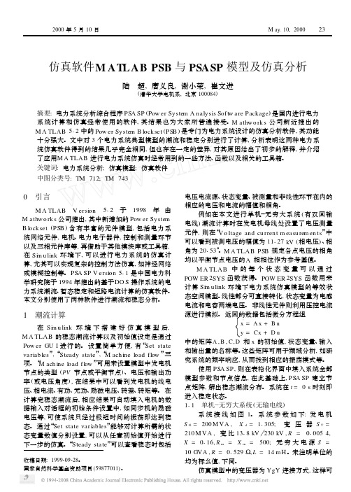
仿真软件M AT LAB PSB 与PSASP 模型及仿真分析陆 超,唐义良,谢小荣,崔文进(清华大学电机系,北京100084)摘要:电力系统分析综合程序PSA SP (Pow er System A nalysis Softw are Package )是国内进行电力系统计算和仿真经常使用的软件,其结果也为大家所普遍接受。
M athw o rk s 公司新近推出的M A TLAB 512中的Pow er System B lock set (PSB )是专门为电力系统设计的仿真分析软件,其功能十分强大。
文中对3个电力系统典型模型的潮流和稳定分别进行了计算,分析表明这两种电力系统仿真软件得到的结果几乎完全相同,但也存在一定的差异,对其原因给出了初步的解释,并介绍了应用M A TLAB 进行电力系统仿真时经常用到的一些方法、函数以及相关的工具箱。
关键词:电力系统分析;仿真模型;仿真软件中图分类号:TM 712;TM 743收稿日期:1999209228。
国家自然科学基金资助项目(59877011)。
0 引言M A TLAB V ersi on 512于1998年由M athw o rk s 公司推出,其中新增加的Pow er System B lock set (PSB )含有丰富的元件模型,包括电力系统网络元件,电机、电力电子器件,控制和测量环节以及三相元件库等,再借助于其他模块库或工具箱,在Si m u link 环境下,可以进行电力系统的仿真计算,尤其可以实现复杂的控制方法仿真,如神经网络或模糊控制等。
PSA SP V ersi on 511是中国电力科学研究院于1994年推出的基于DO S 操作系统的电力系统潮流、暂态稳定和短路电流计算的仿真软件。
本文分别使用了两种软件进行潮流和稳态分析。
1 潮流计算在Si m u link 环境下搭建好仿真模型后,M A TLAB 的稳态潮流计算以及初始值设定是通过Pow er GU I 进行的。
奥松电子AHS01IB绝对湿度传感器产品手册说明书

产品手册 AHS01IB广州奥松电子有限公司 电话:400-630-5378 v1.3-20190925 - 0 -绝对湿度传感器产品手册 AHS01IB更多详情请登陆: 文档修改记录特性5V工作电压工作温度范围-5~+150℃(仅湿度检测部分)出厂经过完全标定校准I2C数字接口通信低功耗:120mW(最高)无零位漂移可用于微波炉,烤箱,烘衣机等高温高湿环境超长使用寿命高耐污染能力滞后误差小产品概述AHS01IB是一款超高响应速度,耐高温,高精度,完全校准的绝对湿度传感器。
现代化的制作工艺,确保产品具有极高的可靠性与卓越的长期稳定性。
传感器包括一个湿度检测传感器和一个高性能集成24位AD采集的CMOS微处理器相连接。
该产品具有品质卓越、超快响应、抗干扰能力强、性价比极高等优点。
整机集成度高,非常适合于高质量、大规模生产的要求,是用户理想的选择,便于合作厂商的OEM应用。
AHS01IB 通信方式采用I2C数字通信方式,超小的体积、极低的功耗,使其成为各类应用甚至最为苛刻的应用场合的最佳选择。
AHS01IB工作电压为5V,该器件可为各类常见应用场景提供低成本和低功耗优势,绝对传感器均在高精度的恒温恒湿腔室中进行出厂校准,直接输出检测到的环境湿度信号,用户不需要再进行信号二次处理,便可得到准确的湿度信息,降低用户使用成本,方便用户的二次开发。
应用范围微波炉湿度控制、烘衣机湿度检测、烤箱智能控湿、工业测量、空调控湿、理化仪器、蒸汽浴室等现场的湿度检测。
目录一、传感器性能 ....................................................................................................................................................... - 4 -二、传感器电气特性 ............................................................................................................................................... - 4 -三、传感器极限额定值 ........................................................................................................................................... - 5 -四、传感器通信 ....................................................................................................................................................... - 5 -4.1 I2C 总线概述 ........................................................................................................................................... - 5 -4.2 I2C 总线协议规范 ................................................................................................................................... - 5 -4.3 I2C通信接口特征与时序 ........................................................................................................................ - 9 -4.4 I2C通信 .................................................................................................................................................. - 10 -4.5 测量开始指令 ......................................................................................................................................... - 10 -4.6 传感器状态寄存器 ................................................................................................................................. - 11 -4.7 湿度数据采集 ......................................................................................................................................... - 11 -4.8 开启校准指令 ......................................................................................................................................... - 12 -4.9 关闭校准指令 ......................................................................................................................................... - 12 -4.10 测量结束指令 ....................................................................................................................................... - 12 -4.11 读取设备型号 ....................................................................................................................................... - 13 -4.12 读取模块版本号 ................................................................................................................................... - 13 -4.13 设备ID查询 ......................................................................................................................................... - 14 -4.14 AHS01IB传感器I2C寄存器定义 ........................................................................................................ - 14 -4.15 AHS01IB传感器CRC计算例程 ............................................................................................................ - 15 -4.16 模块应用 ............................................................................................................................................... - 15 -五、引脚定义.......................................................................................................................................................... - 16 -六、传感器典型电路 ............................................................................................................................................. - 17 -七、外形尺寸(单位:mm) ................................................................................................................................. - 17 -八、注意事项.......................................................................................................................................................... - 18 -8.1 上电稳定 ............................................................................................................................................... - 18 -8.2 传感器的安装 ....................................................................................................................................... - 18 -8.3 温度补偿 ............................................................................................................................................... - 18 -8.4 ESD.......................................................................................................................................................... - 18 -8.5 I2C通信 ................................................................................................................................................ - 19 -九、精度声明.......................................................................................................................................................... - 19 -十、可追溯性.......................................................................................................................................................... - 19 -十一、包装规格 ..................................................................................................................................................... - 20 -十二、许可证协议 ................................................................................................................................................. - 20 -十三、警告及人身伤害 ......................................................................................................................................... - 21 -十四、品质保证 ..................................................................................................................................................... - 21 -一、传感器性能1.1 精度参数表1:AHS01IB 绝对湿度性能表1.2工作范围表2:AHS01IB传感器工作范围二、传感器电气特性电气特性,如休眠功耗,测量功耗等,都取决于电源。
TruStability标准精度硅陶瓷(SSC)系列压力传感器说明说明书
DESCRIPTIONThe TruStability ® Standard Accuracy Silicon Ceramic (SSC) Series is a piezoresistive silicon pressure sensor offering a ratiometric analog output for reading pressure over the specified full scale pressure span and temperature range.The SSC Series is fully calibrated and temperaturecompensated for sensor offset, sensitivity, temperature effects, and non-linearity using an on-board Application SpecificIntegrated Circuit (ASIC). Calibrated output values for pressure are updated at approximately 1 kHz.The SSC Series is calibrated over the temperature range of -20 C to 85 C [-4 F to 185 F]. The sensor is characterized for operation from a single power supply of either 3.3 Vdc or 5.0 Vdc.These sensors measure absolute, differential, and gage pressures. The absolute versions have an internal vacuum reference and an output value proportional to absolutepressure. Differential versions allow application of pressure to either side of the sensing diaphragm. Gage versions are referenced to atmospheric pressure and provide an output proportional to pressure variations from atmosphere.The TruStability ®pressure sensors are intended for use with non-corrosive, non-ionic gases, such as air and other dry gases. An available option extends the performance of these sensors to non-corrosive, non-ionic liquids.All products are designed and manufactured according to ISO 9001 standards.FEATURESIndustry-leading long-term stabilityExtremely tight accuracy of 0.25% FSS BFSL (Full ScaleSpan Best Fit Straight Line)Total error band of2% full scale span maximumModular and flexible design offers customers a variety of package styles and options, all with the same industry-leading performance specificationsMiniature 10 mm x 10 mm [0.39 in x 0.39 in] packageLow operating voltageExtremely low power consumptionRatiometric analog outputHigh resolution (min. 0.03 %FSS) Precision ASIC conditioning and temperature compensated over -20 C to 85 C [-4 F to 185F] temperature rangeRoHS compliantVirtually insensitive to mounting orientationInternal diagnostic functions increase system reliabilityAlso available with I 2C or SPI digital outputAbsolute, differential and gage typesPressure ranges from 1 psi to 150 psi (60 mbar to 10 bar)Custom calibration availableVarious pressure port options Liquid media option2 /sensingPOTENTIAL APPLICATIONS Medical:- Airflow monitors- Anesthesia machines - Blood analysis machines - Gas chromatography - Gas flow instrumentation - Kidney dialysis machines - Oxygen concentrators - Pneumatic controls - Respiratory machines - Sleep apnea equipment - VentilatorsIndustrial:- Barometry- Flow calibrators- Gas chromatography - Gas flow instrumentation - HVAC- Life sciences- Pneumatic controls1Honeywell Sensing and Control 3101. Absolute maximum ratings are the extreme limits the device will withstand without damage.2. Ratiometricity of the sensor (the ability of the device to scale to the supply voltage) is achieved within the specified operating voltage for eachoption.3. The sensor is not reverse polarity protected. Incorrect application of supply voltage or ground to the wrong pin may cause electrical failure.4. The compensated temperature range is the temperature range over which the sensor will produce an output proportional to pressure withinthe specified performance limits.5. The operating temperature range is the temperature range over which the sensor will produce an output proportional to pressure but may notremain within the specified performance limits.6. Accuracy: The maximum deviation in output from a Best Fit Straight Line (BFSL) fitted to the output measured over the pressure range at25 °C [77 °F]. Includes all errors due to pressure non-linearity, pressure hysteresis, and non-repeatability.7. Total Error Band: The maximum deviation from the ideal transfer function over the entire compensated temperature and pressure range.Includes all errors due to offset, full scale span, pressure non-linearity, pressure hysteresis, repeatability, thermal effect on offset, thermal effect on span, and thermal hysteresis.8. Full Scale Span (FSS) is the algebraic difference between the output signal measured at the maximum (Pmax.) and minimum (Pmin.) limits ofthe pressure range. (See Figure 1 for ranges.)9. Life may vary depending on specific application in which sensor is utilized. 10. Contact Honeywell Customer Service for detailed material information.CAUTIONPRODUCT DAMAGEEnsure liquid media is applied to Port 1 only; Port 2 is not compatible with liquids.Ensure liquid media contains no particulates. All TruStability ®sensors are dead-ended devices. Particulates can accumulate inside the sensor, causing damage or affecting sensor output.Recommend that the sensor be positioned with Port 1 facing downwards; any particulates in the system are less likely to enter and settle within the pressure sensor if it is in this position.Ensure liquid media does not create a residue when dried; build-up inside the sensor may affect sensor output. Rinsing of a dead-ended sensor is difficult and has limited effectiveness for removing residue.Ensure liquid media are compatible with wetted materials. Non-compatible liquid media will degrade sensor performance and may lead to sensor failure.Failure to comply with these instructions may result in product damage.4 /sensing11. The transfer function limits define the output of the sensor at a given pressure input. By specifying Pmin. and Pmax., the output at Pmin. andPmax., the complete transfer function of the sensor is defined. See Figure 2 for a graphical representation of the transfer function. Other transfer functions are available. Contact Honeywell Customer Service for more information.12. Digital outputs (SPI or I 2C) are also available. Contact Honeywell Customer Service for more information. 13. Custom pressure ranges are available. Contact Honeywell Customer Service for more information. 14. See Table 5 for an explanation of sensor pressure types. 15. See CAUTION on previous page.Honeywell Sensing and Control 5SSCSANN100PGAA3 SIP package, AN pressure port, no diagnostics, 100Output is proportional to the difference between the pressures applied to each port. (Port 1 Port 2)50% point of transfer function set at Port 1 = Port 2.Long-term Stability (1000 hr, 25 C [77 F]) 0.25% FSS 0.25% FSS 0.25% FSS 0.25% FSS 0.25% FSS 0.35% FSS 0.35% FSS 0.25% FSS 0.25% FSS 0.25% FSS 0.35% FSS 0.35% FSS 0.25% FSS 0.25% FSS 0.25% FSS 0.25% FSS 0.25% FSS6 /sensingLong-term Stability (1000 hr, 25 C [77 F]) 0.25% FSS 0.25% FSS 0.25% FSS 0.25% FSS 0.25% FSS 0.25% FSS 0.35% FSS 0.35% FSS 0.35% FSS 0.35% FSS 0.35% FSS 0.25% FSS 0.25% FSS 0.25% FSS 0.25% FSS 0.25% FSS 0.35% FSS 0.35% FSS 0.35% FSS0.35% FSS 0.35% FSS0.35% FSS 0.25% FSS 0.25% FSS 0.25% FSS 0.25% FSS 0.25% FSS 0.25% FSS16. Overpressure: The maximum pressure which may safely be applied to the product for it to remain in specification once pressure is returned tothe operating pressure range. Exposure to higher pressures may cause permanent damage to the product. Unless otherwise specified this applies to all available pressure ports at any temperature with the operating temperature range.17. Burst pressure: The maximum pressure that may be applied to any port of the product without causing escape of pressure media. Productshould not be expected to function after exposure to any pressure beyond the burst pressure.18. Common mode pressure: The maximum pressure that can be applied simultaneously to both ports of a differential pressure sensor withoutcausing changes in specified performance.Honeywell Sensing and Control78 /sensingHoneywell Sensing and Control910 /sensingHoneywell Sensing and Control 11Sensing and Control Honeywell1985 Douglas Drive NorthGolden Valley, MN 55422 008215-2-EN IL50 GLO Printed in USA March 2011© 2011 Honeywell International Inc.WARNINGWARRANTY/REMEDYHoneywell warrants goods of its manufacture as being free of defective materials and faulty workmanship. Honeywell s standard product warranty applies unless agreed to otherwise by Honeywell in writing; please refer to your order acknowledgement or consult your local sales office for specific warranty details. If warranted goods are returned to Honeywell during the period of coverage, Honeywell will repair or replace, at its option, without charge those items it finds defective. The foregoing is buyer s sole remedy and is in lieu of all other warranties, expressed or implied, including those of merchantability and fitness for a particular purpose. In no event shall Honeywell be liable for consequential, special, or indirect damages.While we provide application assistance personally, through our literature and the Honeywell web site, it is up to the customer to determine the suitability of the product in the application.Specifications may change without notice. The information we supply is believed to be accurate and reliable as of this printing. However, we assume no responsibility for its use.WARNINGMISUSE OF DOCUMENTATIONThe information presented in this product sheet is forreference only. DO NOT USE this document as aproduct installation guide.Complete installation, operation, and maintenanceinformation is provided in the instructions supplied witheach product.Failure to comply with these instructions could result in death or serious injury.SALES AND SERVICEHoneywell serves its customers through a worldwide network of sales offices, representatives and distributors. For application assistance, current specifications, pricing or name of the nearest Authorized Distributor, contact your local sales office or:E-mail:*********************Internet: /sensingPhone and Fax:Asia Pacific +65 6355-2828; +65 6445-3033 FaxEurope +44 (0) 1698 481481; +44 (0) 1698 481676 Fax Latin America +1-305-805-8188; +1-305-883-8257 FaxUSA/Canada +1-800-537-6945; +1-815-235-6847+1-815-235-6545 Fax。
斯巴拓SBT951实物接线图压力传感器数显表控制器
力传感器是一种检测装置,往往人们又称为换能器,能感受到被外界被测的信号,而且将感受到的信号,发出给变送器或仪表控制,变送器或仪表控制按AD转换成为电信号或显示力值及给其他所需形式的信息输出,以满足信号的采集,后期将信号控制机器人,配料罐,反应釜,料仓称重控制计量试验机,压力机,冲击床,医疗设备,航空设备等
传感器原理:
1.加载受力变化
2.弹性体形状发生变化
3.应变片长度发生变化(附着弹性体上的)
4.应变片电阻值发生变化
5.惠斯通电桥桥臂值发生变化
6.传感器输出发生变
下面我们开始接线:
如下图是数显表
如下图是传感器:
接线开始:
大家请看。
EMC 操作手册
壹、EMC CX3-80主要元件介紹 (2)一、CX3-80 儲存系統由下列元件組成(高度、位置如圖1示) .. 2二、控制器(Storage Processor Enclosure, SPE) (3)三、硬碟櫃(Disk-Array Enclosure, DAE or DAE3P) (8)貳、獨立磁碟備援陣列(RAID)的定義與CLARiiON支援種類.. 17一、RAID的定義與作用 (17)二、CLARiiON 支援的RAID 種類 (17)三、RAID Group的定義與設定 (22)EMC CX3-80主要元件介紹一、CX3-80儲存系統由下列元件組成(高度、位置如圖1示)(一)控制器(SPE, Storage Processor Enclosure)1.電池*2 (SPSs, Standby Power Supplies)2.硬碟櫃,至少要有前五顆硬碟,為OS (DAE, Disk ArrayEnclosure)3.選擇性擴增的硬碟櫃,最多可有32櫃(二)此系統強調的「高可用性」特色1.備援儲存處理器(Redundant Storage Processors, SPs)2.預備電源供應(Standby Power Supplies, SPSs)3.備援電源供應(指控制器或硬碟櫃的Redundant PowerSupplies)4.備援風扇以下依序介紹各組成元件二、控制器(Storage Processor Enclosure,SPE)(一)概述由下列元件組成1.兩個儲存處理器(Storage Processor ,SP),各有一CPU模組及兩個I/O模組(圖2為單一個SP,圖3為其CPU模組及I/O模組示意)圖22.兩個管理模組,各有SPS、管理、服務連接埠(如圖4)圖43.四個風扇(blowers,圖5)4.兩個電源供應器(PSA & PSB,圖5)圖5以下針對儲存處理器& 管理模組,再做詳述。
MS5525DSO 数字小尺寸压力传感器说明书
MS5525DSO(Digital Small Outline)SPECIFICATIONS∙ Integrated Digital Pressure Sensor (24-bit ∆Σ ADC)∙ Fast Conversion Down to 1 ms ∙ Low Power, 1 µA (standby < 0.15 µA) ∙Supply Voltage: 1.8 to 3.6V ∙ Pressure Range: 1 to 30 PSI ∙I 2C and SPI InterfaceThe MS5525DSO is a new generation of Digital Small Outline pressure sensors from MEAS with SPI and I 2C bus interface designed for high volume OEM users. The sensor module includes a pressure sensor and an ultra-low power 24-bit ∆Σ ADC with internal factory calibrated coefficients. It provides a 24-bit digital pressure and temperature value and different operation modes that allow the user to optimize for conversion speed and current consumption. The MS5525DSO can be interfaced to virtually any microcontroller. The communication protocol is simple, without the need of programming internal registers in the device.This new sensor module generation is based on leading MEMS technology and latest benefits from TE proven experience and know-how in high volume manufacturing of pressure modules, which have been widely used for over a decade.The rugged engineered thermoplastic transducer is available in single and dual port configurations, and can measure absolute, gauge, compound, and differential pressure from 1 to 30psi.FEATURES∙ Small Outline IC Package ∙ Barbed Pressure Ports∙ Low Power, High Resolution ADC∙Digital Pressure and Temperature OutputsAPPLICATIONS∙ Factory Automation∙ Altitude and Airspeed Measurements ∙ Medical Instruments ∙Leak DetectionSTANDARD RANGES (PSI)FS Pressure Absolute Gauge Differential001 DB, SB,ST, DH002 DB, SB, ST, DH,FT DB, SB,ST, DH005 DB, SB, ST, DH,FT DB, SB,ST ,DH015 DB, FB, DH, FT DB, SB, ST, DH,FT DB, DH030 DB, FB, DH, FT DB, SB, ST, DH,FT DB, DHSee Package Configurations: DB= Dual Barb, DH= Dual Hole, SB=Single Barb, ST=Single Tube, FT=Front Side Tube, FB=Front Single Barb ABSOLUTE MAXIMUM RATINGParameter Conditions Min Max Unit Symbol/Notes Supply Voltage T A = 25°C -0.3 3.6 V V DD Storage Temperature -40 125 °COverpressure T A = 25 °C, both Ports 60 psiBurst Pressure T A = 25 °C, Port 1 psi See Table 1 ESD HBM -4 +4 kV EN 61000-4-2 Solder Temperature 250°C, 5 sec max.Table 1- BURST PRESSURE BY RANGE AND PORT DESIGNATION.Range Port 1Port 2Unit001 10 10 psi002 20 20 psi005 50 15 psi015 120 60 psi030 120 120 psiENVIRONMENTAL SPECIFICATIONSParameter ConditionsMechanical Shock Mil Spec 202F, Method 213B, Condition C, 3 DropsMechanical Vibration Mil Spec 202F, Method 214A, Condition 1E, 1Hr Each AxisThermal Shock 100 Cycles over Storage Temperature, 30 minute dwellLife 1 Million FS CyclesMTTF >10Yrs, 70 ºC, 10 Million Pressure Cycles, 120%FSPressureMSL Moisture Sensitivity Level is 3PERFORMANCE SPECIFICATIONSUnless otherwise specified: Supply Voltage1 3.0 V DC, Reference Temperature: 25°CPARAMETERS MIN TYP MAX UNITS NOTES Operating Voltage 1.8 3.6ADC 24 bitsPressure Accuracy See Table 2 Below %FS 2,5 Total Error Band (TEB) -2.5 2.5 %FS 3 Temperature Accuracy (Reference Temperature) ±1.5ºC 4,5 Temperature Accuracy ±2.5ºC 4,5 Supply Current See OSR Table Below mACompensated Temperature 0 85 ºCOperating Temperature -40 +125 ºCConversion Time See OSR Table Below msWeight 3 gramsMedia Non-Corrosive Dry Gases Compatible with Silicon, Glass, LCP, RTV,Gold, Thermo-Epoxy, Silicone Gel, Aluminum and Epoxy. See“Wetted Material by Port Designation” chart.Notes1.Proper operation requires an external capacitor placed as shown in Application Circuit. Output is not ratiometric to supply voltage.2.The maximum deviation from a best fit straight line(BFSL) fitted to the output measured over the pressure range at 25°C. Includes allerrors due to pressure non-linearity, hysteresis, and non-repeatability.3.The maximum deviation from ideal output with respect to input pressure and temperature over the compensated temperature range.Total error band (TEB) includes all accuracy errors, thermal errors over the compensated temperature range, span and offset calibration tolerances. TEB values are valid only at the calibrated supply voltage.4.The deviation from a best fit straight line (BFSL) from 25°C. to 85°C.5.Six coefficients must be read by microcontroller software and are used in a mathematical calculation for converting D1 and D2 intocompensated pressure and temperature values.Table 2- TYPICAL ACCURACY SPECIFICATION BY PRESSURE RANGERange Port 1 Port 2 Unit001 ±0.25 ±1.0 %FSS002 ±0.25 ±0.5 %FSS005 ±0.50 ±1.0 %FSS015 ±0.25 ±0.25 %FSS030 ±0.25 ±0.25 %FSSOVERSAMPLNG RATIO (OSR) PERFORMANCE CHARACTERISTICSSUPPLY CURRENT CHARACTERISTICSParameter Symbol Conditions Min.Typ.Max UnitSupply current (1 sample per sec.)I DDOSR 40962048102451225612.56.33.21.70.9µAPeak supply current during conversion 1.4mA Standby supply current at 25°C0.020.14µAANALOG DIGITAL CONVERTER (ADC)Parameter Symbol Conditions Min.Typ.Max UnitConversion time t c OSR 4096204810245122567.403.721.880.950.488.224.132.081.060.549.044.542.281.170.60msINPUT/OUTPUT SPECIFICATIONS DIGITAL INPUTS (CSB, I2C, DIN, SCLK)Parameter Symbol Conditions Min.Typ.Max UnitSerial data clock SCLK SPI protocol20MHzSerial data clock SCL I2C protocol 400 kHzInput high voltage V IH Pins CSB80%V 100% V DD VInput low voltage V IL0%V 20% V DD VInput leakage current I leak25°CI leak85°Cat 25°C0.15µAInput capacitance C IN6pF PRESSURE OUTPUTS (I2C, DOUT)Parameter Symbol Conditions Min.Typ.MaxUnitOutput high voltage V OH I source = 0.6 mA80% V DD100%V VOutput low voltage V OL I sink = 0.6 mA0% V DD20% V DD V Load capacitance C LOAD16pFFUNCTIONAL DESCRIPTIONGENERALThe MS5525DSO consists of a piezo-resistive sensor and a sensor interface IC. The main function of theMS5525DSO is to convert the uncompensated analog output voltage from the piezo-resistive pressure sensor to a 24-bit digital value, as well as providing a 24-bit digital value for the temperature of the sensor. FACTORY CALIBRATIONEvery module is individually factory calibrated at two temperatures and three pressures. As a result, six coefficients necessary to compensate for process variations and temperature variations are calculated and stored in the 128-bit PROM of each module. These bits, partitioned into six coefficients, C1 through C6, must be read by the microcontroller software and used in the program converting D1 and D2 into compensated pressure and temperature values.The coefficients C0 and C7 are for factory calibration and CRC.SERIAL INTERFACEThe MS5525DSO has built in two types of serial interfaces: SPI and I2C. Pulling the Protocol Select pin PS to2C bus protocol.SPI MODEThe external microcontroller clocks in the data through the input SCLK (Serial CLocK) and SDI (Serial Data In). In the SPI mode module can accept both mode 0 and mode 3 for the clock polarity and phase. The sensor responds on the output SDO (Serial Data Out). The pin CSB (Chip Select) is used toenable/disable the interface, so that other devices can talk on the same SPI bus. The CSB pin can be pulled high after the command is sent or after the end of the command execution (for example end of conversion). The best noise performance from the module is obtained when the SPI bus is idle and without communication to other devices during the ADC conversion.I2C MODE & ADDRESSINGThe external microcontroller clocks in the data through the input SCL (Serial CLock) and SDA (Serial DAta). The sensor responds on the same pin SDA which is bidirectional for the I2C bus interface. So this interface type uses only 2 signal lines and does not require a chip select, which can be favorable to reduce board space. In I2C -Mode the complement of the pin CSB (Chip Select) represents the LSB of the I2C address. It is possible to use two sensors with two different addresses on the I2C bus. The pin CSB must be connected to VDD or GND do not leave these pins unconnected.COMMANDSThe MS5525DSO has only five basic commands:1. Reset2. Read PROM (128 bit of calibration words)3. D1 conversion4. D2 conversion5. Read ADC result (24 bit pressure / temperature)Size of each command is 1 byte (8 bits) as described in the table below. After ADC read commands the device will return 24 bit result and after the PROM read 16bit result. The address of the PROM is embedded inside of the PROM read command using the Ad2, Ad1 and Ad0 bits.structureFigure 2: Flow chart for pressure and temperature reading and software compensation.MEMORY MAPPINGFigure 3: Memory PROM Mapping Notes[1] Maximal size of intermediate result during evaluation of variable.SPI INTERFACERESET SEQUENCEThe Reset sequence shall be sent once after power-on to make sure that the calibration PROM gets loaded into the internal register. It can be also used to reset the device ROM from an unknown conditionCONVERSION SEQUENCEThe conversion command is used to initiate uncompensated pressure (D1) or uncompensated temperature (D2) conversion. The chip select can be disabled during this time to communicate with other devices.After the conversion, using ADC read command the result is clocked out with the MSB first. If the conversion is not executed before the ADC read command, or the ADC read command is repeated, it will give 0 as the output result. If the ADC read command is sent during conversion the result will be 0, the conversion will not stop and the final result will be wrong. Conversion sequence sent during the already started conversion process will yield incorrect result as well.PROM READ SEQUENCEThe read command for PROM shall be executed once after reset by the user to read the content of the calibration PROM and to calculate the calibration coefficients. There are in total 8 addresses resulting in a total memory of 128 bit. Address 0 contains factory data and the setup, addresses 1-6 calibration coefficients and address 7 contains the serial code and CRC. The command sequence is 8 bits long with a 16 bit result which is clocked with the MSB first.I 2C INTERFACECOMMANDSEach I 2C communication message starts with the start condition and it is ended with the stop condition. The MS5525DSO address is 111011Cx, where C is the complementary value of the pin CSB. Since the IC does not have a microcontroller inside, the commands for I 2C and SPI are quite similar.RESET SEQUENCEThe reset can be sent at any time. In the event that there is not a successful power on reset this may be caused by the SDA being blocked by the module in the acknowledge state. The only way to get the MS5525DSO to function is to send several SCLKs followed by a reset sequence or to repeat power on reset.Figure 10: I2C Reset CommandPROM READ SEQUENCEThe PROM Read command consists of two parts. First command sets up the system into PROM read mode. The second part gets the data from the system.Figure 11: I2C Command to read memory address= 011 (Coefficient 3)Figure 12: I2C response from MS5525DSOS = Start Condition W = Write A = Acknowledge P = Stop ConditionR = ReadN = Not AcknowledgeS = Start Condition W = Write A = Acknowledge P = Stop ConditionR = ReadN = Not AcknowledgeS = Start Condition W = Write A = Acknowledge P = Stop ConditionR = ReadN = Not AcknowledgeCONVERSION SEQUENCEA conversion can be started by sending the command to MS5525DSO. When command is sent to the system it stays busy until conversion is done. When conversion is finished the data can be accessed by sending a Read command, when an acknowledge appears from the MS5525DSO, 24 SCLK cycles may be sent to receive all result bits. Every 8-bit the system waits for an acknowledge signal.Figure 13: I 2C Command to initiate a pressure conversion (OSR=4096, typ=D1)Figure 14: I 2C ADC read sequenceFigure 15: I 2C response from MS5525DSOCYCLIC REDUNDANCY CHECK (CRC)MS5525DSO contains a PROM memory with 128-Bit. A 4-bit CRC has been implemented to check the data validity in memory. The application note AN520 describes in detail CRC-4 code used.S = Start Condition W = Write A = Acknowledge P = Stop ConditionR = ReadN = Not AcknowledgeS = Start Condition W = Write A = Acknowledge P = Stop ConditionR = ReadN = Not AcknowledgeS = Start Condition W = Write A = Acknowledge P = Stop ConditionR = ReadN = Not AcknowledgeMARKING, AND PRESSURE TYPE CONFIGURATIONPressure Type Pmin Pmax DescriptionAbsolute 0psiA +Prange Output is proportional to the difference between 0psiA (Pmin) and pressureapplied to Port 1.Differential/ Bidirectional -Prange +Prange Output is proportional to the difference between Port 1 and Port 2. Outputswings positive when Port 2> Port 1. Output is 50% of total counts whenPort 1=Port 2.Gauge 0psiG +Prange Output is proportional to the difference between 0psiG (Pmin) and Port 1.Output swings positive when Port 2> Port 1.WETTED MATERIAL BY PORT DESIGNATIONMaterialStyle Port LCP Thermo-EpoxyResinEpoxy RTV Glass Silicon Silicone GelAll Port 1 X X X X Port 2 X X X X X X"X" Indicates Wetted MaterialsPINOUT DESIGNATIONPin Name Pin FunctionI2C SPI SIN- 1,3 Sensor Input, Negative Sensor Input, Negative SOUT- 2,4 Sensor Outputs, Negative Sensor Outputs, Negative SDO 5 Not Applicable Serial Data Output SDA/SDI 6 I2C Data Input and Output SPI Serial Data Input SCL/SCLK 7 I2C Clock SPI ClockCSB 8 Defines I2C Address Chip Select (Active Low) Supply - 9 Return Supply Voltage Return Supply Voltage PS 10 Protocol SelectPS = (VDD) PS = (GND)I2C Protocol Selected SPI Protocol SelectedCSB= (VDD) I2C Address =1110110X (0xEC, 0xED)CSB= (GND) I2C Address=1110111X (0xEE, 0xEF) Supply + 11,13 Positive Supply Voltage Positive Supply VoltageSOUT+ 12,14 Sensor Outputs, Positive Sensor Outputs, PositiveBLOCK DIAGRAMFigure 5: SIN- Pins 1 and 3 of MS5525DSOTable BRECOMMEND PCB LAYOUTPad No.Function Notes1SIN-Connect to Pin 32SOUT-Connect to Pin 43SIN-Connect to Pin 14SOUT-Connect to Pin 25SDO6SDI/SDA7SCLK/SCL8CSB9SUPPLY-10PS11SUPPLY+Connect to Pin 1312SOUT+Connect to Pin 1413SUPPLY+Connect to Pin 1114SOUT+Connect to Pin 12Notes:[1] Function pins that share the same name (SOUT+, SOUT-, SIN-, SUPPLY+) must be connected on the PCB for proper operation, as described in the ‘Notes’ column of Table B.[2] Must place a 0.1µf decoupling capacitor between VDD and GND on PCB and as close as possible to sensor.APPLICATION CIRCUITThe MS5525DSO is a circuit thatcan be used in conjunction with a microcontroller. It is designed for low-voltage systems with a supply voltage of 3 V.Note:1. Place 100nF capacitor between Supply and GND to within 2cm of sensorDIMENSIONSMS5525DSO-DBxxxySORDERING INFORMATION5525DSO – DB 005 G S(2)Available in Differential and Gauge Pressure Types/sensorsolutionsMeasurement Specialties, Inc., a TE Connectivity company.Measurement Specialties, TE Connectivity, TE Connectivity (logo) and EVERY CONNECTION COUNTS are trademarks. All other logos, products and/or company names referred to herein might be trademarks of their respective owners.The information given herein, including drawings, illustrations and schematics which are intended for illustration purposes only, is believed to be reliable. However, TE Connectivity makes no warranties as to its accuracy or completeness and disclaims any liability in connection with its use. TE Connectivity‘s obligations shall only be as set forth in TE Connectivity‘s Standard Terms and Conditions of Sale for this product and in no case will TE Connectivity be liable for any incidental, indirect or consequential damages arising out of the sale, resale, use or misuse of the product. Users of TE Connectivity products should make their own evaluation to determine the suitability of each such product for the specific application. © 2015 TE Connectivity Ltd. family of companies All Rights Reserved.NORTH AMERICAMeasurement Specialties, Inc., a TE Connectivity company Tel: 1 800-522-6752Email: ************************EUROPEMeasurement Specialties (Europe), Ltd., a TE Connectivity Company Tel: +31 73 624 6999Email: ************************ASIAMeasurement Specialties (China) Ltd., a TE Connectivity company Tel: 86 0400-820-6015Email: ************************。
- 1、下载文档前请自行甄别文档内容的完整性,平台不提供额外的编辑、内容补充、找答案等附加服务。
- 2、"仅部分预览"的文档,不可在线预览部分如存在完整性等问题,可反馈申请退款(可完整预览的文档不适用该条件!)。
- 3、如文档侵犯您的权益,请联系客服反馈,我们会尽快为您处理(人工客服工作时间:9:00-18:30)。
02zn 02{N yHn 0vuo ==+:[0<05}9@d Y w d M _2p ==+://omprrrqq <052|E vuo ==+:E B 2vuo y omprrrqq <05ypopmrqsvq <05p./B c y Q p I A p_r Q p |D W +==+q /2Q E Q p L L y 766?pp <05p p ==+:p ==+q /p ?A;p ;>+:05<05-05==+:?A;65@pooomooo xwouxmpo prrmrqqo xmwouut uwxsmxrx ==+q /,sp 05;>+:pooooomo rrwumrwwp xwmouxpo omprrrqq omooxwo umwxsxr poomoooo rmrwurwwomoopooo omoxwoux omoooprr omoouwx ompooooo omoorrwuomopopxvp omooprtx omooooxx omovorov pmopxuwx omorstrovmtooupu vrtmtvwvp omovrttvw tpmvpuro vtomouq qtmsoooopopmxuwx poooomqo prmtxtsp vormov popxumwx rstmrqsoompstorw psmqqrrs omopxrru omoopsq p psmtorrx omsxppspomopoooo omxwouxp omooprrr omooooxw omouwxsvp omorrwuromqxtr qwmxtxvx omorxrvo omooqwxt qmoruovs qxmtqxxwpD ]T =1x `n q o \KD ]v =|b ,~}Q p .,~}]=@xmt ==/D ]N K ,@pnpoooD n q |b Q p J o Dm =V n q 2Uy n q @<05k <:9n 7=k 65@k ?A;k ==+:k ==+q /k ;>+:G n q @<05k <:9n 7=k 65@k ?A;D C U u k :o @S *:o 2_8{8=f 7:o2:p 8u k :o 2C I u k :o p f D K u k`8Q F 7.b f 7U *j @@qmtk tk pook too =A /D :>u u k .plt 4}|/D s3}<+3+235G J <+3+D z 25F g =D <g c ]L 4c 0L .Q p88o C lpopmr htmo C lpopmri <05o C poomo hltmo C ppomoi o C pooo hlto C popri o C lpmors homotp C lpmorsi o C pmoqo hlomotp C pmpqqi o C pomqo hlomtp C ppmqqi 65@o C lpmopr homot C lpmopri o C pmoqo hlomoto C pmpooi o C pomoo hlomto C ppmooi A;o C lpsmvo homvs C lpsmvoi o C psmto hlomvqu C ptmxui o C pstmo hlvmq C ptxmui ==+:o C lvuo hrw C lvuoi==+q /;>+:o C lqxmx hpmt C lqxmxio C lporms htmq C lpormsipoomo C lpoomo hppomo C lpopmripmoqo C lpmoqo hpmpqq C lpmorsipmoqo C lpmoqo hpmpoo C lpmopripsmto C lpsmto hptmxu C lpsmvoivto C lvto hwqs C lvuoi qxmt C lqxmt hrqmu C lqxmxi poqmp C lporms hppqmr C lpormsil c Uy n qG n qV n q 02z L ^c02{L ^c02{J \D c<:9n 7=q <:9n 7=q <:9n 7=q 42[c 2]T =n q o \K 5e R Kn q Q p I An q |D 0,Mn q o \KD :>u 3n u k 1n q 4f>D :>u 3nTf u kSUD367<;:9876SUD367u k 3n .X/<;:987686:6<6>6766u k 3n .X/n q .cS\/n q .cS\/.l o /.l o /.07/I37:ou k1S *L 2-J ,p .08/.V E =8;=p02zn 02{N yD 5\I ?.SUD l c /D W D .b m /A SUR367CA SUR368CD I ?3DD I ?3EI ?3D 5E P +/SUD4\I ?D 6;hu.6;}=@64>ee C 94;ee/N6n q o \K78:>u 3n u k 2-s3}<+3+1/w Q r K J 13543]U s W +:>u 3n u k j 1Q A ]/sJ f @.u`3b r Ry s /r X\o c 3k T 3b .3n F2j -?S L 7u`1>v L E c~1Q ;V `5F z 2p74y L n ]219e :o 84z 25F @D *1E Q p Q 7H 5F z 2u k 3+sJ >.SUD5SUE/Z d9e ./-:o 9U</f 7.SUD5SUE/02zn 02{NyOg^c.7g=@Q =eY 3f L w X x L /f 7B.7g =0@=eY 3f L 1Q =eY X x L p@=eY 3f L 1=eY X x L .C .7g =m E /D L ^n ql c @8.ca`5^e /.hjb/.eeKa/88D @ej*m +eeK 8R2h EQ p L L y 766?4C 97w d97w df 7Q p9e :o j @f Qu u kf Q .7XGF/u u kf Q .;XGF/w d u L;6;G 8c~p D;s 2C 46C <t f Q 1Q `Ou f Q :o p r .f 7L;64;8c~C m =u k :o 46C 1<t f Q 2Q `Ou f Q :o pw d u r .f 7L w 64;75r .+=G 8c~k 7XGF j .n q L 48i .f 7I A @D7n q .c [L D7n q .?6,r .f 7L w 64;75r .+=G 8c~pu r .f 77<G 8c~C m =j @46C <t f Q 1Q `Ou f Q :o pw d u r .f 7L w 64;75r .+=G 8c~;XGF j .n q L p 7I A @176,D7n q D7n q .c y L p X xf Q w 3f L f Q :oj 1Q p L B r f 7L s 4r P N L s 164;7c~u r p Q pP 0:N ;s 641_r77<2-[x C 6O 1E Q p r P N L sp _r f 7s f T 6C 971E H 19e :o O<t f 7LP HHSTRP4_r <67<2-[x C 6O 1E H 19e :o O<g P Nf 7L p HHSTRP =z7b T ]7662666r pX xf Q .SUD5SUE/D S*:o.I37/w:p.I392I3:2I3;/8u k:o pD_8{8=f Q:o.I38/D_r<<67<2-Z d[x6CE H1j n9e]2t_8{8=f Q:o.I38/l?u*Q p|D Y J j23f L E A0,Q p|D.L436C u r E2?>4B e7a x`.*|DB SUL j B8a x`/2*s k.6C j2E2s k.?>4B ex`46CQ9e:o p.97w</9e:of7L1Q6C4Q I A@c[n q f QLc y n q f QL697w d jk7Q`p64;7<G8c~pf Q jk8f7L1Q62C p8i f Q I A@S*:o@c[n q f7L:p u k:o8@c[n q f7Lc y n q f7L p64;7<G8c~p6*N An q L fB UV7p6*NA[,.n qL f B UV8p5F3[I A6C1*hr T X[I A UHV.j~pG8c~p G8c~p G8c~p CQ`9e:o p.97w</9e:o`9e:o p.97w</9e:o8c~p8c~f7L;s6C48i f Q I Ac[n q f7Lz Og A c y n q f7Lf7]L;s6C48i f Q I A@Ogv Kb z c y f7Le:o O6Y97w d4w c ymt L n q.c y V n4C c n q/2*Q p B c]L j4E2G8c~;7w c[mt L n q.c[V n2C c n q/2*Q p B c[L j4E2G8c~64;74:46C u r Em^B:o H1,j n9e:o4*c]L w c0L Q<I Aw<j E Q p w4f Q I A@Uk717,.D7n q=j5F I A2UHV BUk71Uk88n q o\K 6C C6CC6C6C6C6C6C3f L f7JF.SUD5SUE/c]2w c02<g。