HSRP配置实例
HSRP实验文档

HSRP热备份实验小组成员:赵鹏飞、李阳、张业萌、文秀柱袁泽龙、谭璐、刘鉴滢、马振昊一、需求分析 (3)1. 应用背景 (3)2. 用户需求 (3)二、设计分析 (4)1.实验分析 (4)2.规划后的新的拓扑图如下: (4)三、 IP规划 (4)四、使用技术 (5)1. 热备份简介 (5)2. 本协议的特点 (5)五、设备选型 (6)1.设备选购 (6)2.设备清单 (7)六、配置步骤 (7)1.RS1配置如下: (7)2.RS2配置如下: (8)3.检查是否配置成功 (8)4.测试结果 (9)七、综述方案特点 (11)一、需求分析1. 应用背景随着Internet的日益普及,人们对网络的依赖性也越来越强。
这同时对网络的稳定性提出了更高的要求,人们自然想到了基于设备的备份结构,就像在服务器中为提高数据的安全性而采用双硬盘结构一样。
路由器是整个网络的核心和心脏,如果路由器发生致命性的故障,将导致本地网络的瘫痪,如果是骨干路由器,影响的范围将更大,所造成的损失也是难以估计的。
因此,对路由器采用热备份是提高网络可靠性的必然选择。
在一个路由器或交换机完全不能工作的情况下,它的全部功能便被系统中的另一个备份路由器或交换机完全接管,直至出现问题的路由器或交换机恢复正常,这就是热备份路由协议(HotStandbyRouterProtocal),HSR PRFC2281技术要解决的问题。
2. 用户需求拓扑图如下:要求:正常情况下S1下连的所有PC通过RS1连接Internet,S2下连的所有PC通过RS2连接Internet.当链路出现故障时,PC通过所连的另一线路连接Intenet二、 设计分析1.实验分析首先将23\24端口激活为三层端口,然后配上相应IP,然后,Group 10虚拟IP 为192.168.1.3, Group 20虚拟IP 为192.168.2.3,并把各端口设为抢占模式.对于RS1,将24端口加入Group 10,优先级为20, 将23端口加入Group 20, 优先级为10,; 对于RS2,将24端口加入Group 20, 优先级为20,将23端口加入Group 10,优先级为10.2.规划后的新的拓扑图如下:三、 IP 规划设备 IP 端口 与S1连接的端口 与S2连接的端口RS1 192.168.1.1 24 24192.168.2.1 23 23 RS2 192.168.1.2 23 23192.168.2.2 24 24 四、使用技术使用热备份协议完成需求1. 热备份简介HSRP:热备份路由器协议(HSRP:Hot Standby Router Protocol)热备份路由器协议(HSRP)的设计目标是支持特定情况下IP 流量失败转移不会引起混乱、并允许主机使用单路由器,以及即使在实际第一跳路由器使用失败的情形下仍能维护路由器间的连通性。
CISCO实战案例

CISCO实战案例:HSRP的配置标签CISCO HSRP实验题目:HSRP的配置场景描述:公司对互联网的访问要求越来越高,决定采用冗余的路由器并申请了2条连接到互联网上,以保证互联网的访问实时畅通实验使用到的相关知识点总结1:standby zuhao ip ip –add 配置HSRP2:standby zuhao priority youxianjishuzhi 设置优先级3:standby zuhao preempt 设置占先权4:standby zuhao track genzongdeduankou jianqudezhi5: sh standby brief 查看HSRP配置注意所有配置都是再接口模式下配置的实验步骤:1.1:r1的配置:enaconf thost r1int e0/0ip add 100.0.0.1 255.0.0.0no shexitint e0/1ip add 192.168.10.1 255.255.255.0no shstandby 1 ip 192.168.10.3standby 1 priority 150standby 1 track e0/0 60standby 1 preemptstandby 2 ip 192.168.10.4standby 2 preemptexitexitwri2.1:r2的配置:enaconf thost r2int e0/0ip add 100.0.0.2 255.0.0.0no shexitint e0/1ip add 192.168.10.2 255.255.255.0no shstandby 1 ip 192.168.10.3standby 1 preemptstandby 2 ip 192.168.10.4standby 2 priority 150standby 2 track e0/0 60standby 2 preemptexitexit实验中遇到的问题及相应解决方法验证结果:r1#sh standby briP indicates configured to preempt.Interface Grp Prio P State Active Standby Virtual IPEt0/1 1 150 P Active local 192.168.10.2 192.168.10.3Et0/1 2 100 P Standby 192.168.10.2 local 192.168.10.4**************************************************************************** r2#sh standby e0/1 briInterface Grp Prio P State Active Standby Virtual IPEt0/1 1 100 P Standby 192.168.10.1 local 192.168.10.3Et0/1 2 150 P Active local 192.168.10.1 192.168.10.4**************************************************************************** sh r1的e0/0后:***************************************************r1#sh standby briP indicates configured to preempt.|Interface Grp Prio P State Active Standby Virtual IPEt0/1 1 90 P Speak 192.168.10.2 unknown 192.168.10.3 Et0/1 2 100 P Standby 192.168.10.2 local 192.168.10.4********************************************r1#sh standby briP indicates configured to preempt.|Interface Grp Prio P State Active Standby Virtual IPEt0/1 1 90 P Standby 192.168.10.2 local 192.168.10.3Et0/1 2 100 P Standby 192.168.10.2 local 192.168.10.4***********************************************r2#sh standby e0/1 bP indicates configured to preempt.|Interface Grp Prio P State Active Standby Virtual IPEt0/1 1 100 P Active local 192.168.10.1 192.168.10.3Et0/1 2 150 P Active local 192.168.10.1 192.168.10.4***********************************************。
多组负载均衡[HSRP]配置实例
![多组负载均衡[HSRP]配置实例](https://img.taocdn.com/s3/m/f2de7a45b307e87100f69605.png)
多组负载均衡[HSRP]配置实例实验配置:一、外网配置:配置R1:Router>enRouter#conf tRouter(config)#hostname R1R1(config)#int S0R1(config-if)#ip add 12.1.1.1 255.255.255.252R1(config-if)#no shutR1(config-if)#int E0R1(config-if)#ip add 192.168.10.100 255.255.255.0R1(config-if)#no shutR1(config)#ip route 0.0.0.0 0.0.0.0 S0R1#sh run配置R2:Router>enRouter#conf tRouter(config)#hostname R2R2(config)#int S0R2(config-if)#ip add 12.1.1.2 255.255.255.252 R2(config-if)#no shutR2(config-if)#clock rate 64000R2(config-if)#int S1R2(config-if)#ip add 23.1.1.2 255.255.255.248 R2(config-if)#no shutR2(config-if)#clock rate 64000R2(config-if)#endR2#sh run配置R3:Router>enRouter#conf tRouter(config)#hostname R3R3(config)#int S0R3(config-if)#ip add 23.1.1.3 255.255.255.248 R3(config-if)#no shutR3(config-if)#ip add 192.168.20.200 255.255.255.0R3(config-if)#no shutR3(config-if)#exitR3(config)#ip route 0.0.0.0 0.0.0.0 S0R3#sh run二、配置NAT:R1#conf tR1(config)#access-list 10 permit 192.168.10.0 255.255.255.0R1(config)#ip nat inside source list 10 interface S0 overloadR1(config)#endR1#sh runR3#conf tR3(config)#access-list 20 permit 192.168.20.0 255.255.255.0R3(config)#ip nat inside source list 20 interface S0 overloadR3(config)#endR3#sh run三、配置HSRP多组负载均衡:R1#conf tR1(config)#int E0R1(config-if)#standby 1 ip add 192.168.10.254 //激活HSRP,设置R1连接的内网的虚拟网关R1(config-if)#standby 1 priority 120 //用于设定端口的HSRP优先级,具有最高备份优先级的HS RP成员将成为激活路由器R1(config-if)#standby 1 preempt //表明当本地路由器的备份优先级超过当前激活路由器时,它就将接管控制权,成为激活路由器R1(config-if)#standby 1 track serial 0 40 //用于设置允许路由器端口根据另一端口的可用性而修改自己的HSRP优先级值(即监视端口状态)R1(config-if)#standby use-bia //启用HSRP多组均衡负载R1(config-if)#standby 2 ip add 192.168.20.254R1(config-if)#standby 2 premptR3#conf tR3(config)#int E0R3(config-if)#standby 2 ip add 192.168.20.254 //激活HSRP,设置R3连接的内网的虚拟网关R3(config-if)#standby 2 priority 120 //用于设定端口的HSRP优先级,具有最高备份优先级的HS RP成员将成为激活路由器R3(config-if)#standby 2 preempt //表明当本地路由器的备份优先级超过当前激活路由器时,它就将接管控制权,成为激活路由器R3(config-if)#standby 2 track serial 0 40 //用于设置允许路由器端口根据另一端口的可用性而修改自己的HSRP优先级值R3(config-if)#standby use-bia //启用HSRP多组均衡负载R3(config-if)#standby 1 ip add 192.168.20.254R3(config-if)#standby 1 prempt配置PC机:PC1:设置本地连接的TCP/IP属性:ip:192.168.10.10 掩码:255.255.255.0 网关:192.168.10.254PC2设置本地连接的TCP/IP属性:ip:192.168.20.20 掩码:255.255.255.0 网关:192.168.20.254分别在PC1和PC2上ping外网,在R1,R3上分别开启地址转换信息显示和HSRP信息显示,可以观察看你想看到的信息。
VTP STP HSRP综合配置实例

VTP+STP+HSRP综合配置实例路由基本配置接口配置conf tint f0/0ip add 1.1.1.1 255.255.255.0no shuint f1/0ip add 2.2.2.1 255.255.255.0no shuint loopback 1ip add 3.3.3.1 255.255.255.0no shuendrip路由协议配置conf trouter ripver 2no autonetwork 1.1.1.0network 2.2.2.0network 3.3.3.0end三层交换机S3Aconf tvlan datavtp domain shvtp password 123456vtp v2-modevtp pruningvl 2vl 3vl 4exitconf tint f0/0no switchport /将接口改成路由口ip add 1.1.1.254 255.255.255.0no shuint vl 1ip add 192.168.1.254 255.255.255.0int vl 2ip add 192.168.2.254 255.255.255.0int vl 3ip add 192.168.3.254 255.255.255.0int vl 4ip add 192.168.4.254 255.255.255.0no shuendconf tspanning-tree vlan 1 root primary /配置S3A为VLAN1的主根网桥spanning-tree vlan 2 root secondary /配置S3A为VLAN2的备份根网桥spanning-tree vlan 3 root primary /配置S3A为VLAN3的主根网桥spanning-tree vlan 4 root secondary /配置S3A为VLAN4的备份根网桥spanning-tree backbonefast /增强生成树int f0/11sw mo trint f0/12sw mo trint f0/13sw mo trint range f0/14 - 15channel-group 1 mode on /将F0/14-15逻辑捆绑为一个以太网接口int port-channel 1sw mo trendconf trouter ripver 2no autonetwork 1.1.1.0network 192.168.1.0network 192.168.2.0network 192.168.3.0network 192.168.4.0end配置HSRPconf tint vl 1standby 1 ip 192.168.1.1 standby 1 priority 180standby 1 preemptstandby 1 track f0/0 50int vl 2standby 2 ip 192.168.2.1 standby 2 priority 150int vl 3standby 3 ip 192.168.3.1 standby 3 priority 180standby 3 preemptstandby 3 track f0/0 50int vl 4standby 4 ip 192.168.4.1 standby 4 priority 150end三层交换机S3Bvtp与vlan的配置vlan datavtp domain shvtp password 123456vtp v2-modevtp pruningvl 2vl 3vl 4exitconf tint f0/0no switchport /将接口改成路由口ip add 2.2.2.254 255.255.255.0no shuint vl 1ip add 192.168.1.253 255.255.255.0no shuint vl 2ip add 192.168.2.253 255.255.255.0no shuint vl 3ip add 192.168.3.253 255.255.255.0no shuint vl 4ip add 192.168.4.253 255.255.255.0no shuendconf tspanning-tree vlan 1 root secondary /配置S3B为VLAN1的备份根网桥spanning-tree vlan 2 root primary /配置S3B为VLAN1的主根网桥spanning-tree vlan 3 root secondary /配置S3B为VLAN1的备份根网桥spanning-tree vlan 4 root primary /配置S3B为VLAN1的主根网桥spanning-tree backbonefast /增强生成树int f0/11sw mo trint f0/12sw mo trint f0/13sw mo trint range f0/14 - 15channel-group 1 mode onint port-channel 1sw mo trendconf trouter ripver 2no autonetwork 2.2.2.0network 192.168.1.0network 192.168.2.0network 192.168.3.0network 192.168.4.0end配置HSRPconf tstandby 1 ip 192.168.1.1standby 1 priority 150int vl 2standby 2 ip 192.168.2.1standby 2 priority 180standby 2 preemptstandby 2 track f0/0 50int vl 3standby 3 ip 192.168.3.1standby 3 priority 150int vl 4standby 4 ip 192.168.4.1standby 4 priority 180standby 4 preemptstandby 4 track f0/0 50end二层交换机S2Aconf tvlan datavtp clientvtp domain shvtp password 123456exitconf tint f0/14sw mo trint f0/15sw mo trendconf tint f0/1spanning-tree portfast /开启快速端口,定义接口用于与连接PC,使用于接入层交换机spanning-tree portfast /定义当这个端口被错误连接到SW和HUB时,在收到BPDU包后就会进入errdisable状态,从而避免环路。
VLAN间路由和HSRP的综合案例
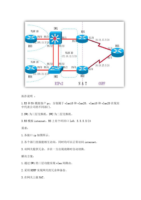
拓扑说明:1.R3和R4模拟客户pc,分别属于vlan10和vlan20。
vlan10和vlan20在现实中代表公司的不同部门。
2.SW1为三层交换机,SW2为二层交换机。
3.R5模拟internet,R5上有个环回口lo0:5.5.5.5/24需求:1.各接口ip如图所示。
2.各个部门直接能相互访问,同时均可以正常访问internet。
3.双网关提供冗余,并在一方出现故障时自动切换。
解决方案:1.通过SW1的三层功能实现vlan间路由。
2.采用HSRP实现网关的冗余和备份。
3.在网关上做NAT。
4.内网运行RIPv2,外部运行OSPF。
实现网络的全联通,并保证内部与外部的相对隔离。
配置摘要如下:R01#sh run!!interface FastEthernet0/0ip address 172.16.12.1 255.255.255.0ip rip advertise 5ip nat insideip virtual-reassemblyspeed 100full-duplexstandby 1 ip 172.16.12.254standby 1 priority 120standby 1 preemptstandby 1 track Serial1/0 100!!interface Serial1/0ip address 10.10.15.1 255.255.255.0ip nat outsideip virtual-reassemblyserial restart-delay 0no dce-terminal-timing-enable!!router ospf 100router-id 1.1.1.1log-adjacency-changesnetwork 10.10.15.1 0.0.0.0 area 0!router ripversion 2timers basic 5 15 0 15network 172.16.0.0no auto-summary!ip nat inside source list 1 interface Serial1/0 overload!access-list 1 permit 192.168.0.0 0.0.255.255!!!end///////////////////////////////////////////////////////////////////// //////////////////////R02#sh run!!interface FastEthernet0/0ip address 172.16.12.2 255.255.255.0ip rip advertise 5ip nat insideip virtual-reassemblyspeed 100full-duplexstandby 1 ip 172.16.12.254standby 1 preemptstandby 1 track Serial1/0!!interface Serial1/0ip address 10.10.25.2 255.255.255.0ip nat outsideip virtual-reassemblyserial restart-delay 0no dce-terminal-timing-enable!!router ospf 100router-id 2.2.2.2log-adjacency-changesnetwork 10.10.25.2 0.0.0.0 area 0!router ripversion 2timers basic 5 15 0 15network 172.16.0.0no auto-summary!!ip nat inside source list 1 interface Serial1/0 overload!access-list 1 permit 192.168.0.0 0.0.255.255!!end///////////////////////////////////////////////////////////////////// ////////////////R03#sh run!no ip routing!!interface FastEthernet0/0ip address 192.168.13.3 255.255.255.0no ip route-cachespeed 100full-duplex!!ip default-gateway 192.168.13.254!!end///////////////////////////////////////////////////////////////////// /////////////////R04#sh run!no ip routing!!!interface FastEthernet0/0ip address 192.168.24.4 255.255.255.0no ip route-cachespeed 100full-duplex!!ip default-gateway 192.168.24.254!end///////////////////////////////////////////////////////////////////// ///////////////////R05#sh run!!interfaceLoopback0 //模拟internet上的某个网络节点ip address 5.5.5.5 255.255.255.0ip ospf network point-to-point!!interface Serial1/0ip address 10.10.15.5 255.255.255.0serial restart-delay 0no dce-terminal-timing-enable!interface Serial1/1ip address 10.10.25.5 255.255.255.0serial restart-delay 0no dce-terminal-timing-enable!!router ospf 100router-id 5.5.5.5log-adjacency-changesnetwork 5.5.5.5 0.0.0.0 area 0network 10.10.15.5 0.0.0.0 area 0network 10.10.25.5 0.0.0.0 area 0!!end///////////////////////////////////////////////////////////////////// ///////////////////SW01#sh run!interface FastEthernet0/1switchport access vlan 30no ip addressduplex fullspeed 100!!interface FastEthernet0/3switchport access vlan 10no ip addressduplex fullspeed 100!!interface FastEthernet0/12switchport mode trunkno ip addressduplex fullspeed 100!interface FastEthernet0/13switchport mode trunkno ip addressduplex fullspeed 100!!!interface Vlan10ip address 192.168.13.254 255.255.255.0ip rip advertise 5!interface Vlan20ip address 192.168.24.254 255.255.255.0ip rip advertise 5!interface Vlan30 // vlan30的设置至关重要,它保证了内部客户机和网关之间ip address 172.16.12.123 255.255.255.0 // 的连通性。
CISCO HSRP工程实例

CISCO HSRP工程实例CISCO, HSRP, 实例, 工程下载 (100.5 KB)2007-6-9 19:57标记:接入层交换机我们标记为sw1,做热备的两台交换机,左边的我们标记为sw2,右边的标记为sw3。
说明:我这里的连线方式和拓扑上的不一样,具体方式如下:Switch1 F0/1 <----> Switch2 F0/1Switch1 F0/2 <----> Switch3 F0/2Switch2 F0/10 <----> Switch3 F0/10Switch2 F0/2 <----> Switch4 F0/2Switch3 F0/1 <----> Switch4 F0/1Router1 F0/0 <----> Switch4 F0/0本帖隐藏的内容需要回复才可以浏览router配置:Router#show runBuilding configuration...Current configuration : 1023 bytes!version 12.4service timestamps debug datetime msecservice timestamps log datetime msecno service password-encryption!hostname Router!boot-start-markerboot-end-marker!!no aaa new-modelmemory-size iomem 5!!ip cef!!!!!!!!!!!!!!!!!!!!!!interface FastEthernet0/0ip address 172.16.1.1 255.255.255.0 duplex autospeed auto!interface Serial1/0ip address 10.250.34.51 255.255.255.0 serial restart-delay 0!interface Serial1/1no ip addressshutdownserial restart-delay 0!interface Serial1/2no ip addressshutdownserial restart-delay 0!interface Serial1/3no ip addressshutdownserial restart-delay 0!ip http serverno ip http secure-server!ip route 0.0.0.0 0.0.0.0 Serial1/0 2ip route 192.168.10.0 255.255.255.0 172.16.1.2 ip route 192.168.10.0 255.255.255.0 172.16.1.3 ip route 192.168.20.0 255.255.255.0 172.16.1.3 ip route 192.168.20.0 255.255.255.0 172.16.1.2 !!!!control-plane!!!!!!!!!!line con 0line aux 0line vty 0 4login!!endsw1配置:sw1#show runBuilding configuration...Current configuration : 940 bytes!version 12.4service timestamps debug datetime msec service timestamps log datetime msec no service password-encryption!hostname sw1!boot-start-markerboot-end-marker!!no aaa new-modelmemory-size iomem 5!!ip cef!!!!!!!!!!!!!!!!!!!!!!interface FastEthernet0/0 !interface FastEthernet0/1 switchport mode trunk!interface FastEthernet0/2 switchport mode trunk!interface FastEthernet0/3 !interface FastEthernet0/4 !interface FastEthernet0/5 !interface FastEthernet0/6 !interface FastEthernet0/7 !interface FastEthernet0/8 !interface FastEthernet0/9 !interface FastEthernet0/10 !interface FastEthernet0/11 !interface FastEthernet0/12 !interface FastEthernet0/13 !interface FastEthernet0/14 !interface FastEthernet0/15 !interface Vlan1no ip address!ip http serverno ip http secure-server !!!!!control-plane!!!!!!!!!!line con 0line aux 0line vty 0 4login!!endsw2配置:sw2#show runBuilding configuration...Current configuration : 1497 bytes!version 12.4service timestamps debug datetime msec service timestamps log datetime msec no service password-encryption!hostname sw2!boot-start-markerboot-end-marker!!no aaa new-modelmemory-size iomem 5!!ip cef!!!!!!!!!!!!!!!!!!!!!!!!interface Port-channel1switchport mode trunk!interface FastEthernet0/0!interface FastEthernet0/1 switchport mode trunk!interface FastEthernet0/2no switchportip address 172.16.1.2 255.255.255.0 !interface FastEthernet0/3!interface FastEthernet0/4!interface FastEthernet0/5!interface FastEthernet0/6!interface FastEthernet0/7!interface FastEthernet0/8!interface FastEthernet0/9!interface FastEthernet0/10switchport mode trunkchannel-group 1 mode on!interface FastEthernet0/11switchport mode trunkchannel-group 1 mode on!interface FastEthernet0/12switchport mode trunkchannel-group 1 mode on!interface FastEthernet0/13!interface FastEthernet0/14!interface FastEthernet0/15!interface Vlan1no ip address!interface Vlan10ip address 192.168.10.254 255.255.255.0 standby 1 ip 192.168.10.250standby 1 timers 3 50standby 1 priority 200standby 1 preemptstandby 1 track FastEthernet0/2 150!interface Vlan20ip address 192.168.20.254 255.255.255.0 standby 2 ip 192.168.20.250standby 2 preemptstandby 2 track FastEthernet0/2!ip http serverno ip http secure-server!!!!!control-plane!!!!!!!!!!line con 0line aux 0line vty 0 4login!!endsw3配置:sw3#show runBuilding configuration...Current configuration : 1572 bytes!version 12.4service timestamps debug datetime msec service timestamps log datetime msec no service password-encryption!hostname sw3!boot-start-markerboot-end-marker!!no aaa new-model memory-size iomem 5!!ip cef!!!!!!!!!!!!!!!!!!!!!!!!interface Port-channel1switchport mode trunk!interface FastEthernet0/0!interface FastEthernet0/1no switchportip address 172.16.1.3 255.255.255.0 !interface FastEthernet0/2 switchport mode trunk!interface FastEthernet0/3!interface FastEthernet0/4!interface FastEthernet0/5!interface FastEthernet0/6!interface FastEthernet0/7!interface FastEthernet0/8!interface FastEthernet0/9!interface FastEthernet0/10 switchport mode trunkchannel-group 1 mode on!interface FastEthernet0/11 switchport mode trunkchannel-group 1 mode on!interface FastEthernet0/12 switchport mode trunkchannel-group 1 mode oninterface FastEthernet0/13!interface FastEthernet0/14!interface FastEthernet0/15!interface Vlan1no ip address!interface Vlan10ip address 192.168.10.253 255.255.255.0standby 1 ip 192.168.10.250standby 1 timers 3 50standby 1 preemptstandby 1 track FastEthernet0/1!interface Vlan20ip address 192.168.20.253 255.255.255.0standby 2 ip 192.168.20.250standby 2 priority 200standby 2 preemptstandby 2 track FastEthernet0/1 150!ip http serverno ip http secure-server!!!mac-address-table static 0000.0c07.ac02 interface FastEthernet0/10 vlan 20 !!control-plane!!!!!!!!!line con 0line aux 0line vty 0 4login!!endsw4我这里没有做任何配置,大家可以根据需要在上面作访问控制列表之类的配置,好了,配置过程中遇到了一些问题,不过最后都解决了,坚持就是胜利啊!。
双组热备份HSRP详细配置实例

双组热备份HSRP详细配置实例【技术要点】HSRP 实际上在局域网用得较多,由于局域网内大多使用三层交换机,所以这时HSRP 是在交换机上配置的。
热备份HSRP详细配置网络拓扑图热备份HSRP详细配置过程R1配置1.r1(config)#int f0/02.r1(config-if)#ip add 192.168.1.1 255.255.255.03.r1(config-if)#no shu4.r1(config-if)#int f1/05.r1(config-if)#ip add 192.168.2.1 255.255.255.06.r1(config-if)#no shu7.r1(config)#router rip8.r1(config-router)#network 192.168.1.09.r1(config-router)#network 192.168.2.010.r1(config)#int f0/011.r1(config-if)#standby 47 ip 192.168.1.25412.r1(config-if)#standby 47 priority 180 优先级为18013.r1(config-if)#standby 47 preemtp 配置占先权14.r1(config-if)#standby 47 track f1/0 100 端口跟踪,优先级减少10015.r1(config-if)#standby 100 ip 192.168.1.25316.r1(config-if)#standby 100 priority 150R2配置1.r2(config)#int f0/0r2(config-if)#ip add 192.168.1.2 255.255.255.02.r2(config-if)#no shu3.r2(config-if)#int f1/04.r2(config-if)#ip add 192.168.3.1 255.255.255.05.r2(config-if)#no shu6.r2(config)#router rip8.r2(config-router)#network 192.168.3.09.r2(config)#int f0/010.r2(config-if)#standby 47 ip 192.168.1.254 备份组为47虚拟IP为1.25411.r2(config-if)#standby 47 priority 150 优先级为15012.r2(config-if)#standby 100 ip 192.168.1.25313.r2(config-if)#standby 100 priority 18014.r2(config-if)#standby 100 preempt15.r2(config-if)#standby 100 track f1/0 100R3配置1.r3(config)#int f0/02.r3(config-if)#ip add 192.168.2.2 255.255.255.03.r3(config-if)#no shu4.r3(config-if)#int f1/05.r3(config-if)#ip add 192.168.3.2 255.255.255.06.r3(config-if)#no shu7.r3(config-if)#int f2/08.r3(config-if)#ip add 192.168.4.1 255.255.255.09.r3(config-if)#no shu10.r3(config)#router rip11.r3(config-router)#network 192.168.2.012.r3(config-router)#network 192.168.3.014.VPCS1:ip 192.168.1.3 192.168.1.254 24 VPCS1IP为1.3网关为1.25415.VPCS2:ip 192.168.4.2 192.168.4.1 24 VPCS2IP为4.2网关为4.1再查看:R1#sh standbyFastEthernet0/0 - Group 47State is Active2 state changes, last state change 00:04:50Virtual IP address is 192.168.1.254Active virtual MAC address is 0000.0c07.ac2fLocal virtual MAC address is 0000.0c07.ac2f (v1 default)Hello time 3 sec, hold time 10 secNext hello sent in 0.800 secsPreemption enabledActive router is localStandby router is 192.168.1.2, priority 150 (expires in 8.776 sec)Priority 180 (configured 180)Track interface FastEthernet1/0 state Up decrement 100IP redundancy name is "hsrp-Fa0/0-47" (default)FastEthernet0/0 - Group 100State is Standby4 state changes, last state change 00:01:37Virtual IP address is 192.168.1.253Active virtual MAC address is 0000.0c07.ac64Local virtual MAC address is 0000.0c07.ac64 (v1 default)Hello time 3 sec, hold time 10 secNext hello sent in 1.824 secsPreemption disabledActive router is 192.168.1.2, priority 180 (expires in 7.092 sec)Standby router is localPriority 150 (configured 150)IP redundancy name is "hsrp-Fa0/0-100" (default)R2#sh standby briP indicates configured to preempt.|Interface Grp Prio P State Active Standby Virtual IPFa0/0 47 150 Standby 192.168.1.1 local 192.168.1.254Fa0/0 100 180 P Active local 192.168.1.1 192.168.1.253总结:1)配置多个HSRP组:之前的步骤已经虚拟了192.168.1.254网关,对于这个网关只能有一个活动路由器,于是这个路由器将承担全部的数据流量。
思科 HSRP的配置方案双机热备经典案例.

提问"当主用路由器当掉以后备份路由器可以接管主用路由器的IP地址和M AC地址回答Router1:Router1#configure terminalRouter1(config)#interface FastEthernet 0/1Router1(config-if)#ip address 172.22.1.3 255.255.255.0Router1(config-if)#standby 1 ip 172.22.1.1Router1(config-if)#standby 1 priority 120Router1(config-if)#exitRouter1(config)#endRouter1#Router2:Router2#configure terminalRouter2(config)#interface FastEthernet 1/0Router2(config-if)#ip address 172.22.1.2 255.255.255.0Router2(config-if)#standby 1 ip 172.22.1.1Router2(config-if)#standby 1 priority 110 (默认priority is 100) Router2(config-if)#exitRouter2(config)#endRouter2# 注释由于HSRP虚拟出来的MAC地址跟组相关,所以可能会出现同一交换机收到多个相同的MAC地址的情况,这时候就需要用standby 1 mac-addres s 0000.0c07.ad01 命令来人工指定一个MAC地址提问强制某个路由器启动后一直在组中处于主用状态回答Router1#configure terminalRouter1(config)#interface FastEthernet 0/1Router1(config-if)#standby 1 ip 172.22.1.1Router1(config-if)#standby 1 priority 120Router1(config-if)#standby 1 preemptRouter1(config-if)#exitRouter1(config)#endRouter1#Router2#configure terminalRouter2(config)#interface FastEthernet 1/0Router2(config-if)#standby 1 ip 172.22.1.1Router2(config-if)#standby 1 priority 110Router2(config-if)#standby 1 preempt delay 60 (最好有时延) Router2(config-if)#exitRouter2(config)#end注释正常情况下当LAN端口up后就会发生强占,而此时可能网络还没有收敛,所以建议配置强占延迟时间,让路由器启动后过一段时间再发起强占standby 1 preempt delay 6022.3. 配置HSRP对接口问题追踪的支持提问当主用路由器的上联端口出现问题后主动切换到备用路由器回答Router1#configure terminalRouter1(config)#interface FastEthernet0/1Router1(config-if)#standby 1 ip 172.22.1.1Router1(config-if)#standby 1 priority 120Router1(config-if)#standby 1 preemptRouter1(config-if)#standby 1 track Serial0/0 20Router1(config-if)#exitRouter1(config)#end从12.2(15)T后引入更多可追踪实例Router1#configure terminalRouter1(config)#track 11 interface Serial1/1 ip routing Router1(config-track)#exitRouter1(config)#interface FastEthernet0/0Router1(config-if)#standby 1 ip 172.22.1.1Router1(config-if)#standby 1 priority 120Router1(config-if)#standby 1 preemptRouter1(config-if)#standby 1 track 11 decrement 50 Router1(config-if)#end注释Router1#show trackTrack 11Interface Serial1/1 ip routingIP routing is Down (hw admin-down, ip disabled)1 change, last change 00:12:48Tracked by:HSRP FastEthernet0/0 122.4. HSRP负载均衡提问在两台或者多台HSRP路由器上实现流量的负载均衡回答Router1#configure terminalRouter1(config)#interface FastEthernet0/1Router1(config-if)#ip address 172.22.1.3 255.255.255.0 Router1(config-if)#standby 1 ip 172.22.1.1Router1(config-if)#standby 1 priority 120Router1(config-if)#standby 1 preemptRouter1(config-if)#standby 2 ip 172.22.1.2Router1(config-if)#standby 2 priority 110Router1(config-if)#standby 2 preemptRouter1(config-if)#exitRouter1(config)#endRouter2#configure terminalRouter2(config)#interface FastEthernet1/0Router2(config-if)#ip address 172.22.1.4 255.255.255.0 Router2(config-if)#standby 1 ip 172.22.1.1Router2(config-if)#standby 1 priority 110Router2(config-if)#standby 1 preemptRouter2(config-if)#standby 2 ip 172.22.1.2Router2(config-if)#standby 2 priority 120Router2(config-if)#standby 2 preemptRouter2(config-if)#exitRouter2(config)#end注释由于出现两个网关,所以需要在终端设备上分开配置各自的缺省网关。
- 1、下载文档前请自行甄别文档内容的完整性,平台不提供额外的编辑、内容补充、找答案等附加服务。
- 2、"仅部分预览"的文档,不可在线预览部分如存在完整性等问题,可反馈申请退款(可完整预览的文档不适用该条件!)。
- 3、如文档侵犯您的权益,请联系客服反馈,我们会尽快为您处理(人工客服工作时间:9:00-18:30)。
HSRP配置实例1 HSRP协议原理产生背景随着Internet的日益普及,人们对网络的依赖性也越来越强。
这对网络的稳定性提出了更高的要求,人们自然想到了基于设备的备份结构,就像在服务器中为提高数据的安全性而采用双硬盘结构一样。
网络核心层设备是整个网络的心脏,如果设备发生致命性的故障,将导致本地网络的瘫痪,如果是骨干路由器,影响的范围将更大,所造成的损失也是难以估计的。
因此,对核心设备采用热备份是提高网络可靠性的必然选择。
在一个核心设备完全不能工作的情况下,它的全部功能便被系统中的另一个备份设备完全接管,直至出现问题的设备恢复正常,这就是热备份路由协议HSRP(Hot Standby Router Protocal)要解决的问题。
HSRP原理HSRP是Cisco公司制定的专有路由器备份协议,支持多台路由器形成热备而消除单台设备失效造成的网络中断。
实现HSRP的条件是系统中有2台以上的路由器组成一个“热备份组”,这个组形成一个虚拟路由器。
HSRP协议利用一个优先级(priority)方案来决定哪台配置了HSRP协议的路由器成为活跃路由器(active router)。
用户可以手动设置HSRP优先级的值。
如果一个路由器的优先级设置的比所有其他路由器的优先级高,则该路由器成为相应备份组的活跃路由器。
当在预先设定的一段时间(Hold Time)内,不能收到活跃路由器发送的hello消息时,优先级最高的备用路由器变为活跃路由器。
网络上的所有主机不感知路由器之间的报文交互。
其协议基本原理与VRRP类似,如下图所示。
图1-1 HSRP协议基本原理示意图基本概念备份组:组成虚拟路由器的一组设备,称为HSRP路由器;活跃路由器(active router):备份组中代表虚拟路由器转发数据包的路由器;备份路由器(standby router):备份组中第一备份路由器;Hello Time:设备发送Hello报文的时间间隔,如果未配置Hello Time值,则根据活跃路由器成功发送两个hello消息的时间间隔来确定,否则使用缺省值3秒;Hold Time:HSRP路由器在声明活跃路由器发生故障之前等待的时间,最少为Hello time 的3倍;备份优先级:路由器在HSRP备份组内的级别,缺省为100。
如果优先级相同,那么由IP地址最大的路由器成为活跃路由器,此地址为配置HSRP接口的IP地址。
虚拟MAC地址:由三部分组成的虚拟路由器使用的MAC地址以00.00.0c.07.ac.2f为例,厂商ID:前三个字节是厂商ID,00.00.0c是Cisco设备。
HSRP编码:用来说明本MAC地址是用于标识一台HSRP虚拟路由器的,总是07.ac。
HSRP组号:即组ID,标识HSRP备份组的编号。
本例中2f为十六进制,转换为十进制为47。
HSRP消息配置了HSRP协议的路由器存在以下三种多点广播消息:Hello:发送该消息表明路由器正在运行HSRP,并且能够成为活跃路由器或者备份路由器。
HSRP路由器默认每3秒钟发送一个Hello消息;Coup:当一个备份路由器变为一个活跃路由器时发送一个Coup消息;Resign:当活跃路由器要宕机或者当有优先级更高的路由器发送hello消息时,活跃路由器发送resign消息,表明不想再当活跃路由器;HSRP消息被封装在UDP报文中,使用UDP端口号1985,目的地址是全部路由器(all-router)多点广播地址224.0.0.2,TTL值为1。
HSRP状态HSRP定义了配置HSRP功能的路由器中可能有的6种状态:初始状态(Initial):HSRP启动时的状态,此时HSRP还没有运行,一般是在改变配置或端口刚刚启动时进入该状态。
学习状态(Learn):路由器等待来自活跃路由器的消息。
这时,路由器还没有看到来自活跃路由器的Hello消息,也没有学到虚拟路由器的IP地址。
倾听状态(Listen):路由器正在监听Hello消息。
已经知道了虚拟IP地址,除了活跃和备份路由器之外的其他路由器都保持倾听状态。
发言状态(Speak):在该状态下,路由器发送周期性Hello消息,并参与活跃路由器或备份路由器的竞选。
备份状态(Standby):备份组内路由器所处的状态,备份组员监视活跃路由器,随时准备在活跃路由故障时,接替其数据传输功能。
周期性的发送Hello消息,向其他组员通告自己的状态。
活跃状态(Active):备份组内活跃路由器的状态,负责数据传输功能。
2 互通性分析从“HSRP协议原理”章节可以看出,HSRP报文的目的MAC与VRRP完全不同,可见两种协议无法对接。
因此,华为S系列交换机替换思科设备时,只能选择使用VRRP协议替换HSRP 协议,替换思路有如下两种:割接前将Cisco设备HSRP整改为VRRPa.将HSRP备设备三层接口shutdown,此时下行业务会部分受影响,断流时间为路由切换时间;b.将HSRP备设备配置整改为VRRP主设备,保持三层接口down;c.将HSRP主设备三层接口shutdown,然后打开VRRP备设备的三层接口,完成业务切换;d.将HSRP主设备整改为VRRP备设备,打开三层接口,HSRP切换VRRP完成;e.将VRRP备设备的业务割接至华为VRRP备设备;f.将VRRP主设备的业务割接至华为VRRP主设备。
直接将HSRP下行主备链路同时割接至华为VRRP主备设备a.割接前保证华为设备有网络侧路由,以使业务平台割接至华为设备后业务损失降到最低;b.将HSRP备设备下行接口shutdown,将物理线缆割接是VRRP主设备,保持端口down;c.将HSRP主设备下行接口shutdown,随即打开VRRP主设备端口,业务完成切换;d.将原互连HSRP主设备的物理线缆割接至VRRP备设备,打开VRRP备设备端口,割接完成。
实际上第一种整改方式不常用,因为在第3步切换的时候,会有约3秒左右业务中断,因此通常直接选择将HSRP主备下行端口同时割接至华为的VRRP主备下行端口。
3 实现对比协议对比表3-1 HSRP与VRRP协议对比命令对比表3-2 HSRP与VRRP命令对比4 对接替换方案简介HSRP与VRRP协议无法实现对接,因此替换方案为将HSRP下行主备链路同时割接至华为VRRP主备设备。
组网需求如图4-1所示,组网中均为思科交换机。
两台核心交换机采用堆叠方式。
两台汇聚交换机之间使用手工模式的Eth-trunk进行链路冗余备份,上行通过配置OSPF与核心交换机建立OSPF邻居关系收发路由,下行通过配置HSRP实现虚拟网关备份,其中CiscoA为主用网关设备,CiscoB为备用网关设备。
组网中交换机通过Rapid PVST 进行破环操作。
现根据需要,使用华为S系列交换机替换组网中的两台汇聚交换机,且不改变原网络规划。
思科汇聚设备HSRP相关配置如下:CiscoAinterface Vlan110ip address 172.31.217.156 255.255.255.224standby 110 ip 172.31.217.158standby 110 priority 110standby 110 preempt delay minimum 60standby 110 authentication hsrp110interface Vlan120ip address 172.31.218.157 255.255.255.224standby 120 ip 172.31.218.158standby 120 authentication hsrp120CiscoBinterface Vlan110ip address 172.31.217.155 255.255.255.224standby 110 ip 172.31.217.158standby 110 authentication hsrp110interface Vlan120ip address 172.31.218.156 255.255.255.224standby 120 ip 172.31.218.158standby 120 priority 110standby 120 preempt delay minimum 60standby 120 authentication hsrp120图4-1 HSRP组网图配置思路采用如下配置思路:1.配置华为S系列交换机的OSPF功能,实现与上行核心交换机建立OSPF邻居关系收发路由。
2.通过手工模式配置华为S系列交换机之间的链路聚合,实现负载分担。
3.配置华为S系列交换机的VRRP功能替换原思科交换机HSRP,实现虚拟网关备份。
4.配置华为S系列交换机,实现与网络中其他思科交换机的环网互通,实现破坏。
具体对接方案参见思科生成树协议和华为生成树协议对接/替换指导5.依据原网络规划,配置华为S系列交换机相关业务转发功能。
操作步骤步骤 1通过show standby brief命令查看设备的主备状态。
# 查看CiscoA设备的HSRP主备状态。
CiscoA# show standby briefP indicates configured to preempt.Interface Grp Pri PState Active Standby Virtual IPVlan110 110 110 PActive local 172.31.217.155 172.31.217.158Vlan120 120 100 Standby172.31.218.156 local 172.31.218.158# 查看CiscoB设备的HSRP主备状态。
CiscoB# show standby briefP indicates configured to preempt.|Interface Grp Pri PState Active Standby Virtual IPVlan110 110 100 Standby172.31.217.156 local 172.31.217.158Vlan120 120 110 PActive local 172.31.218.157 172.31.218.158 步骤 2 将两台华为S系列交换机上电并通过旁挂的方式连接之间链路及上行链路。
核心交换机新增下行接口地址,华为S系列交换机新增上行接口地址及loopback地址,配置VRRP功能,其中HuaweiB配置为Master设备。
完成华为S系列交换机所有配置,并将下行链路接入侧的VLANIF接口shutdown。
# 配置HuaweiB的VRRP功能,配置其为VRRP备份组1的的Master设备,备份组2的Backup设备。