GS温泉操作说明书
海洛斯操作手册(说明书)
HIROSS恒温恒湿机房精密空调操作手册HIMOD系列北京****科技有限公司技术部2009年01月01日目录第一章HIMOD系列海洛斯空调概述 (2)型号多 (3)控制技术先进 (3)制冷系统 (3)送风系统 (3)加湿系统 (3)加热系统 (4)1.7其它 (4)第二章HIMOD系列海洛斯空调型号含义 (4)第三章有关空调的一些资料 (5)气流组织方式(详见下图) (5)盖板纽开启方式(详见下图) (5)空调重量(单位:Kg) (5)机组尺寸及维护空间 (6)第四章制冷循环管路示意图 (7)风冷却(A型) (7)水冷却(W型) (8)双冷源(D型) (9)单系统(C型) (10)双系统(C型) (10)第五章调速风机调速接线示意图 (11)第六章MICROF ACE概述 (12)概述 (12)面板简介液晶显示屏 (13)液晶显示屏介绍 (13)第七章MICROF ACE面板的操作 (13)第八章控制器的使用 (14)控制器(HIROMATIC)概述 (14)控制器的操作 (15)菜单结构 (17)第九章日常维护及特殊维护 (18)日常维护 (18)特殊维护 (19)第十章常见报警及处理 (20)低压报警 (20)高压报警 (21)加湿报警 (21)失风报警 (21)电加热过热报警 (22)显示器发黑 (22)空调不制冷 (22)附录1:参数列表 (22)附录2:报警内容列表 (26)附录3:各菜单项含义: (28)第一章HIMOD系列海洛斯空调概述HIMOD系列海洛斯空调(HIMOD空调)是当今世界上最先进的机房专用恒温恒湿机房专用精密空调。
随着IT业的突飞猛进的发展,各种布局、面积差别很大的机房如雨后春笋般纷纷出现了,使用环境也不一而同。
为适应各种不同要求的机房,新开发的海洛斯HIMOD系列空调应运而生。
她是在保留她的前一代产品HIRANGE系列机房空调的优点,又应用了当今世界上提高了的制冷技术及制冷部件制造工艺,使用当今最先进的模块化设计理念生产出来的高科技机房空调产品。
98005C 冷水泉缸 FLEXI-GUARD 安装、维护与使用指南说明书

98005C (REV. B - 3/05)1SWIRLFLO Refrigerated fountains with FLEXI-GUARDINSTALLATION, CARE & USE MANUALT MT MENOB2-8C ENOB2-8RACfor future reference.NOTE:It is common practice to ground electrical hardware such as telephones, computers and other devices toavailable water lines. This can, however, cause electrical feedback in the plumbing circuit, which results in an “electrolysis” effect occurring in the fountain. This may result in water which has a metallic taste to it or has a noticeable increase in the metallic content of the water.When inspecting plumbing circuit, remember the line may be grounded some distance from the installation,and may occur outside the building or area in which the unit is being installed.This condition can be avoided (in most cases) by using recommended materials during installation. Any drain fittings provided by the installer should be made of plastic which will electronically isolatethe fountainfrom the remainder of the building’s plumbing circuits.A B DL98005C (REV. B - 3/05)298005C (REV. B - 3/05)31. Install chiller: Remove front panel of chiller. Slide chiller onto the shelf and position it to the left as per dimensions in Figure 1.Note: Building construction must allow foradequate air flow on both sides, top and back of chiller. A minimum of 4” (102mm) on both sides and top is required. See chiller installation for additional instructions.2. Attach solenoid valve assembly to the underside of cross member of mounting frame on electronic sensor unit. (See Fig. 7).3.Make water supply connections. Inlet port is marked on the chiller (1/4” O.D. copper tube). Bend the copper tube (provided) at an appropriate length from the chiller toopening in frame. Install the in-line strainer (provided with chiller) by pushing it in until it reaches a positive stop,approximately 3/4” (19mm) on the marked chiller inlet port (See Figs. 3) (Refer to Fig. 13 on page 7 for details on assembling quick connect fittings). Attach an unplated and deburred copper water inlet line and a service stop (not provided) to the chiller. Turn on the water supply and flush the line thoroughly.Caution: DO NOT SOLDER tubes insertedinto the strainer as damage to o-rings may result.4.Make connection between remote chiller outlet tube and solenoid valve assembly. Outlet port is marked on the chiller (1/4” O.D. copper tube). Install a 1/4” tee(provided) on the marked chiller outlet port. Insert one end of 1/4” poly tubing into the tee and the other end into the straight fitting on the solenoid valve assy. (See Fig. 3)5. Hang the upper panel on the mounting frame hanger. Be sure that the panel is engaged with hanger at the top of frame before releasing it. Align holes in the panel with holes in the mounting frame. Install two (2) #10-24 x 5/8” (16mm) screws (Item 27 - Figure 4) in holes and tighten securely.6. Install the fountain. Remove the screw (Item 28) from cover plate (Item 12) and slide cover plate toward basin. Mount the fountain to the upper panel and frame with (4) 5/16” x 1” (25mm) long bolts (Item 30), bracket (Item 34) and nuts (Item 33) provided. Tighten securely. Brackets (Item 34) must be installed as shown to properly support fountain. (See Fig. 5)Special ToolsItemDescription QuantityNONEAdditional MaterialsI tem DescriptionQuantity1Unplated copper inlet pipe 2Service StopREQUIRED TOOLS AND MATERIALSThese tables show special tools and/oradditional materials (not provided) which are necessary to complete installation of these units:Figure 2 - Chiller InstallationCHILLER INLETCHILLER OUTLET222123TO BUBBLER21Figure 3 - ENO Tube Routing98005C (REV. B - 3/05)4Figure 4 - Upper Panel InstallationFigure 5 - Fountain InstallationFigure 6 - Lower Panel Installation7. Attach waste tube (1-1/4” O.D.) to 1-1/4” O.D. slip trap (provided by others).8.Connect the fountain drain waste tube to the building sanitary sewer system. Connection should be made in compliance with local plumbing code requirements. (Note:Plumbing trap is not included with the fountain).9.Make connection between solenoid valve assembly and fountain(s). Insert the 1/4” poly tubing coming from the fountain with sensor into the solenoid valve. Insert the 1/4”poly tubing coming from the fountain with push button into the tee (See Fig. 3).10.Connect power cord of sensor to solenoid valveassembly by running it through the back panel and connecting it to terminal as shown in Fig. 8.11.Turn on water supply and check for leaks. Release airfrom tank by interrupting infrared beam; a steady stream of water assures all air is removed. The sensor has a 30 second maximum ON time. It may be necessary to step away from beam a few times to allow chiller tank to fill.DO NOT SOLDER tubes whileinserted into the strainer as damage to o-rings may result.12.These products are designed to operate on 20-105PSIG supply line pressure. If inlet pressure is above 105PSIG, a pressure regulator must be installed in the supply line.Any damage caused byconnecting these products to a supply line with pressure lower than 20 PSIG orhigher than 105 PSIG IS NOT covered under warran ty.13.Make electrical connections to the chiller. See chillerinstructions.14. Check stream height from bubbler. Stream height isfactory set at 35-40 PSI. If supply pressure varies greatly from this, please do the following. For Push Button units only , remove push button (Item 14 - Figure 12) and adjust thescrew on the regulator (Item 16 - Figure 12). To remove push button, remove set screw from bottom ofsleeve (Item 31). Insert a small punch in screw hole and push up while grasping the push button and pull forward removing the push button. Clockwise adjustment will raise stream height and counterclockwise movement will lower stream height. For best adjustment streamshould hit basin approximately 6-1/2” from the bubbler.Reassemble push button by pushing in on button until the push button catches in the sleeve. Reinstall the set screw (Item 31) in the sleeve (Item 12).For Electronic sensor units only , remove lowerpanel (Item 26 - Fig. 4) and turn adjustment screw on the regulator (Item 16 - Fig. 8). Clockwise adjustment will raise stream height and counterclockwise movement will lower stream height. For best adjustment stream should hit basin approximately 6-1/2” from the bubbler.15. Mount lower panel. Loosen the three (3) #10-24 x 5/8” (16mm) screws (Item 27 - Figure 5) at frame bottom lip. Slide upper tongue of lower panel (Item 26 - Figure 6) under lower edge of already installed upper panel. Tighten previously loosened screws securely. (See Figure 6)30282724, 2527263433View From Rear1198005C (REV. B - 3/05)5163915413445, 46, 4729384048ENOB2-8CFigure 8 - Regulator AssemblyFigure 7 - Solenoid AssemblyENOB2-8RAC29347CONNECT TO FOUNTAIN SENSOR WIRING CONNECTOR98005C (REV. B - 3/05)6See Fig. 1020BUBBLER DETAILNOTE:When installing replacement bubbler and pedestal,tighten nut (Item 5) only to hold parts snug in position. Do Not Overtighten.Basin12345321981811910353743424427366Figure 9 - Exploded ViewFigure 10 - Bubbler Assembly98005C (REV. B - 3/05)7Figure 11 - Fountain Body AssemblyFigure 12 - Push Button Assembly121314151617313220See Fig. 10818See Fig. 10921291019271132Figure 14 – Water Supply ConnectionsDIRECTION (NOT FURNISHED)3/8" O.D. UNPLATED COPPER TUBE CONNECT 1/4" O.D. TUBE Figure 13 – Quick Connect FittingsActuation of Quick Connect Water Fittings: Cooler is provided with lead-free connectors which utilize an o-ring water seal. To remove tubing from the fitting, relieve water pressure, push in on the gray collar while pulling on the tubing. (See Figure 13) To insert tubing, push tube straight into fitting until it reaches a positive stop (approximately 3/4”).49PARTS LISTITEM NO.PART NO.DESCRIPTION1 2 3 4 5 6 7 8 9 10 11 12 13 14 15 16 17 18 19 20 21 22 23 24 25 26 27 28 29 30 31 32 33 34 35 36 37 38 39 40 41 42 43 44 45 46 47 48 4956073C40322C56011C55997C75580C15027C28455C28474C28473C45767C28343C45781C45847C45848C50986C61315C15005C56163C45769C45768C56092C70682C55996C28383C28384C27026C11100834389070432C3841700175560C75632C70817C70020C28395C36207C36193C45813C31376C40045C50203C56082C56204C70022C70644C31272C70817C75507C28454C75671CBubbler AssyOrifice AssyHousing AssemblyPedestalBubbler LocknutBrkt - SwirlflowAssy - Brkt Solenoid/Reg/WireBasin - SwirlflowLower ShellFountain BodyCover PlateSleevePin - Push ButtonPush ButtonHolder - RegulatorRegulatorRetaining NutGasket - DrainAssy - Drain/TailpipeDrain - FerrulePoly Tubing (Cut To Length)Tee - 1/4Strainer (Provided with Chiller)Back Panel RH ADABack Panel LH ADALower PanelScrew - #10-24 x .62 HHSMScrew - #8-32 x .38 THSMScrew - #8-18 x .37 HHSMScrew - 5/16-18 x 1.00 HHMSSetscrew - #10-32 x .31Fttng - Elbow 1/4 x 1/4Nut - Hex 5/16-18Bracket - SupportWire - ExtensionAssy - Sensor EyeSleeve - Swirlflow EECord - Power 115vNut - Hex 1 5/16Bushing - Strain ReliefNut - RegulatorLens - Swirlflow EEScrew - #6-32 x .31 SetScrew - #6-32 x .50 PHMSSolenoid ValveFttng-Elbow 1/4 Stem x 1/4x90Fttng-1/4 NPTF x 1/4ODBrkt -Solenoid/Reg SwirlfloSpring - Push ButtonInstallation PackageThe components for installation are packed in threeseparate boxes, regardless of the type of unit beinginstalled. The boxes contain the following:Box No. 1: Wall Frame(s)Box No. 2: Remote Chiller, ECH8Box No. 3: Fountain Arm and PanelsAdditional materials, as noted in the Parts List, are alsoshipped in these boxes.1. Orifice Assy: Minerals deposits on orifice can cause water flow tospurt or not regulate. Mineral deposits may be removedfrom the orifice with a small round file not over 1/8" diameter or asmall diameter wire. CAUTION: Do not file or cut orifice materials.2. Stream Regulator: If orifice is free of material deposits regulatewater flow according to instructions on page 4.3. Sensor Control: The sensor has a 2 second delay time. If sensorfails to operate valve mechanism or operates erratically, checkthe following:a) Ensure there are no obstructions within a 40 inch radius fromthe front of fountain.b) Check wire connections at the solenoid valve and at the sensor.CAUTION: Make sure unit is unplugged before checking anywiring.c) Ensure proper operation of solenoid valve. If there is an audibleclicking sound yet no water flows, look for an obstruction in thevalve itself or elsewhere in the water supply line.WARNING: Do not expose sensor to direct sunlight.4. Sensor Range Adjustment: The electronic sensor used in thisfountain is factory pre-set for a "visual" range of 36 inches. Ifactual range varies greatly from this, or a different setting is desired,follow the range adjustment procedure below:a) Remove front lens.b) Locate range adjustment screw between the lenses of thesensor, then with a small tip screwdriver, rotate the range adjust-ing screw clockwise to increase range or counter-clockwise todecrease range. 1/4 turn of screw is equal to approximately12 - 18 inches of range.CAUTION: Complete range of sensor (24 - 46 inches) is only oneturn of the adjusting screw.c) Replace lens.TROUBLE SHOOTING AND MAINTENANCECARE AND CLEANING INSTRUCTIONSDO NOT use abrasive or chemical cleaners to clean the sensor lens.They may dull the luster and attack the plastic cover and chromefinish of the fountain. Use ONLY soap and water, then wipe withclean cloth or towel. When cleaning adjacent surfaces, the fountainand the sensor lens should be protected from any splattering ofcleaners. Acid and cleaning fluids can discolor and damage chromeplating and plastic sensor lens. 800-518-538898005C (REV. B - 3/05)8。
潜水池和温泉泳池泵所有者指南说明书

OWNER’S MANUAL Swimming Pool and Spa PumpREAD THIS MANUAL CAREFULLYBEFORE USING THE SPECK PUMPSECTION 1 IMPORTANT SAFETY INSTRUCTIONSWhen installing and using this electrical equipment,basic safety precautions should always be followed:READ AND FOLLOW ALL INSTRUCTIONS.WARNING -To reduce the risk of injury, do not permit children to use this equipment.(For cord - and plug - connected units)WARNING - Risk of Electric Shock. Connect onlyto a grounding type receptacle protected by a ground-fault circuit-interrupter (GFCI). Contact a qualified electrician if you cannot verify that the receptacle is protected by a GFCI.(For cord - and plug - connected units)WARNING - Do not bury cord. Locate cord to minimize abuse from lawn mowers, hedge trimmers,and other equipment.(For cord - and plug - connected units)WARNING - To reduce the risk of electric shock,replace damaged cord immediately.(For cord - and plug - connected units)WARNING - To reduce the risk of electric shock, do not use extension cord to connect unit to electric supply;provide a properly located outlet.(For swimming pool pumps with a minimum 25-foot(7.6-m) cord)NOTE: All wiring should be done by a qualified electrician in accordance with the National Electrical Code and all Local Codes.NOTE: Before installation, inspect all equipment, plumbing and wiring for damage that may have occurred during shipment.The shipping container has been specifically designed to prevent damage, however, any indications of damage should be carefully noted on the delivery ticket and a claim needs to be filed with the carrier.All pumps are water tested on a test stand to ensure that they meet specification.CAUTION - This pump is for use with storable pools only. Do not use with permanently installed pools. A storable pool is constructed so that it may be readily disassembled for storage and reassembled to its original integrity. A permanently installed pool is constructed in or on the ground or in a building such that it cannot be readily disassembled for storage.(For swimming pool pumps with or without a maximum 3 foot (0.91 -m) cord)CAUTION - This pump is for use with permanently installed pools and may also be used with hot tubs and spas if so marked. Do not use with storable pools. A permanently installed pool is constructed in or on the ground or in a building such that it cannot be readily disassembled for storage. A storable pool is constructed so that it may be readily disassembled for storage and reassembled to its original integrity.TO REDUCE RISK OF ELECTRICAL SHOCK,connect ground wires to grounding screw located in the motor. Use no smaller than a #1 2 AWG (3.3mm2) wire.TO REDUCE RISK OF ELECTRICAL SHOCK,a bonding connector is provided for bonding to metal water pipes, metal rails, or other metal within 5 feet of the swimming pool. All local points should be bonded with a #8 AWG (8.4mm2) wire.NOTE:To installer and/or operator of the Speck Swimming Pool Pump; the manufacturer’s warranty will be void if the pump is improperly installed and/or operated.READ INSTRUCTIONS CAREFULLY .SAVE THESE INSTRUCTIONS!1.2.3.4.5.6.7.8.9.10.SECTION 2 WINTERIZINGIn areas subject to freezing winter temperatures, protect by removing drain plugs. Do not replace plug.Store plug in strainer basket for winter.An alternative is to remove the pump and motor from plumbing and store indoors in a warm and dry location.Locate pump as close to the pool as practical.Consult local codes for minimum distance between pool and pump.The piping should be as direct and free from turns orbends as possible, as elbows and other fittings greatly increase friction losses.Place pump on a solid foundation which provides arigid and vibration-free support so that it is readily accessible for service and maintenance.Protect the pump against flooding and excessmoisture, and prevent foreign objects from clogging air circulation around motor.DO NOT store or use gasoline or other flammablevapors or liquids in the vicinity of this pump. DO NOT store pool chemicals near the pump.DO NOT remove any safety alert labels such asDANGER,WARNING,or CAUTION.Keep safety labels in good condition and replace missing or damaged labels.When connecting pipework to pump it is recommendedto use multi-purpose PVC glue to attach slip fittings to adaptors. If threaded connections are used it is recommended that thread seal tape be used. If the suction pipe is not sealed correctly, the pump will not prime properly and will pump small volumes of water or none at all. NOTE: The adaptors on the pump housing are factory mounted and should never be removed. Removal of these adaptors will void warranty.When installing the pump, care should be taken to seethat the suction line is below water level to a point immediately beneath the pump to ensure quick priming via a flooded suction line. The height between the pump and the water level should not be more that 4 feet. (Does not apply to Model 2180/..G for flooded suction.)SECTION 3EQUIPMENT OPERATION ANDMAINTENANCESECTION 4 MAINTENANCE2/1 LOCATION2/2 INSTALLATION1.2.3.4.5.6.1.2. 3.4.5.6.The pump requires little or no service other than reasonable care and periodic cleaning of the strainer basket. The seal on the pump is a mechanical seal.The seal may come loose during the course of time,depending on the running time and water quality. If water continually leaks out, a new mechanical seal should be fitted.To replace a mechanical seal, remove the eight bolts holding the casing to the seal-housing. Slide the motor part including the seal-housing out. Remove impellernut by turning it counter-clockwise when facing it,while holding motor shaft with a 1/2” wrench at rear end of motor. Pull pump impeller from shaft and slide seal from impeller shaft. To re-assemble,reverse the process. (Use a drop of loctite to secure the impeller nut.) Note: Make sure both parts of the mechanical seal (ceramic and spring portion) are clean. Gently wipe polished faces with soft and dry cotton cloth.Surfaces can easily be damaged by dirt and scratching.Only water should be used as lubricant to mount both parts of the mechanical seal.REV. 071503 - Model 21 - 802999999926Suction and discharge line should be independentlysupported at a point near the pump to avoid strains being placed on the pump.It is advisable to install a gate valve and union in boththe suction and discharge line in the event that the pump must be removed for servicing.Model GSBefore starting the pump for the first time, remove the filler plug. Fill pump body with water until level with suction inlet. Replace plug, hand tight, making sure the O-ring is not damaged. (Does not apply to Model 2180/..G for flooded suction.)Model BSBefore starting the pump for the first time, remove the see-through lid. (Unscrew each of the four lid-knobs a little at a time, and continue this process until the whole lid comes off evenly, not tilted .) Fill strainer tank with water until level with suction inlet. Replace lid, making sure the O-ring is not damaged. Screw the four lid-knobs down evenly, hand tight.When installing and using the motor, basic safetyprecautions should always be followed. The wiring of motor should be done by a licensed electrician in accordance with local codes. Be certain that the motor frame is grounded. Motor name plate has voltage, phase, ampere draw and other motor information as well as wiring connection instructions.BONDING:As required by National Electrical Code Article 690-22, the pump motor must be electrically bonded to the pool structure (reinforced bars, etc.) by a solid copper conductor not smaller than #8 AWG via the external copper bonding lug on the pump motor.GROUNDING:Permanently ground the pump motor using a conductor of appropriate size. Connect to the #10 green headed ground screw provided inside the motor terminal box.NOTE:Do not connect to electric power supply until unit is permanently grounded.Make sure see-through lid and o-ring are clean and properly positioned. Tighten see-through lid (hand tight). Tighten all pipes and fittings on suction side of pump.Be sure water in pool is high enough to flow through skimmer.Make sure strainer tank is full of water.Open all valves in system. Clean skimmer and strainer tank. Open pump and check for clogging of impeller.Check voltage at motor. If low, pump will not come up to speed.Check that all power switches are on. Be sure fuse or circuit breaker is properly set.Time set properly? Check motor wiring at terminals.With power off, turn shaft. It should spin freely. If not, disassemble and repair.Back wash filter when filter pressure is high, or clean cartridges.Clean skimmer and pump strainer baskets.See problem 1.See problem 1.Noise when shaft is turned up by hand.Motor is hot in bearing area when running.Replace bearings.Increase size of electrical wire. Be sure motor is operating on correct voltage.Shield motor from sun’s rays.Do not tighten cover or enclose motor.a. Suction air leak.b. No water in pump.c. Closed valves or blocked lines.d. Low voltage to motor.a. No power to motor.b. Pump jammed.a. Dirty filter.b. Dirty skimmer basket.c. Suction air leak.d. Closed valves or blocked lines.a. Bad bearings.a. Low voltage.b. Installed in direct sun.c. Poor ventilation.1. Pump will not prime.2. Motor does not turn.3. Low flow.4. Noisy operation of motor.5. Motor runs hot.SECTION 6 TROUBLESHOOTING GUIDEPROBLEMPOSSIBLE CAUSESSOLUTIONThese motors will run hot to the touch, however, this is normal. They are designed that way. Thermal overload protector will function to turn them off if there is an overload or high temperature problem. Excessive heat can be caused by:SECTION 5 SERVICING INFORMATIONWhen calling the manufacturer regarding a question or problem with your pump, please have the serial number available. The serial number is located on the Speck Pump model label on the motor or pump flange.Replacement parts may be available from your installer.Call, fax, or write:Speck Pumps - Pool Products, Inc. • 8125 Bayberry Road • Jacksonville, FL 32256Phone(904)739-2626•Fax(904)737-5261•email:************************Repair leak. Check suction pipe, see-through lid in place? O-ring clean?Remove blockage or increase suction pipe size. Make sure strainer tank is clean. Are all suction valves fully open?Disassemble pump and remove foreign matter from impeller.Improve suction conditions. (Reduce suction lift, reduce number of fittings,increase pipe size.) Increase discharge pressure and reduce flow by throttling discharge valve.Check wiring diagram on motor.Check with volt meter. Increase size of supply wire. Report low supply voltage to power company. Voltage at motor must be within 10% of motor nameplate voltage.Heaters should be one size larger than full load amps shown on motor nameplate.Indicated by high amperage readings on motor, binding shaft. Disassemble unit and correct.a. Air leak in suction line. Bubblesin water returning to pool at inlet.b. Restricted suction line due to blockage or undersize pipe.Indicated by high vacuum reading at pump suction.c. Foreign matter (gravel, metal,etc.) in pump impeller.d. Cavitation.a. Motor is not connected properly.b. Low voltage due to undersize wire or low incoming voltage.c. Wrong size heaters in protective device.d. Overload due to binding in pump or wrong size impeller.PROBLEM POSSIBLE CAUSESSOLUTION6. Noisy operation of pump.7. Motor overload protection “kicks out.”SAVE THESE INSTRUCTIONS!LIMITED WARRANTYThe pump and motor are warranted to be free from defects in materialand workmanship for a period of twenty-four (24) months from the date that the pump is originally installed.Notwithstanding any provision herein to the contrary, the warranties and obligations hereunder shall not in any event extend for more than 3 years beyond the date of shipment of the motor and the pump from the factory in Jacksonville, Florida.Warranty is void in the following cases: damages which result in wholeor in part from: (a) careless or improper installation of the pump or the motor; b) Improper or negligent use and maintenance of the pump or the motor; (c) tampering with the pump or the motor by unauthorized repair personnel.The manufacturer’s sole obligation hereunder shall be to replace orrepair any defective pump or motor. The manufacturer reserves the absolute right to determine whether any defective pump or motor should be replaced or repaired.Any customer who wishes to make a claim under this Limited Warranty shall notify the manufacturer of such claim by telephone or by mail. After the customer has been authorized to return a defective pump or motor, the customer must return the pump or motor to the manufacturer at 8125 Bayberry Road, Jacksonville,Florida 32256. Any goods returned to the manufacturer without prior authorization will be returned to the shipper unopened. Themanufacturer shall not bear any costs or risks incurred In shipping a defective pump or motor to the manufacturer or in shipping a repaired or replaced pump or motor to a customer.The manufacturer will charge customers for all nonwarranty workwhich it may perform. Warranty work will not be performed until the customer has accepted the price quoted.EXCEPT AS SPECIFICALLY SET FORTH ABOVE, NO OTHERWARRANTIES, WHETHER EXPRESSED OR IMPLIED, INCLUDING,WITHOUT LIMITATION, THE IMPLIED WARRANTIES OF MERCHANTABILITY AND FITNESS FOR A PARTICULAR PURPOSE, ARE MADE BY THE MANUFACTURER. IN NO EVENT WILL THE MANUFACTURER BE LIABLE FOR ANY LOSS, INCLUDING TIME, MONEY , GOODWILL, LOST PROFITS AND CONSEQUENTIAL DAMAGES BASED ON CONTRACT, TORT OR OTHER LEGAL THEORY , WHICH MAY ARISE HEREUNDER OR FROM THE USE, OPERATION OR MODIFICATION OF THE PUMP ,MOTOR OR ASSOCIATED PARTS, THE MAXIMUM LIABILITY OF THE MANUFACTURER HEREUNDER SHALL NOT EXCEED THE AMOUNT ACTUALLY PAID BY THE CUSTOMER FOR THE PUMP ,MOTOR, AND ASSOCIATED PARTS.Some states do not permit limitations on the terms of impliedwarranties or on the recovery of incidental or consequential damages. Accordingly, the limitations contained in paragraph 7 may not apply to certain customers.This warranty gives customers specific legal rights. Customers mayhave other rights which vary from state to state.1.2.3.4.5. 6.7.8.9.Date of Installation____________________Installed By__________________________For Service Call________________________________The manufacturer supplies a limited warranty to the original consumer purchaser of the pump and the motor on the following terms and conditions:REV. 071503 - Model 21 - 802999999926。
捷信达GS温泉操作说明书

前言GS 温泉管理系统是深圳市捷信达电子有限公司凭借十数年的酒店管理软件行业的专业专注和经验累积,结合业界人士的专业知识开发的一套用于温泉娱乐中心管理的系统。
GS 温泉管理系统在模块构造上做到了灵活多用、功能齐全。
既适用于大型娱乐休闲中心又适宜中小型规模的温泉场所。
GS 温泉管理系统各模块之间功能划分严密,在保持紧密联系的同时也能独立运行,以便不同职位操作员进入相应模块就可执行职责范围内的所有操作。
每个操作员(如钟房操作员、收银操作员、技师操作员、接待操作员)进入对应的模块(预订、接待、钟房、技师、消费、楼面、收银、维护)操作前都需要验证身份。
避免了操作员在系统中越权越级操作,保证了操作人员的工作效率,杜绝出现管理上的漏洞。
并且,系统大部分操作都有引导提示和错误提示,减少操作员差错的机率。
GS 温泉管理系统的另一个特点是报表丰富,分类齐全,相关的营业数据及服务数据在报表中均有体现。
管理者能实时方便地查看不同阶段的营业状况及服务员的工作状况,为经营决策提供重要依据。
另外,GS 温泉管理系统自身预置了大量的基础数据,涵盖了温泉中心大部分业务内容。
并备有大量的基础数据和参数供用户设置。
其中的一部分在系统投入使用前预先设置(如服务项目的设置、服务收费标准、相关操作员权限、划分分厅设置、报表查看权限划分、优惠折扣率、及其它特色消费等内容)。
另一部分则可根据本中心营销政策和经营内容进行设置,并可在系统运行过程中。
继续维护和更新,这种灵活的区分设置便于用户更好地用到GS 温泉管理系统的全部功能。
每个优秀的管理系统的成长都离不开用户的支持,我们希望每一个使用GS 温泉管理系统的用户都能将自己在使用过程中的建议和意见反馈给我们,以使GS 温泉管理系统更趋完善GS 温泉管理系统说明书一、 温泉一般流程如下图宾客入前厅(进场) 前厅相关人员电脑登记发放匙牌带宾客进更衣室宾客离场 其它消费区消费录入电脑(如餐饮、商场)钟房安排好技师,做好记钟,下钟工作宾客买单(凭匙牌买单日,回收匙牌) 收银(单据查单)打印帐单二次更衣消费录入电脑楼面大厅消费录入电脑(大堂项目)温泉管理系统分八大模块:预订\接待\消费\钟房\技师\楼面\收银\维护。
SPA温泉运行操作说明
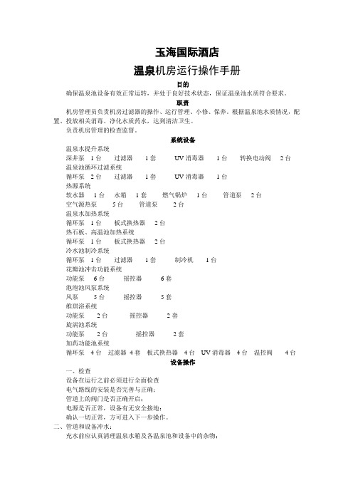
玉海国际酒店温泉机房运行操作手册目的确保温泉池设备有效正常运转,并处于良好技术状态,保证温泉池水质符合要求。
职责机房管理员负责机房过滤器的操作、运行管理、小修、保养。
根据温泉池水质情况,配置、投放相关消毒、净化水质药水,达到清洁卫生。
负责机房管理的检查监督。
系统设备温泉水提升系统深井泵1台过滤器1套UV消毒器1台转换电动阀2台温泉池循环过滤系统循环泵2台过滤器1套UV消毒器1台热源系统软水器1台水箱1套燃气锅炉1台管道泵2台空气源热泵5台管道泵2台温泉水加热系统循环泵1台板式换热器2台热石板、高温池加热系统循环泵1台板式换热器2台冷水池制冷系统循环泵1台过滤器1套制冷机1台花瓣池冲击功能系统功能泵6台摇控器6套泡泡池风泵系统风泵5台摇控器5套维琪浴系统功能泵2台摇控器2套旋涡池系统功能泵2台摇控器2套加药功能池系统循环泵4台过滤器4套板式换热器4台UV消毒器4台温控阀4台设备操作一、检查设备在运行之前必须进行全面检查电气路线的安装是否完善与正确;管道上的阀门是否正确开启;电源是否正常,设备有无安全接地;确认一切正常,方可进入下一步操作。
二、管道和设备冲水:充水前应认真清理温泉水箱及各温泉池和设备中的杂物;1、温泉井提水启动温泉提升泵前,打开泵后闸阀、过滤器六位阀过滤位、温泉水箱前闸阀、游泳池供水闸阀,确认2个转换电动阀为一开一闭,游泳池供水管为常开状态。
(温泉水箱水满后转换电动阀自动转换为温泉供水电动阀关闭,游泳池供水阀开启)2、温泉水加温燃气锅炉加热高温水箱经板式换热器分为温泉水箱加热、热石板、高温池、4个功能池加热。
空气源热泵经循环加热泵直接加热温泉水箱内温泉水。
3、温泉池充水温泉水经循环过滤泵经砂缸、UV消毒器加入温泉原汤池、情侣池、池中池、功能池,原汤池、情侣池、池中池将池水放至溢流口循环回温泉水箱,往复循环,加药功能池将池水放至溢流口下5cm处关闭加水阀,加药后各池单独循环过滤、消毒、加热。
GS+操作指南(睿驰原创)_bd

北京环中睿驰科技有限公司GS+软件操作指南安装、激活、使用方法版权所有,转载注明,谢谢!作者:沈帅qq:971307775 Email:ss@4/2/2012主要介绍GS+软件的安装方法、激活方法、用途特点介绍以及一个完整的建模实例。
1GS+软件操作指南1.1概述GS+软件操作指南主要介绍了GS+的基本操作方法,包括安装、注册、软件命令简介、菜单项介绍,最后包括实际的操作方法。
1.2安装步骤1.2.1步骤一安装软件●GS+ 10 Windows版本安装软件包名称为SetupGSWin9.exe(根据购买版本不同,安装程序名称不同,目前最新版本为GS+ 10),包括有官方提供的因特网直接下载连接,以及光盘版本CD安装包,点击该软件安装包,然后弹出下边界面之后点击允许运行:图一●然后弹出如下界面:图二●点击Next,然后选择安装目录,默认为系统C盘:图三●点击Next,出现如下界面,点击install开始安装:图四安装过程中360或其他杀毒软件会提示报错,点击同意修改,然后完成安装图五图六1.2.2软件激活方法介绍软件安装成功之后,找到GS安装目录,然后会提示进行软件激活操作,如下所示:图七省略1.3软件介绍1.3.1用途GS+在1988年成为第一个在PC机运行的地质统计学软件,是一款先进的地质统计分析软件。
之后快速被全世界用户广泛使用。
GS+是第一个将所有组件集成到一起来完成统计任务,包括有半方差分析,克里金方法以及软件绘制图形。
GS+操作简单,对于专业的地质学家跟初学者都很容易上手。
GS+主要用来将不完整的数据来完成精确、严格的统计地图,这就意味着客户只需要使用较简单的样例数据,通过GS+的统计计算,就可以完成详尽的地质统计结果。
这样在绘制石油分布图或者浮游生物分布图时,GS+就可以自动补充地质的非实测数据。
1.3.2特点1.3.2.1GS+提供空间的自相关分析:GS+提供半方差分析功能,其中包括各项同向跟各向异性方差图模型分析。
GS Yuasa Energy Solutions, Inc. SWU系列产品操作人员通用指南说明书

SWU – General Instructions for Operations PersonnelGS Yuasa Energy Solutions, Inc.CONTENTSSection Page1. PURPOSE (3)2. SWU SERIES (3)3. COMPANY INFORMATION (4)4. CERTIFICATIONS (4)5. SAFETY AND HANDLING (5)6. EQUIPMENT FOR INSTALLATION AND REMOVAL (6)7. TRANSPORTATION (6)8. DELIVERY INSPECTION (6)9. STORAGE (6)Table 9.0-A. Storage Period Based on Temperature (7)10. CHARGING (7)Table 10.0-A. Maximum Recharge Current & Nominal Ah Capacity* (8)11. INSTALLATION CONSIDERATIONS (8)Table 11.0-A. Float and Temperature Compensation (9)12. MAINTENANCE AND REPLACEMENT (10)12.1 ROUTINE MAINTENANCE (10)12.2 END OF LIFE (10)13. DISPOSAL (10)1. PURPOSEThis document is issued to provide general information relating to this specific product line for installation and maintenance personnel. Detailed installation procedures for specific applications are shipped with the installation kit and are also available from your customer service representative. For the purposes of this document a 12V bloc or battery will be referred to as a module.2. SWU SERIESThe SWU series is specially designed for UPS applications. The SWU series is part of an extensive line of maintenance free, gas recombinant VRLA batteries offered by GS Yuasa Energy Solutions, Inc. The 10-year design life SWU is the most cost-effective battery solution over the total life cycle for installation in your network.3. COMPANY INFORMATIONGS Yuasa Energy Solutions, Inc. is a U.S. subsidiary of GS Yuasa Corporation of Japan. The parent company, GS Yuasa Corporation is a global supplier of high quality, long life Valve Regulated Lead Acid batteries (VRLA) batteries as well as many other types of lead acid batteries and other battery chemistries. GS Yuasa is the world leader in motorcycle and standby storage batteries providing solutions for powersports, telecommunications, UPS, renewable energy, and emergency lighting. Offices are in Roswell, Georgia, located 25 miles North of Atlanta, Georgia.Office hours are 8:00AM ET – 5:00PM Eastern Time Monday through Friday. The mailing address and contact infor-mation are below. For technical support, customer service or assistance with this or any other GYES product: Call: 866-472-2879Email: ******************************GS Yuasa Energy Solutions, Inc.1150 Northmeadow ParkwaySuite 110Roswell, GA 30076Phone: 678-762-4818Fax: 678-739-21334. CERTIFICATIONSSpecific technical questions regarding certifications may be referred to our Engineering Department.*****************************************************• ISO 9001:2000 factory manufactured• UL 1989 Listed• UL 94 V-0 Case5. SAFETY AND HANDLINGThe following precautions should be observed when handling and working with batteries. It is recommended you follow your Company’s Safety Procedures and Practices.1. Protect terminals from shorting during transportation.2. Never charge a visibly damaged module (individual 12V battery or bloc).3. Never charge a frozen module.4. Keep sparks or other sources of ignition away from module.5. Use insulated tools to reduce the risk of shorting while installing or removing module.6. Do not lay tools or metals objects on the top of module.7. Remove watches, rings and other jewelry when working around modules.8. Eye protection and protective footwear are recommended and may be required by your employer.9. Verify circuit polarity and string connections before connecting to the power system.10. Use proper lifting technique, mechanical lifting equipment or assistance as required when removing or installingmodules.11. Disconnect the module or string of modules from the DC power system or common DC bus prior to removal.12. The operating area should be ventilated.13. Modules contain diluted sulfuric acid.CAUTION:While the module case is in tact, it is unlikely the user will come in contact with the acid contained inside. Should acid come in contact with eyes, flush the eye with water or eye wash solution and seek medical attention. Should acid come in contact with skin, wash with affected area with water and neutralize immediately to avoid chemical burns.6. EQUIPMENT FOR INSTALLATION AND REMOVALThe following are recommended for personal protection and safe installation or removal of modules.1. Insulated hand tools.2. Fire extinguisher.3. Acid spill kit.4. Eye protection.5. Eye wash.6. Mechanical lifting equipment may be required in certain applications such as controlledenvironmental vaults.7. TRANSPORTATIONModule terminals should be protected from shorting during transportation. New modules should remain in the original packaging material to protect the case and terminals until they are to be installed. Shock or ‘bruising’ caused by dropping or rough handling of a module can cause internal damage to plates, inter-cell straps, or compromise the integrity of the case. Modules being removed from service should likewise be protected when being transported from the job site or to the recycler. The SWU series is rated ‘NON-SPILLABLE’ and should be so labeled during shipping. The Safety Data Sheet (SDS) is available for download at the following link: 8. DELIVERY INSPECTIONUpon receipt inspect the pallet and packaging for visible damage. Inspect the module terminals and terminal hardware for damage or missing parts. Many shipments include installation kits; application specific installation manual, terminal bolt kits, cable assemblies, lugs, module trays or module stands. The entire shipment should be verified to ensure all components associated with the shipment are present. If missing components or damage is discovered, contact your freight carrier or GYES for instructions.9. STORAGEModules should be stored in a cool, clean and dry place not to exceed the range from -20° to 40°C (-4° to 104°F). Modules shipped directly to the customer do not require refresh charging upon receipt. Modules stored for extended periods may require a refresh charge prior to installation or further storage (Table 9.0-A). The Open Circuit Voltage (OCV) should be measured before installation and periodically during storage. Modules with an OCV of 12.5V or above at 25°C (77°F) do not require refresh charging.Should the OCV be less than 12.5V, apply a refresh charge by charging the battery for 48 hours at 13.6V at a current not to exceed 25% of rated capacity.Table 9.0-A. Storage Period Based on Temperature10. CHARGINGPerformance and life are in part influenced by the power system and the operating temperature. This is especially true for batteries used in standby float applications. The operating temperature range for the SWU series is -40°C to +65°C (-40°F to 149°F). However, short term excursions to 65°C (149°F) are permissible.Float voltage and properly functioning temperature compensation are keys to long battery life. The recommended float voltage range at 25°C is 2.25-2.3VpC and may be found on the product label. High temperature compensation begins at 26°C and low temperature compensation begins at 24°C. The exact points at which temperature compensation begin can be varied slightly as long as the battery is kept within the recommended float range adjusted for temperature. The rate of increase for low temperature compensation is +0.003V per degree centigrade per cell (+3mV/°C/cell) and the rate of decrease for high temperature compensation is -3mV/°C/cell.NOTE: Charging should be conducted in a cool, dry and well ventilated location. The batteries should not be exposed to direct sunlight during charging or storage. Temperatures should optimally be in the range of 21°-25°F (70°-77°F). The charging current should be regulated to 25% of the rated capacity of the battery. For example, a 100Ah battery rated at the 8 hour rate should not be charged at a current above 25A.Batteries should not be allowed to fall below 12.5V during storage. Batteries between 12.1V and 12.4V may be recovered and further stored by applying a refresh or boost charge. In the unlikely event batteries are stored beyond the point where the OCV falls below 12.1V, contact GYES Customer Service.11. INSTALLATION CONSIDERATIONSIn this section are general considerations for battery installation.1. Review your Company’s Safety Practices and Section 5 “SAFETY AND HANDLING”.2. Acceptance prior to installation should include a visual inspection for damage or abnormalities in additionto verifying the OCV is 12.5V or above (Section 9 “STORAGE”).3. Do not install modules in an airtight enclosure.4. Modules may be installed in an electronics equipment cabinet where required.5. Lift and move modules carefully to avoid personal injury or damage to the module.NOTE: In some cases, this may require two technicians or mechanical lifting equipment. Never lift amodule by the terminal or an attached battery cable or battery supply harness.6. Do not install modules that have been dropped, damaged or show any indication of leakage or corrosion atthe terminals.NOTE: Damage to the case or terminals may result in premature failure or shorten the life of the module.Table 10.0-A. Maximum Recommended RechargeCurrent & Nominal Ah Capacity *NOTE: Your Company may have specific guidelines for float voltage and temperature compensation calculated to keep the module or string within the recommended range adjusted for temperature.Excessive current while recharging the module or string after a discharge event may cause internal heating. The maximum recommended recharge current for the SWU series is found in Table 10.0-A.7. Do not install modules near sources of ignition.NOTE: Under abnormal operating conditions, VRLA modules may generate flammable hydrogen gas.Gassing due to overcharging may occur due to a power system malfunction, improperly adjustedfloat voltage or temperature compensation or a shorted cell.8. Verify the polarity is correct before connecting the load or power system to a module or string of modules.9. Do not mix new and old modules together in the same series string.NOTE: GYES recommends modules greater than 1.5 years in service not be mixed in the same series string due the risk of string imbalance. As modules age, charge acceptance will also change.10. Modules being connected in series to form a string should be at or near the same state of charge.11. Modules installed as a string should be numbered starting with module #1 at the main positive thensequentially number each module to the last module at the main negative terminal of the string.12. Allow at minimum 2mm spacing between modules where the additional space is available on the moduletray or inside the module compartment. Additional separation is desirable when available.13. Clean terminals and cable connections with a brass wire brush before assembly.NOTE: The application of electrical grade grease such as Sanchem No-Ox-ID A-Special is permitted.14. Damaged or corroded lugs or cabling should be repaired or replaced before installing a new module orstring of modules.15. Connections to module terminals should be made using the recommended torque specified on the productlabel.CAUTION: Excessive torque may lead to post seal failure.NOTE: All M6 top terminal bolts should be tightened to 43.5in-lbs. Re-torque is not required for anyGYES terminal hardware. However, if required by your Company, re-torque to 43.5in-lbs.16. Verify the power system float voltage and temperature compensation are set correctly (See Table 11.0-Abelow and Section 10 “CHARGING”).NOTE: Your Company may have specific guidelines for float voltage and temperature compensationcalculated to keep the module or string within the recommended range adjusted for temperature.Table 11.0-A. Float and Temperature CompensationGS Yuasa Energy Solutions, Inc.1150 Northmeadow Pkwy. Suite 110Roswell, GA 30076 (800) 472-2879ABOUT GS YUASA ENERGY SOLUTIONS, INC.GS Yuasa Energy Solutions, Inc. is an American subsidiary of GS Yuasa Corporation, the world’s second largest battery company and a 100+ year old Japanese corporation. GS Yuasa Energy Solutions (GYES) was formed in 2019 to address the growing energy storage and reserve power markets. GYES brings together and leverages GS Yuasa Group’s advanced technologies with proven American market successes in lithium, telecom, UPS, alarm & security, and energy storage into a single business unit.500-100-093 R e v .3.0 09-202012. MAINTENANCE AND REPLACEMENT12.1 Routine MaintenanceRoutine maintenance is not required by GYES. Visual inspection of the module casing and terminals may be included as part of your Company’s site or power system routine practices. This visual inspection should be used to identify physical abnormalities such as corrosion, swelling, cracking, or leaking which indicate a need for further testing or evaluation of the modules and power system. Re-tightening module terminal hardware is not required. However, if your Company requires re-torque as part of a routine maintenance, the terminals should be carefully tightened with a torque wrench to the specification found on the product label.The life of the module is greatly influenced by the power system. In all cases float voltage should be set and adjusted for temperature (See Section 12 “CHARGING”). In non-environmentally controlled applications, temperature compensation is required. It is imperative the power system be adjusted correctly for float and temperature compensation and a thermal or temperature probe installed on the string.The ability of the power system to correctly adjust the float for temperature is dependent on the power system’s temperature or thermal probe. Module temperature is best read by a thermal probe placed on the side of the battery for ‘paddle type’ probes or on the negative terminal for ‘ring-type’ probes. Periodic or routine maintenance of the power system is essential to maximizing life.Battery recharge current limit should be adjusted where required to limit the current during a recharge event. See Section 12 “CHARGING” for maximum recharge current recommendation.12.2 End of LifeModules or a module string should be replaced when they have reached End of Life. The EOL is defined as 80% of rated capacity as determined by a constant current discharge test.13.DISPOSALLead acid battery recycling is an environmental success story. More than 95% of all battery lead is recycled. Cooperation between suppliers and customers make this closed loop life cycle possible. Batteries should be recycled in accordance with applicable government regulations. For more information about recycling, contact GYES or see or .。
gs热熔机使用操作流程

gs热熔机使用操作流程English Answer:GS Hot Melt Machine Operating Procedures.Before operating the GS hot melt machine, it is important to familiarize yourself with the safety precautions and proper operating procedures.Safety Precautions.Always wear appropriate personal protective equipment (PPE), including gloves, safety glasses, and a mask.Keep the work area clean and free of debris.Do not operate the machine if it is damaged or malfunctioning.Allow the machine to cool down completely beforeperforming any maintenance or repairs.Operating Procedures.1. Preparation.Ensure that the machine is plugged into a grounded electrical outlet.Fill the glue tank with hot melt adhesive.Set the temperature of the glue to the recommended setting for the type of adhesive being used.2. Operation.Turn on the machine and allow it to reach the desired temperature.Place the material to be bonded on the work surface.Apply a bead of hot melt adhesive to the materialusing the glue gun.Hold the material in place until the adhesive has set.3. Shutdown.Turn off the machine and allow it to cool down completely.Empty the glue tank and clean the machine with a suitable solvent.Store the machine in a cool, dry place.Maintenance.Regularly inspect the machine for any signs of damage or wear.Clean the glue tank and nozzle as needed.Lubricate the moving parts of the machine according tothe manufacturer's instructions.Troubleshooting.If the adhesive is not flowing properly, check the temperature setting and the glue tank level.If the adhesive is burning, the temperature may be too high.If the material is not bonding properly, the adhesive may not be the correct type or the bonding time may be too short.中文回答:GS热熔机使用操作流程。
- 1、下载文档前请自行甄别文档内容的完整性,平台不提供额外的编辑、内容补充、找答案等附加服务。
- 2、"仅部分预览"的文档,不可在线预览部分如存在完整性等问题,可反馈申请退款(可完整预览的文档不适用该条件!)。
- 3、如文档侵犯您的权益,请联系客服反馈,我们会尽快为您处理(人工客服工作时间:9:00-18:30)。
前言GS 温泉管理系统是深圳市捷信达电子有限公司凭借十数年的酒店管理软件行业的专业专注和经验累积,结合业界人士的专业知识开发的一套用于温泉娱乐中心管理的系统。
GS 温泉管理系统在模块构造上做到了灵活多用、功能齐全。
既适用于大型娱乐休闲中心又适宜中小型规模的温泉场所。
GS 温泉管理系统各模块之间功能划分严密,在保持紧密联系的同时也能独立运行,以便不同职位操作员进入相应模块就可执行职责范围内的所有操作。
每个操作员(如钟房操作员、收银操作员、技师操作员、接待操作员)进入对应的模块(预订、接待、钟房、技师、消费、楼面、收银、维护)操作前都需要验证身份。
避免了操作员在系统中越权越级操作,保证了操作人员的工作效率,杜绝出现管理上的漏洞。
并且,系统大部分操作都有引导提示和错误提示,减少操作员差错的机率。
GS 温泉管理系统的另一个特点是报表丰富,分类齐全,相关的营业数据及服务数据在报表中均有体现。
管理者能实时方便地查看不同阶段的营业状况及服务员的工作状况,为经营决策提供重要依据。
另外,GS 温泉管理系统自身预置了大量的基础数据,涵盖了温泉中心大部分业务内容。
并备有大量的基础数据和参数供用户设置。
其中的一部分在系统投入使用前预先设置(如服务项目的设置、服务收费标准、相关操作员权限、划分分厅设置、报表查看权限划分、优惠折扣率、及其它特色消费等内容)。
另一部分则可根据本中心营销政策和经营内容进行设置,并可在系统运行过程中。
继续维护和更新,这种灵活的区分设置便于用户更好地用到GS 温泉管理系统的全部功能。
每个优秀的管理系统的成长都离不开用户的支持,我们希望每一个使用GS 温泉管理系统的用户都能将自己在使用过程中的建议和意见反馈给我们,以使GS 温泉管理系统更趋完善GS 温泉管理系统说明书一、 温泉一般流程如下图宾客入前厅(进场) 前厅相关人员电脑登记发放匙牌带宾客进更衣室宾客离场 其它消费区消费录入电脑(如餐饮、商场)钟房安排好技师,做好记钟,下钟工作宾客买单(凭匙牌买单日,回收匙牌) 收银(单据查单)打印帐单二次更衣消费录入电脑楼面大厅消费录入电脑(大堂项目)温泉管理系统分八大模块:预订\接待\消费\钟房\技师\楼面\收银\维护。
温泉主界面温泉各模块登陆界面:二、熟悉大概的工作和流程,下面就让你了解系统的运作和功能。
预订一、预订管理模块为两个块:客户管理档案和预订管理系统。
1、客户管理档案:主要是把一些与公司有合同的客户进行统计,方便管理,此功能有权限控制,分地区、销售员及客户类型(企事业\旅行社)统计。
每次预订时也可通过预订管理系统直接调用客户档案的客户,方便、快捷。
且有了客户管理档案就可统计各地区及销售员的业绩报表(每日实到表、每日未到表、各地区销售报表、销售员业绩报表、各单位消费明细报表等)(图1)(图2)2、预订管理系统:预订管理是由预订部进行操作控制,把每次的订单收聚后录入,只要在预订管理系统下订单后,各部门通过电脑都可查询,也有报表反映,同时前厅接待的如是预订客户也直接调入进行操作,使此预订由等待变为已到,方便预订部进行客户跟踪。
3、预订界面如下:(图3)(图4)接待1、接待是温泉核心之一。
温泉由于接待流量在,所以要达到能够快速登记,让客人进场。
2、如有预订客人也可先把匙牌先预订好,客人到场后直接一键启用便可,接待流程方便快捷。
接待主界面如下,清楚明了,可看到每批客人的相关信息!(图5汇总显示)(图6明细显示)3、接待登记界面功能强大,可按门票分类登记,如散客、多种团队等,可直接登记调预订信息。
也可对预订客人先做匙牌预留,预订客到达后直接调预留匙牌快速登记。
界面信息明了,方便操作,接待登记界面支持手工录入和电子打卡,每日有客类统计报表。
登记界面如下(图7)4、温泉为了能快速为客人买帐离场(如团队的司培把人数确定后就要先把门票先买帐,因可能有事情要先离开,这种情况在系统可用手工登记功能,接待先登记人数不用针对匙牌,再由收银针对本批客人打单,买单。
手工登记界面如下(图8)5、预订:接待在登记时有预订客人直接调预订,选择对应的预订便可。
(图9)6、调单:可通过调单去查询客人,可查询匙牌、批号、客人姓名。
(图10)7、类型:可查询客人各类型消费情况,可多选。
(图11)8、折扣:折扣界面功能强大,可对单个匙牌打扣,可对同批客人打折,也可对各消费类型进行打折。
(图12)5、读房卡:针对酒店客人,酒店客人来泡温泉接待可通过读取房卡及可对客人进行不同折扣的打折。
(图13)6、修改信息:此功能强大,可修改备注、匙牌、门票价(可批量)、改预订等。
(图14)7、组合:对不同批的客人进行组合,也可能不同批又不同门票的客人进行组合后,可取任何一种客类(也就是门票)。
(图15)8、部分转帐:此功能是满足一批客人如门票(可按类别)由其中一位客人买单,其它消费自付的情况,方便收银买单。
(图16)9、匙牌查询:功能可看到匙牌是否在场,也可实时看到各情况的匙牌及人数(总人数、批号、在场人数、离场人数、男宾、女宾等)。
(图17)总结:以上功能都是接待在日常操作中所涉及的,系统针对温泉快进快出的运作模式进行专业设计。
其中登记界面是最为主要的,为方便操作员的使用,此功能目前也是最为简单又快速的。
消费1、消费:消费是对客人在温泉中心接受的每笔服务收费项目的记录。
当客人需要消费时,服务人员先为客人下手工单,之后到相对应的电脑下单(对应匙牌、消费项目、位置号),各出品点自动出品。
消费界面如下:(图18)2、直接点击或通过编号查询匙牌都可以为匙牌录入消费项目录入匙牌:(图19)3、进入消费项目消费(图20)4、在消费项目界面也可看到此匙牌的相关信息:匙牌、客类、客人、批号、备注等。
5、数量:针对消费项目数量。
(图21)6、单价:针对一些时价的项目,如赔偿费等。
(图22)7、技师:针对一些大堂消费项目或小费(图23)8、单号:服务员为客人下手工单的单号,方便收银和财务查帐。
(图24)9、编号:点商品的一种方式,直接录入项目的编号即可。
(图25)10、小费录入:各消费点的小费录入。
(有小费报表,方便财务为技师发小费)(图26)11、高级:一些附助功能。
(图27)12、部分转帐:把一个匙牌的一项或多项消费转到另一个匙牌。
(图28)(图29)13、取消/赠送界面:如需为某个匙牌取消或赠送项目必须录入原因,要不不能保存,也有相对应的取消和赠送报表进行统计。
(图30)14、如有赔偿费也可把相对应的说明在备注写上。
方便收银知道为什么要收赔偿费。
消费项目操作简单、方便,数据实时反映到各消费点。
钟房钟房是温泉中心的主要服务中心,温泉中心的大部分服务项目均在此展开,客人的消费基本上都发生在钟房.因此,钟房操作员的工作在GS温泉管理系统里是至关重要的。
它涉及的每步操作都将牵涉到相关模块的相关变动。
如在收银模块,客帐单将体现客人在钟房的各种消费项目和金额,为了便于温泉中心的管理,对钟房的工作职责进行严密区分。
需对钟房操作员的操作权限进行划分。
在维护模块可以预先设置钟房操作员的操作权限。
需要注意:的是不是所有的钟房操作员都能执行钟房模块的全部操作功能,只有具备了相关操作权限的操作员才能执行相关的操作功能。
钟房操作流程:客人从消费区到保键区后,保键区相关人员为客人安排好房间后通知技师房安排技师。
技师房接到信息后,在电脑这此房间安排技师后,技师凭电脑出工单直接进房为服务按摩,技师到房间按摩前需电话通知钟房相关人员起钟。
如客人需要加钟或要落钟,技师都要通知钟房对电脑进行操作。
钟房主界面分为三个区域:左边区域为所有匙牌的状态,中间区域为起钟或即起的状态。
右边区域为当班空闲技师的轮牌情况。
下面为钟房操作的一些功能键。
(图33)1、功能(图34)2、开房界面:在保键都会有这类房间,称为贵宾房。
它可直接对外,不用通用匙牌,按时收房费,以虚拟匙牌控制。
(图35)3、起钟:客人开始做钟称为起钟,由系统计时。
(图36)4、加钟:客人做完若干个钟之后还继续做钟称为加钟。
(图37)5、落钟:客人做完钟(到时)后钟房所做的操作,起确定钟数的作用。
(图38)7、查找客人:(F2)键入客人钥匙号回车所,系统定位到该项钥匙所在行的位置,方便查看人当前状态。
(图39)8、查找房间:(F3)键入房间号回车后,系统定位到该房间正在上上钟的所有客人的位置。
(图40)9、查找技师:(F4)键入技师回车后,系统定位到该技师所在位置,包括正在上钟或空闲的技师。
(图41)10、预约:客人提前对熟的技师进行预约。
(图42)11、技师预约编辑界面:(图43)12、换房:(C)客人由一个房间换到另一个房间时,钟房需要在电脑上所做的操作。
(图44)13、退房:客人由于某种原因离开而取消开房登记称为退房,不计消费。
(图45)14、修改起钟时间:对原来起钟的时间进行修改。
(图46)15、技师换出:(E)起钟之后客人对当前技师不满意或其它原因而要求更换技师称为技师换出,可以同时换入另一技师,如暂不换入另一技师,可稍后再执行“技师换入”。
(图47)16、换做钟类型:(H)由原来的做钟类型更换为另一各做钟类型,如由中式改为泰式。
(图48)17、修改钟数:(D)对正在做钟的客人做钟钟数进行修改。
(图49)18、退钟:(L)客人在起钟后由于某种原因而要求终止做钟,不计消费。
(需要授权)(图50)19、反落钟:(M)执行过“落钟”操作后,由于某种原因需要将落钟状态恢复为起钟状态。
(图51)20、技师对调:(P)将两位客人的技师对调,但客人的做钟类型不能对调,所以在这操作之前应考虑到两位技师是否都能根据客人需要理换做钟类型。
(图52)21、加时:经管理人员同意后,给客人延长做钟时间,延长时间不计入消费的称为加时。
(图53)22、技师起落钟记录查询:根据钥匙号、房间号、技师号中的任意一个条件可查询一个或多个营业日某技师的上钟记录。
(图53)23、技师起落钟查询:(图53)24、技师信息:(F7)查询某技师基本资料及当前状态,包括姓名、性别、籍贯、年龄、组别、工种、联系电话、是否有预约,如果该项技师在上钟,即可查看所在房间号及客人钥匙、做钟类型、起钟时间等等。
(图54)25、综合房态:(F11)此界面显示所有房间当前的使用状态及技师轮牌表、上钟状况等,同时还具有钟房主界面的所有功能。
(图55)26、客账查询:(F8)对账单进行明细查询,包括已经买单的账单。
(图56)(图57)技师GS 温泉管理系统技师模块主要为温泉中心提供对技师的管理。
包括技师资料管理、技师工作状况管理、技师考勤管理。
同时,对技师进行优劣评级,并按温泉中心相关政策对技师进行奖惩。
其中技师资料管理又包括增加修改删除技师资料,技师工作状况管理包括当前是否做钟做钟时长等内容。