STV3中文说明书V3.03
ST-G3 车载数据分析仪用户手册说明书
法律声明版权所有深圳市易检车服科技有限公司。
保留一切权利。
非经本公司书面许可,任何单位和个人不得擅自抄袭、复制本文档内容的部分或全部,并不得以任何形式传播。
注意本文档中描述的全部或部分产品、服务或特性可能不在您的购买或使用范围之内。
除非合同另有约定,易检车服公司对本文档内容不做任何明示或默认的声明或保证。
手册升级,恕不另行通知,若需最新手册,请通过以下方式获取:与您的产品销售商联系;登陆易检车服官方网站下载。
重要提示本手册介绍了如何正确使用本产品。
操作手册所述流程前,请务必认真阅读安全注意事项后再使用该产品。
安全信息文中使用的指示图标说明如下:说明说明突出重要信息和使用窍门,对您的操作进行必要的提示、补充和说明。
注意提醒您在操作中必须注意和遵循某些事项。
如未按照要求操作,可能会出现设备损坏、数据丢失等不可预知的结果。
警告警告您可能会存在潜在的危险,若无法避免,可能会造成较为严重的人身伤害。
更多服务服务热线:400-930-1883注意事项• 请勿在多灰、潮湿、肮脏或靠近磁场的地方使用设备,以免引起设备内部电路故障。
• 请勿在雷雨天气使用本设备。
雷雨天气可能导致设备故障或电击危险。
• 请在温度0℃到50℃范围内存放设备及其配件。
当环境温度过高或过低时,可能会引起设备故障。
• 请勿将设备放置在阳光直射的地方,如汽车仪表盘或窗台处。
• 请避免设备及其配件雨淋或受潮,否则可能导致火灾或触电危险。
• 请勿将设备靠近热源或裸露的火源,如电暖器、微波炉、烤箱、热水器、炉火、蜡烛或其他可能产生高温的地方。
包装清单以下附件仅供参考,详细包装清单,请参考随机附带的装箱清单或咨询当地经销商。
• 主机• 开关电源• 测试主线•••••• XTA001芯片转接座• 奔驰红外模拟采集钥匙•• 产品手册MCU转接板V1MCU转接板V2四代仪表免拆EEPROM全丢线BENCH模式线MCU飞线EEPROM转接板目录1 关于本手册 (1)1.1 目标读者 (1)1.2 约定 (1)1.3 图标定义 (1)2 关于ST G3 (2)2.1 产品介绍 (2)2.2 技术参数 (3)2.3 电源 (4)2.4 配件列表 (4)3 诊断 (6)3.1 常用操作 (6)3.1.1 建立硬件连接 (6)3.1.2 建立无线连接 (7)3.1.3 执行常规操作 (7)3.2 诊断操作 (8)3.2.1 钥匙编程 (8)3.2.2 变速箱编程 (13)3.2.3 发动机编程 (16)4 软件升级 (24)保修信息 (25)服务信息 (25)1 关于本手册本手册包含了产品操作使用说明。
达南锁通用模块V3用户指南说明书

Universal Module V3 User guideContentsProduct information page 3 T echnical specifications page 4 Wiring diagram page 5 Wiring diagramDoor strike / Magnetic door lock page 6 Installation page 7 Setup page 8-9 Remote access/Integration page 10 Support page 11Product information 3/12 The Danalock Universal module is a device for controlling all 12-24V powered commercially available locking mechanisms; door strikes, electromechanical or magnetic locks, gates etc.The module works in parallel with what is already installed or in any new installation.The module has two relay outputs and one power output. The relays or the power-output can be controlled remotely with the Danalock app via Android (from version 4.4.4) and iOS (from iOS 9.0 and iPhone 4S) smartphones. The relay is both Bluetooth Low Energy 4.0 and/or Z-Wave driven.Relay modeThe two relays can be operated either parallel or separately. The relays are working for a desired time (1-180 sec.) or permanent when activated. The activation for the relays can be delayed for relay 2 after activating relay 1. The two relays can be setup individually for permanent activation or for a desired time.T echnical specifications 4/12 Operating voltage range 12-24V DC, 12-24V ACMax input (at 24V) 100mA Number of relays 2 Type of relays Potential-freecontacts (NO/NC) Max AC power 1A at 12V Max AC current 1A at 12V Max relay voltage 48 VWireless communication Bluetooth 4.0LE/Z-Wave Plus (optional) Bluetooth range 5-10 metersWiring diagram 5/12ellowWiring diagram - Magnetic door lock 6/12BlackGrey Power input 12-24V AC/DC 1 ampGrey 12/24 in White 12/24 inBrown GroundWhite Ground input 12-24V AC/DC 1 amp Red Yellow Green Relay 2: Normally openViolet Relay 2: Normally closedBlue Relay 2: CommenWiring diagram - Door strike7/12Grey 12/24 in White 12/24 inInstallation 8/12 1. Mounting instructionConnect the Universal Module to the relevant motor drive while considering the wiring diagram.Note!Please make sure to connect the Universal Module to a smartphone during installation. As soon as you are registered as owner, no one else is able to control the door/gate, and it is only you who can grant other users access.2. Connect to the smartphoneT o connect the Module to a smartphone, please follow the Danalock App User Guide on:https:///?page_id=2894When installing the Module you will be asked to set the Relay time. In the User guide for the motorized door lock you will find the recommended time (pulse = 1sec). Per default, the Universal Module will switch off after 1 sec.Note!The Relay time can be changed under settings at any time.User Guide 9/12Y ou find the updated version of the Danalock App User Guide under:https:///?page_id=2894Among other things, the guide will show you how to share access. If you like to change owner/administrator of the Module, you have to delete the Module from the app before connecting it to a new owner.Note!Please only delete the Module from the keychain when in Bluetooth range of the Module. If you are not in Bluetooth range, you will have to reset (see “T ouch button commands) it by pressing the button on the Module. If the Module is a built-in solution, a reset can cause additional charges from eg. a locksmith.T ouch button commands 10/12 Y ou find the gold-colored touch button in one corner of the circuit board. One short press switches the Relay off. Holding down/pressing the touch button will trigger the following commands:1 flash switches the relays off.2 flashes puts the Module inZ-Wave inclusion mode.5 flashes resets the key.10 flashes means a factory resetof all key and relay settings.Remote access/Integration 11/12DanabridgeThe Universal Module is only accessible when the user is in Bluetooth range. T o gain remote access, you can use a spare smartphone or tablet: https:///?page_id=2981Z-WaveThe Danalock Universal Module with Z-Wave is compatible with a long list of gateways.Read more about it here:https:///?page_id=2597Support 12/12You will find a list with frequently asked questions here: https:///?page_id=3417Please write or call us in case of any questions:+0045 42428122Poly-control ApSGammel Stillingvej 427 C, 8462 Harlev - DK*************************************+45 4242 8122。
科赛ST3000上位机中文说明书ST3K

:波形放大显示。版辊周长比较大时,信号相对较小,此时放大信号有利于观察。可选择比例在1倍、2倍、4倍。注意:此处的放大仅为横向放大,信号幅度无任何变化。
:单通道智能开关。按下按钮,电脑自动将本组所需信号移动到波门内,同时本组进入自动工作方式,电脑自动跟踪。“ ”表示本组智能关;“ ”表示本组智能开。
系统采用集散式控制结构,实现了现场对版误差的识别、修正和确认,减少了废品率;
下位机采用彩色液晶屏,简单、直观、方便,可随时调整参数,调节光电眼更直接、更快捷,提高了产品的合格率。
既可在上位机控制下工作,也可脱机(无上位机)工作。
成熟的色标检测技术,符合国际印刷色标排列惯例(纵排或横排)和色标形状(长方形、梯形等);
预套准功能;
完成色标排列、色标形式、版周长、色组设置等功能;
完成波形显示和寻址功能。
3、印刷参数调整。
主要完成A/B系的选择、色组设置、色标排列、色标形式等参数设置。
4、参数输入键盘。
用于对设置项目中数值的输入。
5、菜单显示/隐藏键。
“科赛电脑套色”既作为产品的标志,又可作为工程师菜单(又言:调试菜单)的显示或隐藏,中文和英文操作语言的切换功能。
通道选择:这里的通道指的就是所安装控制单元的机组号。3U表示第三机组。
:工作系属选择,即A/B系选择。一般我们选择A。
:整机自动/手动转换。“ ”表示整机手动;“ ”表示整机自动。
:报警喇叭开关。“ ”表示报警喇叭关;“ ”表示报警喇叭开。
:整机智能模式。“ ”表示整机智能关;“ ”表示整机智能开。
为适应当前印刷机的发展,ST3000型自动套色控制系统可在10米/分到1000米/分的印刷速度内正常工作。
PowerBox Sensor V3 用户手册说明书
SEnsorV3Sehr geehrter Kunde,wir freuen uns, dass Sie sich für die PowerBox Sensor V3 aus unserem Sortiment entschieden haben. Wir wünschen Ihnen mit der PowerBox Sensor V3 viel Freude und Erfolg!PRODUKTBESCHREIBUNGDie PowerBox Sensor V3 ist dritte Generation der weltweit bekannten PowerBox Sensor. Die PowerBox Sensor ist aufgrund ihrer kompakten Bauform und der viel-seitigen Einsatzmöglichkeiten schon seit fast 20 Jahren der Standard in kleinen bis mittelgroßen Modellen.Die Sensor V3 konnte dank dem Einsatz modernster Bauelemente deutlich verklei-nert werden. So wurde die Tiefe von 22 mm auf 11 mm genau halbiert. Trotzdem passt die Sensor V3 exakt in den Ausschnitt seines Vorgängers!Durch den Einsatz eines edlen, gefrästen und eloxierten Aluminiumgehäuses wurde die nutzbare Kühlleistung deutlich erhöht – die PowerBox Sensor V3 kann ca. 35 % mehr Dauerstrom leisten! Die kurzzeitige Belastbarkeit hat sich sogar verdoppelt – über mehrere Sekunden verkraftet die Sensor V3 über 20 A!Die Sensor V3 hat zwei wählbare Ausgangsspannungen – für normale Servos kann auf 6.0 V geregelt werden, für HV Servos stehen geregelte 7,8 V zur Verfü-gung, sofern der Akku eine höhere Eingangsspannung liefert!Als Stromversorgung kann zwischen vier verschiedenen Akkutypen gewählt wer-den: LiPo, LiIon, LiFePo und NiMh. Zur Spannungsanzeige der Akkus kommen ul-trahelle RGB LED´s zum Einsatz die mit verschiedenen Farben den Ladestatus der Akkus signalisieren.Für CORE Kunden gibt es noch ein besonderes Feature oben drauf: beide Akku-spannungen können per Telemetrie direkt auf dem Sender angezeigt werden!FEATURES+ Leistungsstarke Akkuweiche+ Sehr leichte und kompakte Bauform+ Doppelt geregelte Ausgangsspannung+ Redundante Schalter- und Reglerauslegung+ Einstellbare Ausgangsspannung 6,0 V oder 7,8 V+ Spannungsanzeige für jeden Akku separat über RGB LED´s+ Telemetrie-Unterstützung für die CORE+ 4 Akkutypen werden unterstützt: 2s LiPo, 2s LiIon, 2s LiFePo and 5s NiMH+ Reglerüberwachung+ Unterdrückung von Servo-Rückströmen1. AUFBAU UND ANSCHLÜSSE2. EINBAU UND ANSCHLIESSEN DER AKKUSDie PowerBox Sensor V3 wird an einer schwingungsarmen Stelle im Modell ein-gebaut. Reine GfK-Seitenwände eines Motormodells sollten mit einem 3 – 4 mm starken Sperrholzbrett, das von innen eingeklebt wird, gestützt werden, um Vibrati-onen zu minimieren und den Schrauben sicheren Halt zu geben.Stecken Sie zwei Akkus Ihrer Wahl – richtig gepolt – an die Akkueingänge an. Es können je 2x 2s LiPo/LiIon, 2s LiFePo oder 5s NiMH Akkus verwendet werden. Wir empfehlen Ihnen den Einsatz der PowerPak 2.5x2 Pro Akkus, die dank der integ-rierten Ladetechnik besonders sicher und einfach in der Handhabung sind.Akkuanschlüsse RGB LED´s zur Spannungs- und ZustandsanzeigeAusgänge zum EmpfängerHinweis bei selbst konfigurierten Akkupacks: Wird der Akku falsch gepolt an-gesteckt, sind die eingebauten Linear- Regler sofort zerstört!Die Ausgänge der Weiche können je nach Empfängertyp unterschiedlich ange-schlossen werden. Die Ausgänge der Sensor V3 sind einmal 2-adrig und einmal 3-adrig. Bei allen Systemen außer CORE sind die beiden Ausgänge als identisch zu betrachten.Bei Empfängern, die nur einen Akkueingang haben, wird ein Ausgang der Sensor V3 an den Akkueingang des Empfängers angeschlossen, der andere an einen frei-en Servoausgang. Sollte kein Servoausgang mehr frei sein, kann ein V-Kabel an einen Servoausgang angesteckt werden, um die Sensor V3 und das Servo anzu-schließen.Bei CORE Empfängern sollten Sie beachten, dass die 3-adrige Leitung am P²BUS- Eingang des Empfängers angeschlossen werden muss, um die Telemetriedaten der Akkus auf den Sender zu bekommen.Wichtig: Die 2-adrige Leitung wird an einen freien Servoausgang angeschlos-sen – nicht am Fasttrack Ausgang! Die Versorgungsleitung von den P²BUS und Fasttrack Steckern zu den vorne angeschlossenen Servos reicht möglicherwei-se nicht aus, um alle angeschlossenen Servos zu versorgen!3. EIN- UND AUSSCHALTVORGANGDie Sensor V3 hat im Gegensatz zum Vorgängermodell nur noch eine Taste – das vereinfacht den Ein- und Ausschaltvorgang. Wie auch bei anderen PowerBox Gerä-ten mit einer Taste ist der Ein- und Ausschaltvorgang wie folgt:Drücken Sie die Taste ein bis zwei Sekunden, bis die LED´s violett leuchten, lassen Sie die Taste kurz los und bestätigen Sie mit einem zweiten, kurzen Tastendruck den Schaltvorgang.Einmal eingeschaltet kann die Weiche nur wieder mit den Tasten ausgeschaltet werden. Wackelkontakte oder Unterbrechungen während des Betriebes führen nicht zu einem Ausschalten der PowerBox. Der letzte Schaltzustand wird immer abgespeichert.4. EINSTELLEN DER AKKUANZEIGEDamit die LED Akkuanzeige richtig funktioniert, müssen Sie den Akkutyp einstellen. Dazu schalten Sie zuerst die PowerBox ein. Jetzt drücken Sie erneut die Taste und halten diese gedrückt.Nach ca. 5 Sekunden schalten sich die LED´s aus und eine Sequenz mit verschie-denen Farben beginnt. Jede Farbe ist einem Akkutyp zugeordnet. Lassen Sie die Taste los, wenn die Farbe angezeigt wird, die Ihrem Akkutyp entspricht. Der Akku-typ wird damit abgespeichert.0 – 20 %Information zur LED Anzeige: Die Anzeige ist nicht linear zur Akkuspannung. Es wurden verschiedene gängige Akkutypen vermessen, die im Mittel eine Entlade-kurve ergeben. Diese Entladekurve wird verwendet, um eine prozentuale Anzeige zu ermöglichen.Die LED Anzeige hat folgende Bedeutung für den Akkuinhalt:5. EINSTELLEN DER AUSGANGSSPANNUNGDie PowerBox Sensor V3 kann auf zwei verschiedene Ausgangsspannungen ein-gestellt werden. Zum einen auf 6,0 V für reguläre Servos und zum anderen auf 7,8 V für HV Servos. Achten Sie bei dieser Einstellung darauf, dass alle angeschlossenen Komponenten hochvolt-tauglich sind.Der Vorteil daran, die Spannung auf 7,8 V zu regeln, statt die Akkuspannung einfach durchzulassen, besteht darin, dass die anfänglich nach dem Laden vorhandene hohe Akkuspannung ausgeregelt wird. Somit erhält man von Anfang an eine kons-tante Spannung und damit eine länger gleichbleibende Servogeschwindigkeit- und Kraft.Zum Umstellen der Ausgangsspannung drücken Sie die Taste und stecken bei gedrückter Taste einen der Akkus ein. Die LED wird zuerst grün leuchten, nach 3 Sekunden rot. Je nachdem, bei welcher Farbe Sie loslassen, stellt sich die Aus-gangsspannung um. Dabei bedeutet grün = 6,0 V und rot = 7,8 V.Abschließend blinkt die LED weiß, um den Einstellvorgang zu bestätigen.Verfahren Sie genauso mit dem zweiten Akkuanschluss.Hinweise zur Reglerleistung:Der maximale Strom, den die PowerBox Sensor V3 abgeben kann, ist von äußeren Faktoren wie Akkutyp, eingestellter Ausgangsspannung, und auch stark von der Kühlung abhängig. Im Idealfall ist die Weiche außen am Modell angebracht oder innen so verbaut, dass zumindest ein leichter Fahrtwind für Kühlung sorgt. Beson-ders wenn die Sensor V3 mit LiPo/LiIon Zellen mit 6,0 V Ausgangsspannung betrie-ben wird, sollte die Anzahl der angeschlossenen Servos im empfohlenen Rahmen bleiben. Wobei auch hier gilt, dass z.B. 8 kleine Flächenservos weniger Leistung brauchen als 5x 30 kg Servos.In der 7,8 V Einstellung muss die Weiche kaum regeln und Energie vernichten, da-mit steigt die Ausgangsleistung der PowerBox Sensor V3 deutlich an! Das gleiche gilt für die 6,0 V Einstellung, wenn LiFePo oder NiMh Akkus verwendet werden, die bereits mit niedriger Eingangsspannung an dem Eingang der Sensor V3 ange-schlossen werden.Sollten Sie sich nicht sicher sein, ob die PowerBox Sensor V3 Ihren Stromanfor-derungen gewachsen ist, bewegen Sie alle Servos am Boden für ca. 30 Sekunden. Sollte sich die Sensor V3 stark erhitzen (über 60 °C), sollten Servos, Gestänge und Anlenkungen überprüft werden. Ist hier alles in Ordnung, sollte die für größere Leis-tungen konzipierte PowerBox Source verwendet werden.6. REGLERFEHLERDie Spannungsregler werden ständig auf Funktion überwacht. Sollte sich die Aus-gangsspannung außerhalb der Sollspannung befinden, wird das durch schnelles violettes Blinken der LED´s angezeigt. Reglerfehler treten z.B. nach verpoltem Ein-stecken der Akku auf.In dem Fall wenden Sie sich bitte an den Service!7. TECHNISCHE DATENBetriebsspannung: 4,0 V – 9,0 VStromversorgung: 2s LiPo, 2s LiIon, 2s LiFePo, 5s NiMh Stromaufnahme Betrieb: 30 mAStromaufnahme Standby: 10 μAStrombelastbarkeit Spitze: 2 x 10 ADropout Spannung: 0,25 VAusgangsspannung: 6,0 V/ 7,8 V stabilisiertUnterstützes Telemetriesystem: P²BUSAbmessungen: 65 x 26 x 11 mmGewicht: 30 gTemperaturbereich: -30 °C bis +105 °C8. ABMESSUNGEN9. LIEFERUMFANG- PowerBox Sensor V3- 2x Befestigungsschrauben- Bedienungsanleitung in Deutsch und Englisch10. SERVICEHINWEISUm unseren Kunden guten Service bieten zu können, wurde ein Support Forum für alle Fragen, die unsere Produkte betreffen, eingerichtet. Das entlastet uns stark, um nicht immer wieder häufig auftretende Fragen erneut beantworten zu müssen, und gibt Ihnen die Möglichkeit, schnelle Hilfe rund um die Uhr und auch an Wochenen-den zu erhalten. Die Antworten sind vom PowerBox Team, das garantiert auch die Richtigkeit der Antworten.Nutzen Sie bitte das Support Forum bevor Sie uns telefonisch kontaktieren.Sie finden das Forum unter folgender Adresse:11. GARANTIEBESTIMMUNGENPowerBox-Systems legt bei der Entwicklung und der Fertigung besonderen Wert auf höchsten Qualitätsstandard, garantiert …Made in Germany“!Wir gewähren deshalb auf die PowerBox Sensor V3 eine Garantie von 24 Mo-naten ab dem Verkaufsdatum. Die Garantie besteht darin, dass nachgewiesene Materialfehler von uns kostenlos behoben werden. Wir weisen vorsorglich darauf hin, dass wir uns vorbehalten, das Gerät auszutauschen, wenn eine Reparatur aus wirtschaftlichen Gründen nicht möglich ist.Eventuelle Reparaturen, die wir für Sie in unserem Service durchgeführt haben, ver-längern den Gewährleistungszeitraum nicht.Falsche Anwendung, z.B. durch Verpolung, sehr starke Vibrationen, zu hohe Span-nung, Nässe, Kraftstoff, Kurzschluss, schließt Garantieansprüche aus. Für Mängel, die auf besonders starke Abnutzung beruhen, gilt dies ebenfalls.Für Transportschäden und Verlust Ihrer Sen-dung können wir keine Haftung übernehmen.Im Gewährleistungsfall senden Sie uns dasGerät zusammen mit dem Kaufbeleg und einerFehlerbeschreibung an die folgende Adresse:SERVICE ADRESSE PowerBox-Systems GmbH Ludwig-Auer-Straße 5D-86609 Donauwörth Germany12. HAFTUNGSAUSSCHLUSSSowohl die Einhaltung der Montagehinweise als auch die Bedingungen beim Be-trieb der PowerBox Sensor V3, sowie die Wartung der gesamten Fernsteuerungs-anlage, können von uns nicht überwacht werden.Daher übernehmen wir keinerlei Haftung für Verluste, Schäden oder Kosten, die sich aus der Anwendung und aus dem Betrieb der PowerBox Sensor V3 ergeben oder in irgendeiner Weise damit zusammen hängen können. Soweit es gesetzlich zulässig ist, wird die Pflicht zur Schadensersatzleistung, gleich aus welchen recht-lichen Gründen, auf den Rechnungsbetrag der Produkte aus unserem Haus, die an dem Ereignis beteiligt sind, begrenzt.Wir wünschen Ihnen Erfolg beim Einsatz mit Ihrer neuen PowerBox Sensor V3! Donauwörth, Dezember 2020。
PowerBox Sensor V3 产品说明书

SEnsorV3Dear customer,congratulations on your decision to purchase the PowerBox Sensor V3 from our range. We wish you many hours of pleasure and success with the PowerBox Sensor V3!PRODUCT DESCRIPTIONThe PowerBox Sensor V3 is the third generation of the PowerBox Sensor, which is well-known throughout the world. For almost twenty years the PowerBox Sensor has represented the standard for small to medium-sized models thanks to its compact format and versatility.By using the latest components we have been able to reduce the size of the Sensor V3 significantly. For example, the case is now exactly half as deep (11 mm compa-red with 22 mm). Nevertheless, the Sensor V3 still fits neatly in the aperture used by its predecessor.The introduction of a top-quality aluminium case, machined and anodised, has brought a substantial increase in the unit’s cooling efficiency, with the result that the maximum continuous current capacity of the PowerBox Sensor V3 is around 35 % higher. In fact, the peak load capacity is twice as high: the Sensor V3 can handle more than 20 A for several seconds!The Sensor V3 offers two user-selectable output voltages: for normal servos it can be set to a regulated 6.0 V, while a regulated 7.8 V is available for HV servos– pro-vided that the batteries supply the higher input voltage required.Power to the unit can be drawn from four different battery types: LiPo, LiIon, LiFePo, NiMH. Ultra-bright RGB LEDs are fitted to indicate battery voltage; they light up in various colours to display the charge status of the batteries.CORE users also benefit from one special additional feature: both battery voltages can be displayed directly on the transmitter by means of telemetry.FEATURES+ High-performance battery backer+ Ultra-light unit, compact format+ Double regulated output voltage+ Redundant switch and regulator circuitry+ User-selectable output voltage: 6.0 V or 7.8 V+ Separate RGB LED voltage indicators for each battery+ Telemetry support for CORE systems+ Supports 4 different battery types: 2s LiPo, 2s LiIon, 2s LiFePo and 5s NiMH+ Regulator monitoring+ Suppression of servo feedback currents1. FEATURES AND CONNECTIONS2. INSTALLING AND CONNECTING THE BATTERIESThe PowerBox Sensor V3 should be installed in the model in a position where vibration levels are low. Solid GRP fuselage sides in a power model should be fitted with an internal 3 – 4 mm thick plywood plate to minimise vibration, and to provide ‘meat’ for the retaining screws.Connect the two batteries of your choice – with correct polarity – to the battery inputs. You can use either two 2s LiPo or LiIon, two 2s LiFePo or two 5s NiMH batteries. We recommend the use of PowerPak 2.5x2 Pro batteries, which are par-ticularly safe and simple to handle thanks to their integral charge circuitry.Push-button Battery sockets (MPX or JR)RGB LED voltage and status indicatorsReceiver outputsNote regarding home-assembled battery packs: connecting a battery to the unit with reversed polarity will immediately destroy the internal linear regulators!The backer’s outputs can be connected differently depending on the type of recei-ver used. The outputs of the Sensor V3 are present as two-core and three-core leads. For all systems except the CORE the two outputs can be considered to be identical.If your receiver only has one battery input, simply connect one of the Sensor V3’s outputs to the receiver’s battery input, and the other to any vacant servo output socket. If there is no servo output available, a Y-lead can be connected to a servo output socket, to which the Sensor V3 and the servo are connected.If you are using CORE receivers please note that the three-core lead must be connected to the receiver’s P²BUS input, otherwise the battery telemetry data will not be sent to the transmitter.Important: always connect the two-core lead to a vacant servo output - not the Fasttrack output! The power supply lead from the P²BUS and Fasttrack connec-tors to the connected servos may not be sufficient for all the servos connected to the system!3. SWITCHING ON AND OFFIn contrast to its predecessor, the Sensor V3 only has one button, and this simpli-fies the procedure for switching on and off. As with other PowerBox devices with a single button, the sequence is as follows:Hold the button pressed in for one or two seconds until the LEDs light up violet. Now release the button for a moment before pressing it again briefly; this confirms the switching process.Once switched on, the battery backer can only be switched off again using the button. Intermittent contacts or breaks while in use will not cause the PowerBox to switch off. The last switched status is always stored.4. SETTING THE BATTERY DISPLAYIt is essential to set the correct battery type to ensure that the LED battery indi-cators work correctly. The first step is to switch the PowerBox on, then hold the button pressed in again.After about five seconds the LEDs will go out, and a sequence of different colours begins. Each colour corresponds to a particular battery type. Simply release the button when the colour matching your battery type is displayed. The battery type is now stored.0 – 20 %Note regarding the LED display: the battery indicators do not follow battery voltage in a linear fashion. We have tested and measured various currently available bat-tery types, and produced an average discharge curve from this information; this discharge curve is used as the basis for a percentage indication of battery state.The LED indicators correspond to the battery status as follows:5. SETTING THE OUTPUT VOLTAGEThe PowerBox Sensor V3 can be set to either of two output voltages: 6.0 V for conventional servos, and 7.8 V for HV servos. If you opt for the higher setting, please ensure that all the components connected to the system are approved for high-voltage use.The advantage of regulating the voltage at 7.8 V, instead of simply allowing the full battery voltage to pass through, is that it suppresses the high battery voltage present just after charging. The voltage remains stable right from the outset, which means that servo speed and power are constant for a longer period.If you wish to change the output voltage, hold the button pressed in while you connect one of the batteries. The LED will initially light up green, then switch to red after three seconds. Release the button when the colour is correct for your required output voltage: green = 6.0 V, red = 7.8 V.The LED now flashes white to confirm that the set-up process is complete.Repeat the exact procedure with the second battery connection.Notes on regulator performance:The maximum current which the PowerBox Sensor V3 can supply varies accor-ding to external factors such as battery type and the selected output voltage, and it is also significantly affected by cooling efficiency. Ideally the battery backer would be installed on the outside of the model, or inside in such a position that at least some airflow is present for cooling. In particular when the Sensor V3 is used with LiPo or LiIon cells, and the output voltage is set to 6.0 V, the number of servos connected to the system should not be excessive. At the same time please bear in mind that not all servos are equal: eight small wing servos draw less current than five 30 kg types.At the 7.8 V setting the backer does not have to work hard to regulate the voltage and disperse energy, and this increases the performance of the PowerBox Sensor V3 substantially. The same applies to the 6.0 V output voltage setting if LiFePo or NiMH batteries are used, since the input voltage at the Sensor V3 is already lower. If you are not sure whether the PowerBox Sensor V3 has sufficient capacity for the requirements of your system, move all the servos continuously - with the model on the ground – for about thirty seconds. If the Sensor V3 becomes hot to the touch (more than 60°C), first check that the servos, pushrods and linkages are in good order. If you find no problems, then you should use the PowerBox Source instead, as it is better suited to heavy-duty work.6. REGULATOR ERRORSThe unit constantly monitors the operation of the voltage regulators. If the output voltage strays outside the correct value, the LEDs indicate this by lighting up violet and flashing rapidly. Regulator errors typically occur when a battery is connected with reversed polarity.If this should happen, please contact our Service department!7. SPECIFICATIONOperating voltage: 4,0 V – 9,0 VPower supply: 2s LiPo, 2s LiIon, 2s LiFePo, 5s NiMh Current drain, operating 30 mACurrent drain, stand-by: 10 μAPeak current capacity: 2 x 10 ADrop-out voltage: 0,25 VOutput voltage: 6,0 V/ 7,8 V stabilisedSupported telemetry system: P²BUSDimensions: 65 x 26 x 11 mmWeight: 30 gTemperature range: -30 °C to +105 °C8. DIMENSIONS9. SET CONTENTS- PowerBox Sensor V3- 2x retaining screws- Operating instructions in English and German10. SERVICE NOTEWe make every effort to provide a good service to our customers, and have now established a Support Forum which covers all queries relating to our products. This helps us considerably, as we no longer have to answer frequently asked questions again and again. At the same time it gives you the opportunity to obtain assistance all round the clock, and even at weekends. The answers come from the PowerBox team, which guarantees that the answers are correct.Please use the Support Forum before you contact us by telephone.You will find the forum at the following address:SERVICE ADDRESS PowerBox-Systems GmbH Ludwig-Auer-Straße 5D-86609 Donauwoerth Germany11. GUARANTEE CONDITIONSAt PowerBox-Systems we insist on the highest possible quality standards in the development and manufacture of our products. They are guaranteed “Made in Germany”!That is why we are able to grant a 24 month guarantee on our PowerBox Sensor V3 from the initial date of purchase. The guarantee covers proven material faults, which will be corrected by us at no charge to you. As a precautionary measure, we are obliged to point out that we reserve the right to replace the unit if we deem the repair to be economically unviable.Repairs which our Service department carries out for you do not extend the original guarantee period.The guarantee does not cover damage caused by incorrect usage, e.g. reverse po- larity, excessive vibration, excessive voltage, damp, fuel, and short-circuits. The same applies to defects due to severe wear.We accept no liability for transit damage or loss of your shipment. If you wish to make a claim under guarantee, please send the device to the following address, together with proof of purchase and a de-scription of the defect:12. LIABILITY EXCLUSIONWe are not in a position to ensure that you observe our instructions regarding instal-lation of the PowerBox Sensor V3, fulfil the recommended conditions when using the unit, or maintain the entire radio control system competently.For this reason we deny liability for loss, damage or costs which arise due to the use or operation of the PowerBox Sensor V3, or which are connected with such use in any way. Regardless of the legal arguments employed, our obligation to pay compensation is limited to the invoice total of our products which were involved in the event, insofar as this is deemed legally permissible.We wish you every success with your new PowerBox Sensor V3. Donauwoerth, December 2020。
STV3中文说明书V3.03
规格参数:
尺寸: 100*72*36mm 毛重: 248g 输出电压:4.8V/6.0V/7.4V 扭矩分辨率:0.01kg·cm 电压分辨率:0.01V
净重: 180g 工作电压范围:8V-18V 死区分辨率:0.5us 信号分辨率:1us 转速分辨率:30RPM
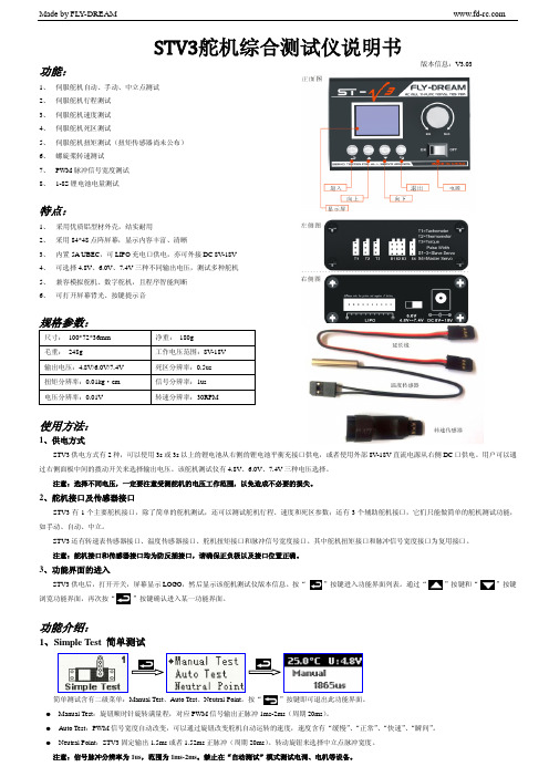
使用方法:
1、供电方式
STV3 供电方式有 2 种,可以使用 3s 或 3s 以上的锂电池从右侧的锂电池平衡充接口供电,或者使用外部 8V-18V 直流电源从右侧 DC 口供电。用户可以通 过右侧面板中间的拨动开关来选择输出电压。该舵机测试仪有 4.8V、6.0V、7.4V 三种电压选择。
将待测接收机通道与 STV3 的“T3”接口连接起来,按“ 可退出此功能界面。
8、1-8S Voltage 1-8S 电压测试
”按键进入测试界面。测试分辨率为 1us,测试范围为:100us-2500us。按“
”按键即
将待测电池插入右侧 LIPO 平衡充接口,按“ ”进入测试界面,测试精度为 0.01V。按“ ”按键即可退出此功能界面,进入功能界面浏览。
采用8448点阵屏幕显示内容丰富清晰内置5aubec可lipo充电口供电亦可外接dc8v18v可选择48v60v74v三种不同输出电压测试多种舵机可打开屏幕背光按键提示音规格参数
Made by FLY-DREAM
STV3舵机综合测试仪说明书
功能:
1、 伺服舵机自动、手动、中立点测试 2、 伺服舵机行程测试 3、 伺服舵机速度测试 4、 伺服舵机死区测试 5、 伺服舵机扭矩测试(脉冲信号宽度测试 8、 1-8S 锂电池电量测试
版本信息:V3.03
特点:
1、 采用优质铝型材外壳,结实耐用 2、 采用 84*48 点阵屏幕,显示内容丰富、清晰 3、 内置 5A UBEC,可 LIPO 充电口供电,亦可外接 DC 8V-18V 4、 可选择 4.8V、6.0V、7.4V 三种不同输出电压,测试多种舵机 5、 兼容模拟舵机、数字舵机,且程序智能判断 6、 可打开屏幕背光、按键提示音
EST3新版中文操作手册-大屏

E S T3中文版操作手册第一章基本系统操作概述本章叙述基本的系统操作指令内容面板控制显示信息处理显示开关的功能简介在本章所描述的操作系统中,必须确认每个事件。
每条信息可用“上一信息、下一信息”键查阅。
自动恢复(修复)的故障(Trouble)和状态(Monitor)等低优先权事件将被确认后自动地从信息队列中删去,而不必操作员按复位(Reset)键,系统即可恢复正常工作。
面板控制面板控制开关的功能或特点,其作用范围定义为,网络内当功能被激活时,火灾报警机箱受到影响的三种作用范围:•局部——其功能特性只影响安装了LCD显示屏的机箱•分组——其功能特性影响网络上预先定义好分组的机箱•全局——其功能特性影响网络上所有的机箱分组局部全局一个网络可以是一个或多个分组的一部分。
火灾报警系统配置的特性与功能因安装的不同而异,可根据现场的特殊情况,来决定是否已经把用户需要的功能与特点设计进去。
LCD显示屏LCD显示屏是系统的主要操作界面,它显示系统工作状态。
1.电源状态指示灯:当交流电源接通时绿灯亮。
2.测试状态指示灯:当系统的任何一部分处于测试状态时黄灯亮。
如果经过一段时间没有动作,可编程的定时器会自动退出测试模式。
3.系统故障指示灯:当中央处理器CPU的监视单元检测到处理器故障后,黄灯亮。
4.接地故障指示灯:当连接机箱的非接地线与地相连时黄灯亮。
5.屏蔽状态指示灯:当一些点或区域被人工屏蔽时黄灯亮。
6.自检状态指示灯:控制盘内部故障检测,当操作员控制系统自检按下此键时黄灯亮。
[3G R O U P.C D R]注意:此键可以另外编程,使其具有其他功能7. 盘消音键/指示灯:在所有事件被确认后,自动关闭控制盘内部蜂鸣声。
当蜂鸣器消音,以及控制盘处于非正常状态时黄灯亮。
按此键消音无效。
同时按下盘消音键和报警消音键将激活灯检测功能。
图 1-1 6.1寸LCD 显示屏3-LCDXL8. 显示屏:系统状态显示屏,带蓝色背光LCD 显示。
tennant v3 操作与零部件手册 - cn - 说明书 用户手册 使用指南

ENCanister Dry Vacuum Cleaner圆桶形干式真空吸尘器/manualsV3Model Part No.:型号部件编号:1070776 -V3 220-240V CN9009724Rev.00 (09-2012)Operator and Parts Manual 操作与零部件手册CNENGLISH 2Tennant V3 (09-2012)EN IntroductionThis manual is furnished with each new model. It provides necessary operation and maintenance instructions and replacement parts information.Read all instructions before using machine.Intended UseThis canister dry vacuum cleaner is suitable for picking up dray, non-flammable dust and debris in an indoorenvironment. It is not suitable for picking up liquids or hazardous materials.General InformationThis machine will provide excellent service. However, the best results will be obtained at minimum costs if: • The machine is operated with reasonable care.• The machine is maintained regularly - per the machine maintenance instructions provided.• The machine is maintained with manufacturer-supplied or equivalent parts.Protect the EnvironmentPlease dispose of packaging materials and used machine components in an environmentally safe way according to local waste disposal regulations. Always remember to recycle.Machine DataPlease fill out at time of installation for future reference. Model No. - Serial No. - Installation Date -Technical Specifications Model V3 Voltage 220-240V Frequency 50-60Hz Rated Power 1200W Airflow Rate 33 l/s Bag capacity 11 L Power Cord Length 12 m Weight 5.75 kg Size (Height x Width) 43cm x 37cm Sound Pressure Level************Construction Class II Vibrations at Controls <2.5 m/s2 Protection Grade IP20Tennant CompanyPO Box 1452, Minneapolis, MN 55440 USA Phone: (800) 553-8033 or (753) 513-2850 Tennant Cleaning Systems & Equipment Co., Ltd Building 1, No. 3777 Caoying Road Qingpu Shanghai, China 201712 phone: (86-21) 6922-53333 fax: (86-21) 6922-5151 Original Instructions. Copyright ©2012 Tennant Company. All rights reserved. Printed in China.Specifications and parts are subject to change without notice.IMPORTANT SAFETY INSTRUCTIONSThis symbol warns the operator of hazards and unsafe practices which could result in severe personal injury or death.WARNING - To reduce the risk of fire, electric shock, or injury:1. Do not leave appliance when plugged in.2. Unplug cord from outlet when not in use and beforeservicing.3. Do not use outdoors or on wet surfaces. This machine isfor indoor and dry use only.4. Do not allow to be used as a toy. Close attention isnecessary when used by or near children.5. Use only as described in this manual. Use onlymanufacturer's recommended attachments.6. Operators shall be adequately instructed on the use ofthis machine.7. This machine is not intended for use by persons(including children) with reduced physical, sensory or mental capabilities, or lack of experience and knowledge, unless they have been given supervision or instruction concerning use of the appliance by a person responsible for their safety.8. Do not use with damaged cord or plug. Regularly inspectcord and plug for damage. If the cord is damaged, it must be replaced by the manufacturer, its service agent or a similarly qualified person in order to avoid a hazard. 9. Do not pull or carry by cord, use cord as handle, close adoor on cord, or pull cord around sharp edges or corners. Do not run appliance over cord. Keep cord away from heated surfaces.10. Do not unplug by pulling on cord. To unplug, grasp theplug, not the cord.11. Do not handle plug or appliance with wet hands. 12. Connect to a properly grounded outlet only.13. Make sure the power voltage corresponds with thevoltage shown on the machine's rating plate.14. Do not put any object into openings. Do not use with anyopening blocked; keep free of dust, lint, hair, and anything that may reduce air flow.15. Keep hair, loose clothing, fingers, and all parts of bodyaway from openings and moving parts. 16. Turn off all controls before unplugging.17. Do not use to pick up flammable or combustible liquids,such as gasoline, or use in areas where they may be present.18. Do not pick up any type of fluid, hazardous dust or toxicmaterials.19. Do not pick up anything that is burning or smoking, suchas cigarettes, matches, or hot ashes. 20. Use extra care when cleaning on stairs.21. Do not use without dust bag and/or filters in place. 22. If using an extension cord make sure the cord rating issuitable for this machine.23. Do not modify machine from its original design.24. Keep children and unauthorized persons away from themachine when in use.25. All repairs must be performed by a qualified serviceperson. Use only manufacturer-supplied or equivalent replacement parts.26. Do not expose to rain or moisture. Store indoors only.SAVE THESE INSTRUCTIONSStorage and TransportingCarefully wrap power cord around machine's cord hooks and store machine in a dry indoor environment. Do not expose machine to rain or moisture. Lift machine by the carrying handle to transport.操作坦能V3 (09-2012)3CN介绍本手册提供各款最新型号的说明。
- 1、下载文档前请自行甄别文档内容的完整性,平台不提供额外的编辑、内容补充、找答案等附加服务。
- 2、"仅部分预览"的文档,不可在线预览部分如存在完整性等问题,可反馈申请退款(可完整预览的文档不适用该条件!)。
- 3、如文档侵犯您的权益,请联系客服反馈,我们会尽快为您处理(人工客服工作时间:9:00-18:30)。
将待测接收机通道与 STV3 的“T3”接口连接起来,按“ 可退出此功能界面。
8、1-8S Voltage 1-8S 电压测试
”按键进入测试界面。测试分辨率为 1us,测试范围为:100us-2500us。按“
”按键即
将待测电池插入右侧 LIPO 平衡充接口,按“ ”进入测试界面,测试精度为 0.01V。按“ ”按键即可退出此功能界面,进入功能界面浏览。
注意:信号脉冲分辨率为 1us,范围为 1ms-2ms。禁止在“自动测试”模式测试电调、电机等设备。
Made by FLY-DREAM
2、End Point 行程测试
在主舵机口 S4 插上待测舵机,行程测试能自动识别数字舵机和模拟舵机,从而进入相应的测试环节。行程测试的结果为左右极限对应的正脉冲宽度值, 单位为 us,可测范围为-180 度至 180 度。精度为 1us,另外为了形象的表示行程,我们也给出了脉冲宽度对应的角度值,单位为°,精度为 1°。按“ ” 按键即可退出此功能界面。
3、功能界面的进入
STV3 供电后,打开开关,屏幕显示 LOGO,然后显示该舵机测试仪版本信息。按“ ”按键进入功能界面列表。通过“ ”按键和“ ”按键 浏览功能界面,再次按“ ”按键确认ห้องสมุดไป่ตู้入某一功能界面。
功能介绍:
1、Simple Test 简单测试
简单测试含有二级菜单:Manual Test、Auto Test、Neutral Point。按“ ”按键即可退出此功能界面。 Manual Test:旋钮顺时针旋转满量程,对应 PWM 信号输出正脉冲 1ms-2ms(周期 20ms)。 Auto Test:PWM 信号宽度自动改变,可以通过旋钮改变舵机自动运转的速度,速度含有“缓慢”、“正常”、“快速”、“瞬间”。 Neutral Point:STV3 固定输出 1.5ms 或者 1.52ms 正脉冲(周期 20ms)。转动旋钮来选择中立点脉冲宽度。
注意:1、该运转速度包括舵机启动时间,有可能比某些舵机厂家标注的速度值大一些。 2、STV3 有三种电压档选择,请先选择好合适的电压档位,然后再连接舵机。以免舵机损坏,或者数值不准确。 3、如果需要测试另一款舵机需要退出,重新进入速度测试界面。
4、Dead Band 死区测试
在主舵机口 S4 插上待测舵机,然后按“ ”进入测试界面;旋转旋钮,选择待测试位置,选择好后,按“ 器短叫提示。死区测试分辨率为 0.5us。测试范围为:0.5us-25us。按“ ”按键即可退出此功能界面。
6、Tachometer 转速测试
将转速表插入 STV3 的“T1”接口,按“ ”进入测试界面,按“ 20cm 数据都有效,测试的范围为 0RPM-50000RPM,精度为 30RPM。按“
注意:因为此转速传感器采用光学器件,只适用于室外明亮环境。
7、Measure Pulse 脉冲宽度测试
”和“ ”选择桨的数量,STV3 还记录了此次测量的最大值。距离螺旋桨 ”按键即可退出此功能界面。
版本信息:V3.03
特点:
1、 采用优质铝型材外壳,结实耐用 2、 采用 84*48 点阵屏幕,显示内容丰富、清晰 3、 内置 5A UBEC,可 LIPO 充电口供电,亦可外接 DC 8V-18V 4、 可选择 4.8V、6.0V、7.4V 三种不同输出电压,测试多种舵机 5、 兼容模拟舵机、数字舵机,且程序智能判断 6、 可打开屏幕背光、按键提示音
注意:行程测试耗时数十秒,请耐心等候;角度值是基于脉冲宽度折算而来,且人为的认为中立点为 1.5ms,且为 0°。
3、Operate Speed 速度测试
在主舵机口 S4 插上待测舵机,通过 STV3 右侧拨动开关选择输出电压值,在不同电压下,舵机的运转速度不同。一般情况下,在固定电压范围内,电压越 高,舵机运转速度越快。STV3 测试出的舵机运转速度是从 666us 启动舵机,1833us 截止舵机,或者从 1833us 启动舵机,666us 截止舵机而得出的运转速度。 运转速度测试分辨率为 0.001s/60°。按“ ”按键即可退出此功能界面。
5、Torque Test 扭矩测试
”进入测试。测试结束后,STV3 蜂鸣
将待测舵机插在扭矩传感器上,然后固定好舵机和舵角,再将扭矩传感器“OUT”与 STV3 的“T3”接口连接起来,最后按扭矩传感器上的“START”按 键开始测试。扭矩测试的范围为 0kg·cm-20kg·cm,精度为 0.01kg·cm。测试结束后,传感器自动停止工作,STV3 上显示对应扭矩值。按“ ”按键即 可退出此功能界面。
规格参数:
尺寸: 100*72*36mm 毛重: 248g 输出电压:4.8V/6.0V/7.4V 扭矩分辨率:0.01kg·cm 电压分辨率:0.01V
净重: 180g 工作电压范围:8V-18V 死区分辨率:0.5us 信号分辨率:1us 转速分辨率:30RPM
使用方法:
1、供电方式
STV3 供电方式有 2 种,可以使用 3s 或 3s 以上的锂电池从右侧的锂电池平衡充接口供电,或者使用外部 8V-18V 直流电源从右侧 DC 口供电。用户可以通 过右侧面板中间的拨动开关来选择输出电压。该舵机测试仪有 4.8V、6.0V、7.4V 三种电压选择。
注意:选择不同电压,一定要注意受测舵机的电压工作范围,以免造成不必要的损失。
2、舵机接口及传感器接口
STV3 有 1 个主要舵机接口,除了简单的舵机测试,还可以测试舵机行程、速度和死区参数;还有 3 个辅助舵机接口,它们只能做简单的舵机测试功能, 如手动、自动、中立。
STV3 还有转速表传感器接口、温度传感器接口、舵机扭矩接口和脉冲信号宽度接口。其中舵机扭矩接口和脉冲信号宽度接口为复用接口。 注意:舵机接口和传感器接口均为防反插接口,请确保正负极以及接口位置正确。
9、其他:
同时按“ ”和“ ”2 个按键,打开屏幕背光;同时按“ ”和“ ”2 个按键打开按键音。
Made by FLY-DREAM
STV3舵机综合测试仪说明书
功能:
1、 伺服舵机自动、手动、中立点测试 2、 伺服舵机行程测试 3、 伺服舵机速度测试 4、 伺服舵机死区测试 5、 伺服舵机扭矩测试(扭矩传感器尚未公布) 6、 螺旋桨转速测试 7、 PWM 脉冲信号宽度测试 8、 1-8S 锂电池电量测试