DCS技术规格说明书
北京四方DCS系统硬件使用说明书_800S系列

2.2 控制器 ................................................................................................................................... 11 2.2.1 控制器技术参数 ............................................................................................................... 11 2.2.2 控制器功能 ....................................................................................................................... 11 2.2.3 指示灯含义 ....................................................................................................................... 12 2.2.4 跳线配置 ........................................................................................................................... 13 2.2.5 网络配置 ........................................................................................................................... 14 2.2.6 端子定义 ........................................................................................................................... 15 2.2.7 配置方法 ........................................................................................................................... 16
DCS-400E DCS-800E Quad Controller系列用户手册说明书
User ManualDCS-400EDCS-800EQuad Controller SeriesDocument Version: v1.3 7/12/21 Document Number: 1595-050167ContentsDCS-400E DCS-800E Quad Controller Series (1)Hardware Overview (3)DCS-400E, Quad Controller (3)DCS-800E, Quad Controller x2 (3)Installation Model (4)General Specifications (5)Front Panel (5)Front Panel Descriptions (8)Connector Information (10)Quick-Start (11)General Connection Diagram (11)Modes of Operation (12)Trigger Input & Outputs (13)Simplified Input Diagram (P2 pins 1 & 2) (13)Outputs – Frame Start/Stop (P2 pins 3 & 4) (13)Software Setup (14)Default Ethernet Settings (14)User Interface (GUI) (15)Software Usage (17)Overview (17)Software Modes (18)Standard Mode (18)Sequenced Mode (18)Network Configuration (19)Web Browser User Interface (20)Software Command and Control Interface (21)Command Structure (21)Command Table (22)Warranty Information (24)Customer Support and Product Information (24)Hardware OverviewThe DCS400 and DCS800 Quad Lighting Controller is a multi-channel controller for Advanced Illumination LED illuminators. With multi-channel control, this controller is ideal for applications such as photometric stereo, high-resolution color and bright-field / dark-field combination lighting.This controller family is not limited to computational imaging and can be used as a general-purpose controller for a wide range of applications in both continuous and strobe modes of operation.DCS-400E, Quad Controller Single Output, 4 ChannelsEthernet 10/100x2 digital trigger inputx2 trigger outputsDCS-800E, Quad Controller x2 Dual Output, 8 ChannelEthernet 10/100x2 digital trigger inputsx2 trigger outputsFigure 1 Figure 2Installation ModelFigure 3General Specifications*Values shown are based on controller component limitations. Actual limitations will vary depending on the limits set for the connected lighthead. These limits are determined using Advanced Illumination's proprietary SignaTechTM (Signature Technology) in order to ensure safe peak performance.** Various lighthead configurations available, including 1 x 4-channel quadrant (Q1) control or multiple single lightheads (Q4) per block.Front PanelDCS-400EFigure 4 DCS-800EFigure 5Refer to the tables on the next page for connection infoFront Panel DescriptionsTable 1 - Input Power, P1Pin Description Note124-48VDC Reverse polarity protected2 DC GNDTable 2 - Indicator LEDsColor Behavior FunctionLED 1Green On Main Power IndicatorLED 2Amber Heartbeat / Blink Flashes once per secondheartbeat while light is connected.Flashes when commands arereceived.LED 3Red Blink Code Error code—Long / Medium /Short flashes indicate an errorcodeTable 3 – IO Connector, P2Pin Description Note1TRIGGER-IN1ACTIVE-HIGH — pull high to activate(Channels 1-4)2TRIGGER-IN2ACTIVE-HIGH — pull high to activate(Channels 1-4 for DCS-400E, Channels5-8 for DCS-800E)3TRIGGER-OUT1Frame Start—output signal, occurs atthe beginning of each channel pulse 4TRIGGER-OUT2Frame Stop—output signal, occurs atthe end of each channel pulse 5TRIGGER GND Same as DC ground6TRIGGER GND Same as DC groundTable 4 – Output Connector P3 & P4Output 1 (P3) Output 2 (P4)Notes Pin Description Pin Description1SignaTech TM GND 9SignaTech TMGNDReserved2SignaTech TM 10SignaTech TM SignaTech TM LightProtection — NOT USERSERVICEABLE 3CH3 & CH4 - 11CH7 & CH8 -LED Cathode (common)* 4CH4 + 12CH8 +LED Anode5CH3 + 13CH7 +LED Anode6CH1 & CH2 - 14CH5 & CH6 -LED Cathode (common)* 7CH2 + 15CH6 +LED Anode8CH1 + 16CH5 +LED Anode Important Information*LED Cathode pins, pin 1 and pin 9 are COMMON and may be tied together.This controller requires SignaTech to operate correctly. SignaTech is included with lights purchased from Advanced Illumination. It is not possible to drive a non-SignaTech protected light source without explicit instruction from Advanced Illumination.Connector InformationPower Input (P1)Phoenix Contact, 1748354, 18-24 AWGTrigger Input (P2)Phoenix Contact, 1881367, 22-26 AWGLight Output (P3, P4)Plug: Phoenix Contact, 1827761Strain Relief: Phoenix Contact, 1834408, 18-24 AWGQuick-StartGeneral Connection DiagramNOTE; Trigger 2 and Light 2 only apply to DCS800* Figure 6 – General Wiring ExampleModes of OperationContinuousEach channel is capable of up to 1A output in standard mode. Continuous mode is not possible in sequence mode; in sequence mode, DC can be simulated by using long pulse widths.Note: Depending on the load and power dissipation, not all channels may operate at 1A simultaneous. The controller must maintain a safe power dissipation, so channel currents may be throttled.Each channel has an operating power limit of 10W, so the controller may throttle the power depending on the load that is connected.PulsedPulsed mode illumination is triggered by an external signal.Pulse widths and delay are available from 10 to 4,290,000000 microseconds and can be applied independently to any channel.Note: Trigger Input 1 and Trigger Input 2 are for Outputs 1 and 2 respectivelySequenceChannels settings are organized into events. The event could be considered a pre-set, or recipe, that stores the behavior when a trigger is received.Programming multiple events allows the controller to sequence through pre-determined recipes. Each external trigger edge will advance the sequence to the next event.Standard vs. SequencedStandard mode acts like a traditional strobe controller, where all channels that are enabled are triggered at the same time.Sequenced makes each trigger signal progress the saved sequence once event at a time.Trigger Input & OutputsSimplified Input Diagram (P2 pins 1 & 2)Outputs – Frame Start/Stop (P2 pins 3 & 4)Frame-start (Pin 3) is a 5V output trigger signal that occurs at the beginning of each channel pulse. This signal can be used to trigger an external device, or camera.For example: by using the frame-start signal, it is possible to synchronize a camera exposure to capture each channel as they flash in a sequence. This is useful inphotometric stereo applications where the camera needs to be carefully synchronized to capture multiple flashesFrame Stop (pin 4) -- Similar to frame-start except the stop signal begins at the end of each light pulse. This signal can be used to determine when the last channel pulse has ended and is useful for controlling system timing more accurately.Figure 5 Figure 6Software SetupDefault Ethernet SettingsThe Controller uses standard Ethernet protocol (TCP-IP and UDP) to communicate. The DCS control user interface can be used to communicate, or other software may be used to send data packets directly from the host to the controller.Table 5Setting ValueTypical Port Settings UDP, port 7777TCP, port 777DHCP Enabled by defaultDefault IP Address 192.168.0.5*Controller will use default IP if DHCP fails upon powerup, or if an Ethernet cable is not connectedUser Assigned IP Addresses User can assign a new IP address by sending acommand or entering a new IP address in the “managedevices” window of the GUI.If a user assigned IP address is used, the controller willnot begin using that IP address until the controllerpower is toggled.Figure 7 - Example PC settings This controller uses DHCP to automatically acquirean IP address. If directly to a PC Ethernet port, youwill need to set up the PC to use a static IP addressin the range of 192.168.0.xUser Interface (GUI)Figure 8 – Control GUITable 6 – Control GUI functionsSoftware Item DescriptionFile Save and Load recipes to the controllerDevice Additional options, clear saved settingsRefresh Re-scans the network for devicesConnect Connects to the device highlighted in the dropdownNetwork Configuration Edit and view network settings for the connected deviceEvents Contains all the channel settings (current, pulse width, delay, etc.)Add Event Creates a new blank event to be configured by the userDelete Event Removes the event from the listSave all events Commits the events to controller memory and saves changesLoad event sets the focused event as “active”Trigger Simulates a hardware trigger, activating the focused eventStop Stops all channels. Useful if the pulse or delays are set to very longvalues and must be interruptedEvent name Rename the focused eventSequenced Enables sequenced modeSequences List of sequences saved to the controllerAdd Sequence Creates a new sequenceSet Sequence Active Sets this sequence to be the actively triggered sequenceTrigger Sequence Simulates a hardware trigger, triggers the sequence one event at a time(does not trigger the entire sequence at once)Stop Sequence Halts the sequence, stopping any long channel pulses or delays Selected Sequence Choose the sequence to view or editAdd Event to Sequence Adds the selected event in the dropdown to the sequence. Event canthen be arranged in any orderSoftware UsageOverviewThe Ai DCS-400/800 software must connect to a device before it can be used. The Refresh button (see Figure 9) refreshes the list of available DCS-400/800 devices on the local network. Either select a device from the list or type an IP address (in dotted-quad, e.g. “XXX.XXX.XXX.XXX” format) and click connect.Figure 9: Software main window exampleSoftware ModesStandard ModeThe standard mode allows using a DCS-400 or DCS-800 like a traditional 4- or 8-channel controller. Operation in Standard Mode starts by putting the controller in Standard Mode and adding an Event (See Error! Reference source not found.).Adding an EventOnce an event is added, you can set configurations (current, channel mode, etc.) on each channel and they will be immediately reflected on the controller. Note that the event itself is not auto-saved: if you power down the controller the configuration will be lost unless you click “Save all Events”. The warning shown in Figure will inform you if you have unsaved edits.Figure 10Other events you add must be loaded with the Load Event button to be applied to the device. Loading an Event will set that Event active on the device, and it will be auto-loaded next time the device is powered on. If no Event is loaded when the device is power cycled, it will load the first available saved Event. Saving channel configurations as an Event allows you to easily recall the configurations later, much like the Profiles in Advanced illumination’s DCS-100 and DCS-103 controllers.Sequenced ModeSequenced mode allows the controller to automatically cycle through a predefined series of Events with a hardware trigger (currently only Trigger Input 1). This allows the controller to, for example, flash alternate sides of a right light with only one a continual stream of trigger pulses and no further input from the software/SDK.EventsCreating an Event is the same as in Standard Mode, except for two points:1.Event changes are not immediately updated on the device.2.An Event cannot be loaded directly while in Sequenced Mode, only Sequences can.SequencesA Sequence is, at its simplest, a list of Events. When a Sequence is loaded, a hardware trigger causes the controller to start the first Event in the list, the next trigger starts the next event, and so on. When the last Event in the Sequence is reached, it starts over from the first Event.Clicking “Add Sequence” adds a new sequence, which appears inline below the other sequences in the list. On any Sequence, you can select an Event from the dropdown in the Sequence and click “Add selected event” to add that event to the Sequence. You can have multiple of the same Event in the Sequence; however, you are limited to 10 Events per sequence.Once you have a Sequence defined, click “Save sequences” to save all defined Sequences to the controller. You can then make load a Sequence on the controller by clicking “Set as active” on a sequence. The “Run sequence” button allows you to simulate a trigger pulse to ensure that sequence is working as intended. Be aware that this button sends an HTTP POST message to the controller, so there will be network delay between the click and the pulse.Network ConfigurationNetwork Configurations are viewed by clicking the “Network Configuration” button on the main window when connected to a device. Network Configurations opens in its own window, as shown in Figure 7 below.Figure 73: Network Configuration example in DHCP ModeStatic IP configurationA static IP address is set by entering an IP address, subnet mask, and Gateway address in the boxes provided. Note that the window displays the current value of all settings, even if it’s using DHCP. Settings are saved by clicking the “Save Settings” button. If settings are saved unchanged from the values displayed from DHCP, then the device is assigned a static IP address configuration matching those values.Resetting to DHCPNetwork configuration can be reset back to DHCP mode by clicking the red text “Reset to DHCP” button, which will replace the green DHCP message when the device is using a static address. The device should then be power cycled for it to use its new settings.Web Browser User InterfaceEntering the device IP address into a web browser (Chrome, Firefox, Edge) will open the controller web browser.Figure 14Software Command and Control InterfaceCommand StructureThe DCS400/800 uses an SCPI-like interface where commands are a series of readable strings with parameters separated by commas. The strings must be terminated by a semicolon (‘;’) for proper operation.Commands can be sent in an ASCII format by specifying the IP Address and correct port number for either TCP/IP or UDP.Commands with a parameterCommands that require a parameter have it separated by a comma.Example: “SET:PULSE:WIDTH:CHANNEL1, 100;”Where “SET:PULSE:WIDTH:CHANNEL1,” is the command and “100” is the parameter. Commands without a parameterIf the command has no parameter, the command simply ends with a semicolon.Example: “*IDN?;”Commands are case sensitive, and must be entered exactly as shownCommand TableTable 7COMMAND DESCRIPTION RETURNSSET:CURRENT:CHANNELc,nnnn;Sets the current inmilliampsc = 1 - 8 (channelnumber)nnnn= 0-8000 (strobe)SET:PULSE:WIDTH:CHANNELc,nnnn;Sets the pulsewidth in usecc = 1 - 8 (channel number)nnnn = 0 – 4290000000 (us)INFO: Channel “c” pulse width set to “nnnn” usSET:PULSE:DELAY:CHANNELc,nnnn;Sets the pulse delay inusecc = 1 - 8 (channel number)nnnn = 0– 4290000000 (us)INFO: Channel “c” pulsedelay set to “n”microseconds.PULSE:CHANNELc;Software triggers thechannelc = 1-8SET:MODE, [SEQUENCED][STANDARD];Sets the controller ineither sequence (mode 0) orstandard (mode 1)Note: can use the number 0or 1 instead of “sequenced”or “standard” in thecommandINFO: Set mode to 'n'SAVE:CONFIG,[1-10]Saves the active channelsettings to the given eventnumber (standard mode only)*IDN?;Gets device information: firmware, hardware, etc..Advanced illumination“DCS-100: (fw version, hw version)”*CHANNEL:INFO?;Gets device channelinformationSET:IP:ADDRESS,xxx;Sets static IP address.Xxx = IP address in dotted-quad format(XXX.XXX.XXX.XXX)INFO: Set IP address to XXX.XXX.XXX.XXX. Reboot for it to take effect.SET:GATEWAY:ADDRESS,xxx;Sets gateway IP address.Xxx = IP address in dotted-quad format(XXX.XXX.XXX.XXX)INFO: Set Gateway address toXXX.XXX.XXX.XXX. Reboot for it to take effect.SET:SUBNET:MASK,xxx;Sets subnet mask.Xxx = subnet mask indotted-quad format(XXX.XXX.XXX.XXX)INFO: Set subnet mask to XXX.XXX.XXX.XXXERASE:SETTINGS;Erases device settings.STOP:SEQUENCE;Stops running sequence.Immediately aborts alllong-running pulses andshuts off all : Running sequence abortedRUN:SEQUENCE;Runs the currently activesequence. Imitates ahardware trigger insequenced : Running event X on Sequence XX is event/sequence numberWarranty InformationEvery Advanced illumination, Inc. (Ai) product is thoroughly inspected and tested before leaving the factory. Products are warranted to be free of defects in workmanship and materials for a period of five years from the original date of purchase. Should a defect develop during this period, please contact Ai Customer Service or your Ai distributor for a Return Merchandise Authorization (RMA), and return the complete product, freight prepaid, to Ai. Please provide a detailed description of the problem if possible. If a defect is found, Ai will - at our discretion - repair or replace the product without charge. Ai claims no liability for any implied warranties, including “merchantability” and “fitness for a specific purpose.”Customer Support and Product InformationStandard Product Information: Customer Service Inquiries: ****************************************440 State Garage Road, Rochester VT. 05767© 2019 Advanced Illumination Inc. All rights reserved。
杭州四方称重系统有限公司 DCS-30型车辆动态称量自动衡器 使用说明书

DCS-30型车辆动态称重自动衡器使用说明书杭州四方称重系统有限公司二〇一〇年三月目录一.系统构成及功能 (1)1.系统构成 (1)2.主要技术指标 (2)二.安装条件 (2)三.工作原理 (2)四.控制仪表面板和外部电路连接 (4)五.使用方法 (6)六.调试 (7)七.通讯协议 (7)八.保养和维护 (9)九.售后服务 (10)一.系统构成及功能1.系统构成DCS-30型车辆动态称重自动衡器是对行驶中的车辆进行称重的自动化称重设备, 特别适用于目前高速称重和计重收费系统。
整个系统由机械称重台面、传感器系统、轮轴识别器、红外车辆分离器、称重显示器等组成,与之配套的设施有秤体基础及控制室等。
机械称重台面安装在基础之上,重物放置在台面上或按一定的速度通过称重台面,称重台面将重力传递给传感器,传感器完成力/电转换,输出电信号,经称重仪表处理,完成模拟/数字转换、数据采集、处理、显示及打印制表等工作。
①机械称重台面机械称重台面作为支撑与传力机构,由秤台、传感器压头、纵向限位、横向限位、底座及基础预埋板等组成,完成计量过程的导向、支撑与力的传递工作。
秤台是秤的主体部分,由型钢和钢板焊接而成,具有足够的强度、刚度和良好的稳定性。
秤台通过传感器安装在基础预埋件之上。
根据现场使用情况,可选择不同尺寸的秤台,或者双秤台结构。
传感器压头是传感器与秤台的连接件,它的作用是保证传感器的受力状态良好。
底座的作用是支撑称重传感器和限位系统,它与基础预埋板焊接固定。
预埋板预埋在钢筋混凝土基础中,作为底座支撑。
②传感器系统传感器系统由一组称重传感器和接线盒组成, 传感器连接方式为全并联方式。
DCS电子衡单台使用4只传感器, 双秤台为8只传感器,通过接线盒与称重显示器相连,并调节衡器四角平衡。
③轮轴识别器本公司自行设计开发,并取得专利,能自动识别车辆的轴型与车轮。
④红外车辆分离器能自动判断车辆是否整车通过,从而准确判断整车重量。
DCS使用说明书
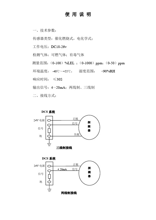
使 用 说 明一、技术参数:传感器类型:催化燃烧式,电化学式;工作电压:DC18-26v检测气体:可燃气体;有毒气体测量范围:(0-100)%LEL ;(0-1000)ppm ;(0-50)ppm环境温度: -40℃~+55℃; 湿度范围: <90%RH响应时间: ≤30S输出信号:4~20mA ;两线制、三线制二、接线方式:DCS 系统24V 电源信号 地 三线制接线24V 电源信号 地 两线制接线DCS 系统对于DCS系统三线制最大消耗电流≤200mA,将探测器的正极与DCS系统的电源24V对接,负极与DCS系统地对接,信号与DCS 系统的信号对接产生4-20mA;对于DCS系统两线制最大消耗电流≤30mA,将探测器的正极与DCS系统的电源24V对接,负极与DCS 系统的信号对接产生4-20mA。
列:通入标气为20%LEL测的的电流应为:16mA * 20%LEL = X * 100%LELX = 3.2mA因基准电流为4mA,通气20LEL%对应的电流为3.2mA,则显示电流应为:4mA+3.2mA=7.2mA,测量的结果为7.2mA.三、安装位置:探测器安装在被检测气体易漏场所,且安装位置根据被检测气体相对于空气比重大小决定。
当被检测气体比重大于空气比重时,探测器应安装在距离地面30-60cm处,且传感器部位向上,当被检测气体比重小于空气比重时,探测器应安装在距离顶棚30-60cm处。
且传感器部位向下,为了正确使用探测器及防止探测器故障的发生,请不要安装在以下位置:1、直接受蒸气、油烟影响的地方。
2、给气口、换气扇、房门等风量流动大的地方。
3、水气、水滴多的地方(相对湿度:≥90%RH)。
4、温度在-40℃以下或55℃以上的地方。
5、有强电磁场的地方。
北京四方DCS系统硬件使用说明书_800S系列
1 概述.................................................................................................................................................. 1
2.2 控制器 ................................................................................................................................... 11 2.2.1 控制器技术参数 ............................................................................................................... 11 2.2.2 控制器功能 ....................................................................................................................... 11 2.2.3 指示灯含义 ....................................................................................................................... 12 2.2.4 跳线配置 ........................................................................................................................... 13 2.2.5 网络配置 ........................................................................................................................... 14 2.2.6 端子定义 ........................................................................................................................... 15 2.2.7 配置方法 ........................................................................................................................... 16
锅炉房 DCS 系统配置 说明书

Tel:021-********锅炉房DCS系统配置二00七年七月二十六日目录一、 工程情况二、 分散控制系统(DCS)的监视控制范围三、 DCS的技术要求四、 DCS的硬件要求五、 DCS的软件要求六、 备品备件和专用工具七、 工程服务八、 图纸和文件九、 培训十、 其他要求、说明一、 工程情况:1.1 我处拟建设1台DZL4-1.25-AⅡ蒸汽锅炉和4台(先期2台)4SZL14-1.0/115/70—AⅡ热水锅炉及其辅助设备、除氧给水、采暖循环泵等。
1.2 蒸汽锅炉采用DZL4-1.25-AⅡ锅炉。
主要技术参数:额定蒸发量 4 t/h;额定过热蒸汽压力 1.25MPa;额定过热蒸汽温度400℃;给水温度105℃;1.3热水锅炉采用4SZL14-1.0/115/70—AⅡ锅炉。
主要技术参数:额定蒸发量20 t/h;额定过热蒸汽压力 1.0MPa;额定热水温度115℃;给水温度70℃;二、主厂房分散控制系统(DCS)的监视控制范围2.1 主厂房DCS监视控制范围包括3台锅炉等主设备及其热力系统中的所有辅助设备。
即包括锅炉、送风机和引风机系统、除氧给水系统、采暖循环泵系统等辅助设备。
三、分散控制系统(DCS)的技术要求3.1 总的要求:3.1.1 DCS采用进口DCS系统。
3.1.2 DCS应具有数据采集(DAS)、模拟量控制(MCS)、顺序控制(SCS)、等功能,以满足各种运行工况的要求,确保机组安全、高效运行。
3.1.3 DCS应由分散处理单元、数据通讯系统和人机接口组成。
3.1.4 DCS系统应易于组态、易于使用、易于扩展。
3.1.5 DCS的设计应采用合适的冗余配置和诊断至模件级的自诊断系统.使其具有高度的可靠性。
系统内任一组件发生故障时,不影响整个系统的工作。
3.1.6 系统的参数、报警、和自诊断功能应高度集中在CRT上显示和在打印机上打印,控制系统应在功能上适当分散。
3.1.7 DCS应采取有效措施,防止各类计算机病毒的侵害和DCS内各存储器的数据丢失。
ABBDCS500B_DCF500BDCS600_DCF600直流传动技术数据说明书

9.1 附 件 - 功 率 元 件 ....................................................................................... III 9-1 9.2 附 件 - 励 磁 部 分 ....................................................................................... III 9-4 9.3 附件- 风扇, 控制部分 .............................................................................. III 9-5
4 电 源 供 电 板 ....................................................................... III 4-1
4.1 SDCS-POW-1 ........................................................................................... III 4-1
DCS 500 晶 闸 管 变 流 器 直流传动系统 25-5150A 技术数据
DCS 500B/DCF 500B DCS 600/DCF 600
内容提要
III 技术数据
1 快 速 指 导 ............................................................................ III 1-1
新版MDCS-I使用说明书
目次1 系统概况 (1)2 系统主要功能 (2)2.1分站功能 (2)2.2主站(控制台)功能 (2)2.3系统其它功能 (3)3 系统组成 (3)4 主要技术参数 (6)4.1系统容量 (6)4.2分站技术参数 (6)4.3主站(控制台)技术参数 (8)4.4分线盒 (8)4.5多功能控制柜 (8)4.6总线电缆技术参数 (8)5 使用说明 (10)5.1分站使用说明 (10)5.2主站(控制台)使用说明 (11)5.3系统数据设置及管理 (13)6 常见故障及处理方法 (15)MDCS-I无主机共线型全数字指令扩音呼叫/对讲系统技术说明书1、系统概况MDCS-I无主机共线型全数字指令扩音呼叫系统是一种集广播呼叫、程控交换、调度指挥功能为一体的多功能生产管理通信系统,其主要特点为:1)无主机总线控制方式,分散功率放大器,系统可靠性高;2)共线型网络结构,布线方便;全系统共用一根电缆,连接在同一根电缆上的所有分站(室内型、室外型)及主站(控制台)都可随时发起或接收呼叫,互不影响,呼叫控制灵活。
3)具有普通程控交换机及调度机功能;系统中所有分站或主站(控制台)都可随时通过拨号方式呼叫另一分站(或控制台),组成全双工通话方式。
4)一根电缆上最多可有5对(10部)分站同时进行全双工通话。
5)系统中所有室外型分站都外接一扬声器,实现广播呼叫。
6)分站或主站(控制台)都具有点呼、选呼、追呼、组呼、全呼功能;主站(控制台)具有强插、强拆、监听、单/双向控制、通话录/放音等多种功能。
7)具有会议功能;三方以上的通话自动进入会议模式,会议各方均可自由发言。
8)可与外部的程控交换机、调度机等通信设备联网。
9)可与外部的计算机及其它数据端口联网。
10)可通过扩音广播方式,向全系统各站发送多种告警信号。
11)系统安装简单,扩充方便,只需从就近的电缆分线即可增加新的分站。
12)室外型分站外壳采用抗静电增强聚酯材料制成(IP65等级), 可安装于任何恶劣环境。
- 1、下载文档前请自行甄别文档内容的完整性,平台不提供额外的编辑、内容补充、找答案等附加服务。
- 2、"仅部分预览"的文档,不可在线预览部分如存在完整性等问题,可反馈申请退款(可完整预览的文档不适用该条件!)。
- 3、如文档侵犯您的权益,请联系客服反馈,我们会尽快为您处理(人工客服工作时间:9:00-18:30)。
D C S技术规格说明书目录1.概述 (2)2.DCS控制规模 (3)3.系统功能要求 (3)4.系统设计 (5)5.技术要求 (8)6.技术服务及培训 (8)1.概述1.1范围本规格书概括了湖北新洋丰肥业股份有限公司S-NPK厂DCS系统改造工程的分散型控制系统(Distributed control system;简称DCS)的各项要求,内容包括DCS的基本技术条件、制造、质量保证、培训等各阶段的要求。
1.2标准规范1.2.1除另有说明外,提供的系统应满足以下认证,并符合相应规范和国家标准的最新版本:IEC、ISO和制造厂标准CE认证符合UL、CSA、FM、 DIV2安全规程要求其他:ANSI/ISA S5.1 仪表符号和说明ISA S5.4 仪表回路图ISA S5.3 DCS系统图形符号IEEE802.31.3系统特点1.3.1系统采用分布式结构,在开放式的以太网络上分布了多台系统组件,这些系统组件带有独立的功能处理器,并能进行设备和功能的扩展。
1.3.2用于现场控制的集成控制器将实现整个过程系统的数据采集、混合模拟量和开关量过程控制和批量处理、时序控制等应用要求并采用功能模块化的组态工具进行编程。
用于过程监视及管理的人-机接口单元即操作站其显示、操作、记录、管理等则功能集中。
该系统将在生产装置内经过现场调试、配上电源、接上输入输出信号就可满足本装置的生产监视、过程控制、操作画面、参数报警、数据记录及趋势等项的功能要求。
1.3.3系统组成1.3.3.1集成控制器通过过程I/O硬件、连接端子及必要的信号隔离处理,完成连续的、离散的数据采集功能,过程控制器将集中在全厂中央控制室。
1.3.3.2作为人-机接口的CRT操作站包括键盘、打印机、彩色图形显示器等安装在中央控制室。
1.3.3.3工程师站是由彩色CRT、键盘、打印机、磁盘驱动器等组成的,可与操作员站共用。
1.3.3.4系统组件(集成控制器、操作员)之间通过10MB的TCP/IP以太网络进行通讯,以太网络支持集成控制器之间点对点的通信。
集成控制器应具有多种通信接口,如以太网络接口、RS232接口、RS485接口等。
1.4供货方责任范围1.4.1指派一名项目经理在整个项目执行期间与买方进行主要联系,在项目执行期间,该项目经理应为同一人。
1.4.2提供的DCS应能完全满足本规格书所要求的硬件和软件功能。
1.4.3对其DCS系统提出优化配置方案及系统工程,系统配置图、设备/组件清单、电源消耗、电路保护、接地要求等。
1.4.4负责完成全部系统的配置,提供配置方案,并得到采购方的确认。
在DCS制造厂完成全部设备包括硬件和软件的检查和测试。
1.4.5提供系统组态的全过程支持。
1.4.6设备包装后运至装置现场。
1.4.7现场服务包括设备开箱验收、现场安装、回路检查、开车等。
1.4.8在DCS制造厂对采购方仪表维护人员、系统工程师进行有关课程培训。
1.4.9有义务召开本项目的协调会,在项目进行过程中接受采购方的监督和询问。
1.4.10按照本规格书的要求提供全部文件和资料。
2.DCS控制规模2.1输入/输出信号类型DCS的过程控制器应能直接接收或处理以下各种类型的输入和输出信号:2.1.1模拟量输入2.1.1.1模件为智能化模件,可万能输入,通道与通道之间隔离,隔离电压为400VDC 2.1.1.2可直接输入T/C、 mV 、V、RTD、mA等信号,并可设置断线保护2.1.1.3精度为量程范围的±0.1%,模/数转换精度为15bit2.1.2数字量输入2.1.2.1标准的数字量(AC、DC)2.1.2.2干节点信号2.1.3模拟量输出2.1.3.14~20mA. DC电流信号2.1.3.2通道与通道之间隔离,隔离电压为500VDC2.1.3.3负载为0~750欧姆2.1.3.4精度为量程的0.1%2.1.4数字量输出2.1.4.1开关量输出24VDC. 0.5A/点2.2输入/输出信号规模详见表A:系统规模数据3.系统功能要求3.1控制功能集成控制器可以实现连续的和离散的功能,每个集成控制器至少能处理512个输入输出点、32个控制回路,具有多种类型的功能模块,具有在线编程和修改的能力。
3.1.1连续控制集成控制器可以完成基本的调节和先进的控制,控制器至少应提供以下功能块算法:⏹各种PID控制(如单回路、串级、比值等)⏹平方/开方/加/减/乘/除等运算⏹流量补偿和累计⏹超前/滞后⏹延时⏹高/中/低选择⏹变化率限制⏹累积计量、平均值⏹模拟量变换(SCALE)⏹报警类型:H, HH, L, LL, Rate of change, deviation3.1.2离散控制功能在离散控制中至少应提供以下功能块算法:⏹开关控制⏹与、或、非逻辑⏹输入、输出反向⏹计数/计时⏹离散设备控制(主要用于对泵的控制)⏹交替设备控制3.1.3系统监视⏹系统启动和运行状态监视⏹输入输出机架监视3.2监控软件监控软件安装在操作站上,用于工艺流程显示、操作、管理、记录、报表、报警等,监控软件应具有开放的人机接口,可以与大多数世界著名厂家生产的DCS、PLC、记录仪、调节器等进行通讯,监控软件应支持Hart、Profibus、Modbus、RS232/422/485、Ethernet、TCP/IP等多种通讯协议,并支持动态数据交换如ODBC、DDE、OLE等,以便与其他系统或软件实现双向通讯和数据交换。
监控软件应采用图形化组态方式,能方便生成系统总貌、分组、细目、趋势、报警、报表等图形画面。
监控软件的操作界面应为全汉化。
3.2.1.1总貌画面显示系统各设备、装置、区域的运行状态以及全部过程参数变量的状态、测量值、设定值、控制方式(手动/自动状态)、高低报警等信息。
从各显示块可以调出其他画面。
3.2.1.2分组画面以模拟仪表的表盘形式按事先设定的分组,同时显示几个回路的信息:如过程参数变量的测量值、调节器的设定值、输出值、控制方式等。
变量值每秒更新一次,分组可任意进行,操作员可从分组画面调出任一变量(模拟量或离散量)的详细信息。
对模拟回路可以手动改变设定值、输出值、控制方式等;对离散量可以手动操作设备的开启和停止,画面显示出指令状态和实际状态。
3.2.1.3趋势画面3.2.1.3.1系统具有显示任何数据点趋势的能力,并在同一座标轴上显示至少六个变量的趋势记录曲线,有可供采购方自由选择的参数变量、不同颜色和不同的时间间隔,也可以对数据轴进行任意放大显示。
3.2.1.3.2具有实时和历史趋势显示和记录3.2.1.4报警画面显示当前所有正在进行的过程参数报警和系统硬件故障报警,并按报警的时间顺序从最新发生的报警开始排起,报警优先级别和状态用不同的颜色来区别,未经确认的报警处于闪烁状态。
3.2.1.5报警内容包括:3.2.1.5.1报警时间3.2.1.5.2过程变量名3.2.1.5.3过程变量说明3.2.1.5.4过程变量的当前值3.2.1.5.5报警设定值3.2.1.5.6过程变量的工程单位3.2.1.5.7报警优先级别3.2.1.6图形画面生产装置的工艺流程图、设备简图、单线图等都可以在CRT上显示出来,通常采用可变化的颜色、图形、闪烁表示过程变量的不同状态,所有过程变量的数值和状态每秒动态刷新。
操作员在此画面对有关过程变量实施操作和调整。
3.2.1.7棒图棒图可以表示过程变量的变化,如棒图表示塔的液位,棒图能以水平或垂直方式显示。
3.3报警功能3.3.1当报警发生时,系统将具有以下动作:3.3.1.1系统将根据报警的级别和设置实时打印当前的报警内容,报警内容见3.2.1.5 3.3.1.2同时系统产生声响报警,并提供报警颜色的变化,用以提示操作者3.3.2报警类型至少具有下列类型:3.3.2.1高报3.3.2.2低报3.3.2.3高高报3.3.2.4低低报3.3.2.5偏差报3.4报表功能3.4.1DCS按照预先定义的格式打印报表,报表数据的收集和打印是按照采购方定义的时间间隔自动或手动进行,报表打印通常采用事件驱动方式或操作员命令方式,报表软件将自动产生所有的标题和表头。
3.4.2可以提供日报表、班报表、月报表3.4.2.1可以实现随时、定时打印报表功能3.5历史数据存储功能3.5.1DCS应对报警、联锁、操作指令的变化等事件及其日期、时间作为历史数据加以储存。
3.5.2应有足够的能记录半年以上历史数据的磁介质存储空间,并具有可扩充至外部存储设备。
3.5.3应提供历史报表、历史趋势功能。
3.6组态功能3.6.1应提供一个任务集成并且符合IEC 1131标准的组态工具3.6.2应具有FBD(功能块)、SFC组态能力3.6.3具有在线帮助能力3.6.4具有丰富、灵活的作图能力3.6.5具有仿真调试的能力4.系统设计4. 1 设计原则4.1.1DCS是由以微处理器为基础的、分散式的多台系统组件所组成,这些系统组件分布在具有开放式结构的以太网络上,包括:操作员站、控制和数据采集系统、外设及有关的硬件和软件。
4.1.2系统是经过试验的高可靠性的,并且是出厂前最新的硬件和软件版本。
4.1.3通讯系统是高可靠的,即单台硬件设备出现故障(包括通讯系统硬件故障)都不会影响其它系统组件之间的通讯。
4.1.4系统允许在不关闭系统的情况下在线更换系统模件或组件,允许带电插拔。
4.1.5系统中的任何组件通电或掉电都不会影响其它组件的运行。
4.1.6联锁系统故障检出元件动作时,在操作站的CRT显示屏上应进行声光报警,同时报警打印机立即打印出来,并贮存在历史模件中,报警的确认和消声由键盘或按钮来实现。
4.2操作站4.2.1概述4.2.1.1操作站是操作员了解各装置全部信息的接口单元,操作员可在正常或异常情况下对各装置进行控制和监视。
4.2.1.2操作系统应为WINDOWS NT或XP系统的最新可靠运行版本。
4.2.1.3操作站的功能如下:4.2.1.3.1显示全部的过程变量及有关参数4.2.1.3.2操作所有控制回路的参数,如改变设定点、工作方式、回路输出、调整PID参数等4.2.1.3.3报警显示4.2.1.3.4过程流程图显示4.2.1.3.5趋势显示(实时的和历史的)4.2.1.3.6报告和报表4.2.1.3.7系统诊断报告4.2.2支持功能DCS操作站应能支持通用的编程软件,以帮助采购方维护和修改数据库、编制应用程序。
支持功能包括在线和离线的数据库定义(即组态、下载等)、备份(即拷贝、定期存贮到软盘等)、文件/程序管理等。
4.2.3基本硬件4.2.3.1操作站主要由彩色显示器、键盘、鼠标器、中央处理单元等组成,同时可以支持各种外部设备如打印机、拷贝机、磁带机等。