HT Specifications
ht7550中文资料_数据手册_参数
Production stops After this specified date no more devices will be manufactured and last deliveries made. At this point the device can be said to have reached their end of life status.
H T75X X
. ro n t V ie w
V O U T G N D V IN
B o tto m V ie w
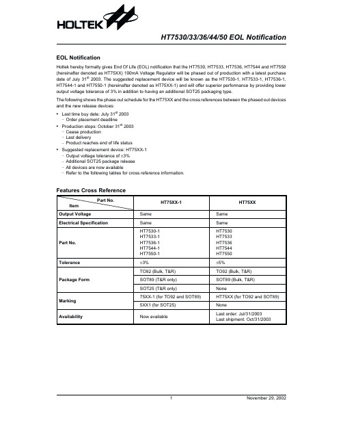
HT75XX Output Voltage
3.0V±5% 3.3V±5% 3.6V±5% 4.4V±5% 5.0V±5%
Order No./ Marking
HT7530 HT7533 HT7536 HT7544 HT7550
HT7530/33/36/44/50 EOL Notification
EOL Notification
Holtek hereby formally gives End Of Life (EOL) notification that the HT7530, HT7533, HT7536, HT7544 and HT7550 (hereinafter denoted as HT75XX) 100mA Voltage Regulator will be phased out of production with a latest purchase date of July 31st 2003. The suggested replacement device will be known as the HT7530-1, HT7533-1, HT7536-1, HT7544-1 and HT7550-1 (hereinafter denoted as HT75XX-1) and will offer superior performance by providing lower output voltage tolerance of 3% in addition to having an additional SOT25 packaging type.
Cannondale Scalpel HT自行车所有者手册补充说明书

READ THIS SUPPLEMENT AND YOUR CANNONDALE BICYCLE OWNER’S MANUAL. Both contain important safety information. Keep both for future reference.Safety MessagesIn this supplement, particularly important informationis presented in the following ways:SYMBOLS:= Apply NLGI-2 Synthetic grease or a high-quality bicycle bearinggrease= Apply Carbon Gel, Friction Paste for bicycle components= Apply Loctite® 242, or medium strength removable thread lock N·m = Tightening torque in Newton meters.CONTENTSSafety Information ...........................2-7Technical Information ....................8-17Replacement Parts .............................18Maintenance .. (19)Cannondale SupplementsThis manual is a “supplement” to your Cannondale Bicycle Owner’s Manual. This supplement provides additional andimportant model specific safety, maintenance, and technical information. It may be one of several important manuals/supplements for your bike; obtain and read all of them.Please contact your Authorized Cannondale Dealer immediately if you need a manual orsupplement or have a question about your bike. You may also contact us using the appropriate country/region/location information.You can download Adobe Acrobat PDF versions of any manual/supplement from our website: .Contacting CannondaleCannondale USACycling Sports Group, Inc. 1 Cannondale Way Wilton, CT 06897, USA 1-800-726-BIKE (2453)CSG Europe (Woudenberg)Cycling Sports Group Europe B.V. Geeresteinselaan 57 3931JB Woudenberg The NetherlandsPH: 00.31.541.200374International DistributorsConsult our website to identify the appropriate Cannondale Dealer for your region.Your Cannondale DealerTo make sure your bike is serviced and maintained correctly, and that you protect applicable warranties, please coordinate all service and maintenance through yourAuthorized Cannondale Dealer.Scalpel HT OMSSafety InformationImportant Composites MessageSafety InformationImportant CompositesMessageInspection & Crash DamageOf Carbon Frames/ForksSafety InformationIntended UseServicingIntended UseThe intended use of all models is ASTM CONDITION 3,Cross-Country.Tightening TorquesCorrect tightening torque for the fasteners (bolts, screws, nuts) on your bicycle is very important to your safety. Correct tightening torque for the fasteners is also important for the durability and performance of your bicycle. We urge you to have your dealer correctly torque all fasteners using a torque wrench. If you decide to torque fasteners yourself always use a torque wrench.Find Tightening Torque Information :Scalpel HT OMSSafety InformationMaximum Fork LengthMaximum Fork LengthMaximum Fork Length is an important frame safety testing specification for front suspension mountain bikes. You must observe the measurement when installing headset parts, headsetadapters, installing and adjusting a fork, and selecting replacement forks.To Center Of The Fork AxleSafety Information Tire Size x Maximum Width12Serial NumberThe serial number is located on the bottom bracket. It is a 7-character barcode (1). Use this serial number to register your bike.To register your bike: go to theProduct Registration section ofour website atScalpel HT OMSSafety Information Minimum Seat Post Insert - FrameMinimum Seat Post Insert - FrameTechnical InformationSpecificationsTechnical InformationAll Specifications subject to change without notice.SpecificationsScalpel HT OMSTechnical Information Geometry - Scalpel HT 100 (Lefty Ocho)Geometry - Scalpel HT 100 (Lefty Ocho)Specifications subject to change without notice.Technical InformationGeometry - Scalpel HT 110 (Lefty Ocho 120)Geometry - Scalpel HT 110 (Lefty Ocho 120)Specifications subject to change without notice.Scalpel HT OMSSeat PostInstallation & AdjustmentBefore installing: •To ensure good clamping and avoid creaking, remove all residual carbon paste with a clean cloth dampened with rubbing alcohol. Wipe the inside of the seat tube and seat post. Wipe again using a clean area of the cloth and repeat until the cloth comes away clean.• Apply fresh carbon friction paste to the seat post and place a little bit inside the seat tube. •Lightly grease the seat tube under the seat post clamp.To adjust:1.Insert the prepared seat post into the frame.2. Set the saddle height. Maintain the specifiedminimum insert.3.Tighten the binder screw to the specified torque.Minimum InsertThe minimum insert depth the seat post must be inserted into the frame is 100mm.Maximum InsertThe total length of seat post that may be inserted will vary with the frame size and should be checked in each frame.To check, carefully slide a seat post into the frameuntil it stops; then lift it up 5mm.For more information about carbon fiber seatposts, see also “Care and Maintenance of Carbon Fiber Seat Posts” in your Cannondale Bicycle Owner’s Manual.35 N·m12N G LI -2C R B -G E L100mm5mmIdentificationSeat postSeat post clamp Clamp boltThreaded insertMinimumMaximum Bottom OutApply carbon paste to entire length of the inserted seat postScalpel HT OMSChain Guide SetupTo install the chain guide:1. Clean the guide and the frame mountinglocation.2. Attach the guide arm to the frame with themounting screw. Tighten to 1-2 Nm with atorque wrench/To set the position of the chain guide: 1. Shift the chain onto the largest cog on therear cassette.2. Positon the flat surface of the chain guidehead 1mm above the chain as shown nextfigure. The pointed end faces forward on the bike.3. Place a 1mm allen key flat on top of the chainso its flat side contact the chain and theguide lower surface and lower the chainguide into the allen key, then tighten to2-3 Nm.4. Test to confirm the chain guide is operatingproperly by pulling the chain towards theoutside of a slowly rotating chain , attemptingto derail the chain, while pedaling it forward(by hand) in the work stand. The chain should not come off of the guide. If the chain doescome off of the guide, slightly lower the guideuntil it does not.5. Confirm the chain guide does not rub whilethe rider is pedaling the bike in the largestcassette cog.c b. recessc. point end1mm21. Frame BB Shell2. Bearing Cup3. Housing cover, drive side4. Mechanical cable guide,drive side5. Brake housing cover,non-drive sideIdentificationClean surface and apply Loctite® 680 retaining compound, ensure that both mating surfaces of the cup are completely covered before pressing in the PF30 cups. Allow time to cure ac-cording to Loctite instruction prior to proceeding with bearing installation. below:Technical InformationUniversal Derailleur Hanger (UDH)Universal Derailleur Hanger (UDH)1aReplacementBefore installing a new /replacement hanger, be sure to clean any dirt or debris on the dropout with a nylon brush (e.g., old toothbrush). Inspect the area for any damage especially after a crash or impact. Take corrective action when required. Use a good-quality torque wrench and tighten to the specified torque.1. UDH dropout2. UDH hanger3. UDH washer4. UDH Bolta. UDH rotation stopIdentificationDPRD RBTechnical InformationGuards/Protectors - PlacementGuards/Protectors - Placement2Scalpel HT OMSReplacement Parts.Replacement PartsFGJHA19MaintenanceDeveloping an ScheduleMaintenanceThe following table lists only supplemental maintenance items. Please consult your Cannondale Bicycle Owner’s Manual for more information on basic bike maintenance.Developing an ScheduleCANNONDALE USA Cycling Sports Group, Inc.1 Cannondale Way, Wilton CT, 06897, USA 1-800-726-BIKE (2453) CSG EUROPECycling Sports Group Europe B.V.Geeresteinselaan 573931JB WoudenbergThe Netherlands******************************CANNONDALE UKCycling Sports GroupVantage Way, The Fulcrum,Poole, Dorset, BH12 4NU+44 (0)1202732288***************************.uk。
SPECIFICATIONS 产品说明书

SPEC19-08 10/15)Outlet: 1-1/4” tube outlet for 1-1/4” slip joint connectionACCESS PANELSHeavy-gauge steel with vandal-resistant screws. Provides access for easy hook-up of all plumbing connections. SUGGESTED SPECIFICATIONSUnit shall include powder-coated finish with vandal-resistant pushbutton actuation, vandal-resistant bubbler with integral hood guard, and contour-formed rounded basin to reduce splash and prevent standing water. Fountain shall comply with ANSI 117:1 and ADA for visual and motion disabilities. The manufacturer shall certify the unit to meet the requirements of NSF/ANSI 61, and the Safe Drinking Water Act.Outdoor TubularModel LK4410FRK is shown.2222 Camden Court Oak Brook, IL In keeping with our policy of continuing product improvement, Elkay reserves the right to change specification without notice. Please visit for the most current version.ModelColor OptionADA CompliantNSF/ANSI 61CertifiedLK4410FRK*(Refer to Finish Color Options)••* Select color option to complete model number. Example: LK4410FRK EVG Beige Black Blue Brown Evergreen GrayOrange Purple Terracotta Red White YellowN o w Av a i l a bl ei n12Co l o r s !Each 4410 FR consists of 2 cartons of the following:• Fountain• Single Freeze-Resistant Valve System - 97243CThis specification describes an Elkay product with design, quality and functional benefits to the user. When making a comparison of other producer’s offerings, be certain these features are not overlooked.FINISH COLOR OPTIONS – Choose color option to complete your model number, add as suffix example: LK4410FRK EVGMatte finish: Evergreen = EVG Gloss finish: Beige = BGE Gray = GRY Terracotta = TER Black = BLK Orange = ORN White = WHT Blue = BLU Purple = PUR Yellow = YLWBrown = BRN Red = REDOPTIONS• Hose Bib (Locking) - LK4471LHB * (Choose color option to complete your model number)• Hose Bib (Non-Locking) - LK4470NLHB* (Choose coloroption to complete your model number)• Direct Bury Kit - 97890CPrinted in the U.S.A.Page 2MODEL LK4410FRK Outdoor TubularFreeze-Resistant FountainOPERATING PRESSURES:Supply water 20 – 105 psi maximumMOUNTING INSTRUCTIONS and PLUMBING INSTRUCTIONSSite and drainage excavation is required for fountain installation. Refer to owner’s manual for site preparation details. Provide solid, well-drained surface to mount pedestal fountain (concrete pad recommended) with adequate support (300 lb. load minimum). (6) 3/8” minimum fasteners (not included) should be attached securely to mounting surface in order to secure fountain, (Refer to rough-in diagram), and be sure to allow an opening for the freeze-resistant valve in the ground as shown in the diagram below). Refer to local codes for any additional requirements.Locate and install plumbing through ground as required. Assemble fountain to prepared site and mounting pad.NOTE: Fountain is not furnished with service valve.Position pedestal over plumbing and secure base to fasteners. Remove access panels and connect supply and water lines. Turn on water supply and check for leaks. Refer to owner’s manual for detailed instructions.Reassemble access panels to pedestal. Trap and service stop not included.2222 Camden Court Oak Brook, IL 。
京东方HT150X02-100型工业用屏幕说明书
1.0 GENERAL DESCRIPTION 1.1 Introduction1.3 Application2.0 ABSOLUTE MAXIMUM RATINGSThe followings are maximum values which, if exceed, may cause faulty operation or3.0 ELECTRICAL SPECIFICATIONS 3.1Electrical Specifications4.0 OPTICAL SPECIFICATION4.1 OverviewNote :5.0INTERFACE CONNECTION.5.1 Electrical Interface Connection5.2 LVDS Interface (Tx; THC63LVDF83A or Equivalent)6.0 SIGNAL TIMING SPECIFICATION6.1 The HT150X02-100 is operated by the DE & H-Sync & V-Sync mode ( LVDS Transmitter Input )6.2 LVDS Rx Interface Timing ParameterThe specification of the LVDS Rx interface timing parameter is7.0 SIGNAL TIMING WAVEFORMS OF INTERFACE SIGNAL7.1 Sync Timing Waveforms7.3 Horizontal Timing Waveforms8.0 INPUT SIGNALS, BASIC DISPLAY COLORS & GRAY SCALE OF COLORS9.0 POWER SEQUENCETo prevent a latch-up or DC operation of the LCD module, the power on/off sequence10.0 MECHANICAL CHARACTERISTICS10.1 Dimensional Requirements11.0 RELIABLITY TESTPRODUCT GROUPTFT- LCD PRODUCTREV P0ISSUE DATE 2006.01.1712.0 HANDLING & CAUTIONS(1) Cautions when taking out the module Pick the pouch only, when taking out module from a shipping package. (2) Cautions for handling the module As the electrostatic discharges may break the LCD module, handle the LCD module with care. Peel a protection sheet off from the LCD panel surface as slowly as possible. As the LCD panel and back - light element are made from fragile glass material, impulse and pressure to the LCD module should be avoided. As the surface of the polarizer is very soft and easily scratched, use a soft dry cloth without chemicals for cleaning. Do not pull the interface connector in or out while the LCD module is operating. Put the module display side down on a flat horizontal plane. Handle connectors and cables with care. (3) Cautions for the operation When the module is operating, do not lose CLK, ENAB signals. If any one of these signals is lost, the LCD panel would be damaged. Obey the supply voltage sequence. If wrong sequence is applied, the module would be damaged. (4) Cautions for the atmosphere Dew drop atmosphere should be avoided. Do not store and/or operate the LCD module in a high temperature and/or humidity atmosphere. Storage in an electro-conductive polymer packing pouch and under relatively low temperature atmosphere is recommended. (5) Cautions for the module characteristics Do not apply fixed pattern data signal to the LCD module at product aging. Applying fixed pattern for a long time may cause image sticking. (6) Other cautions Do not disassemble and/or re-assemble LCD module. Do not re-adjust variable resistor or switch etc. When returning the module for repair or etc., Please pack the module not to be broken. We recommend to use the original shipping packages.SPEC. NUMBER B2006-C001-O(3/3)SPEC. TITLE HT150X02-100 Preliminary Product SpecificationPAGE 21 OF 28 A4(210 X 297)PRODUCT GROUPTFT- LCD PRODUCTREV P0ISSUE DATE 2006.01.1713.0 PRODUCT SERIAL NUMBERSPEC. NUMBER B2006-C001-O(3/3)SPEC. TITLE HT150X02-100 Preliminary Product SpecificationPAGE 22 OF 28 A4(210 X 297)PRODUCT GROUPTFT- LCD PRODUCTREV P0ISSUE DATE 2006.01.1714.0 Packing14.1 Packing OrderPut pads into the box.As shown in figure, place Modules bundled shielding bag in box.the the by theAfter sealing the box, attach Packing Label on the attach position sign area of the box.Place a cover on the top of the box.SPEC. NUMBER B2006-C001-O(3/3)SPEC. TITLE HT150X02-100 Preliminary Product SpecificationPAGE 23 OF 28 A4(210 X 297)PRODUCT GROUPTFT- LCD PRODUCTREV P0ISSUE DATE 2006.01.1714.2 Packing Note Box Dimension : 333mm(W) × 333mm(D) × 435mm(H) Package Quantity in one Box : 8pcs 14.3 Box label Label Size : 108 mm (L) × 56 mm (W) Contents Model : HT150X02 Q`ty : Module Q`ty in one box Serial No. : Box Serial No. See next page for detail description. Date : Packing Date FG Code : FG Code of ProductHT150X02- ### 00000000000008 2006.04.30.00 Type0 0 00 0 Grade Line Year Month0 00000 ITEM-CODE Serial_noFG CODESPEC. NUMBER B2006-C001-O(3/3)SPEC. TITLE HT150X02-100 Preliminary Product SpecificationPAGE 24 OF 28 A4(210 X 297)PRODUCT GROUPTFT- LCD PRODUCTREV P0ISSUE DATE 2006.01.1715.0 APPENDIXFigure 1. Measurement Set Up(L = 50cm )Figure 2. White Luminance and Uniformity Measurement Locations (5 points)102 512 92276384692SPEC. NUMBER B2006-C001-O(3/3)SPEC. TITLE HT150X02-100 Preliminary Product SpecificationPAGE 25 OF 28 A4(210 X 297)PRODUCT GROUPTFT- LCD PRODUCT Figure 3. Response Time TestingDisplay data White(TFT OFF) TR Optical Response 100% 90% Black(TFT ON)REV P0ISSUE DATE 2006.01.17White(TFT OFF) TF10% 0% TimeFigure 4. Cross Modulation Test DescriptionVIEW AREA VIEW AREA256,192 768,192 L31 256,576 768,576 YA (896,384) YB - YA YA L0 YB(896, 384)Cross-Talk (%) =× 100Where: YA = Initial luminance of measured area (cd/m2) YB = Subsequent luminance of measured area (cd/m2) The location measured will be exactly the same in both patternsSPEC. NUMBER B2006-C001-O(3/3)SPEC. TITLE HT150X02-100 Preliminary Product SpecificationPAGE 26 OF 28 A4(210 X 297)PRODUCT GROUPTFT- LCD PRODUCTREV P0ISSUE DATE 2006.01.17Figure 5. TFT-LCD Module Outline Dimensions (Front view)SPEC. NUMBER B2006-C001-O(3/3)SPEC. TITLE HT150X02-100 Preliminary Product SpecificationPAGE 27 OF 28 A4(210 X 297)PRODUCT GROUPTFT- LCD PRODUCTREV P0ISSUE DATE 2006.01.17Figure 6. TFT-LCD Module Outline Dimensions (Rear view)SPEC. NUMBER B2006-C001-O(3/3)SPEC. TITLE HT150X02-100 Preliminary Product SpecificationPAGE 28 OF 28 A4(210 X 297)。
CommScope HT3580H系列四密度全谱宽频分布多路复用(DWDM)发射器系统说明书
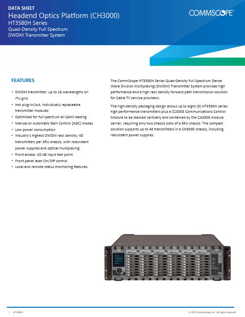
DATA SHEETHeadend Optics Platform (CH3000)HT3580H SeriesQuad-Density Full Spectrum DWDM Transmitter SystemThe CommScope HT3580H Series Quad ‐Density Full Spectrum Dense Wave Division Multiplexing (DWDM) Transmitter System provides high performance and a high rack density forward path transmission solution for Cable TV service providers.The high ‐density packaging design allows up to eight (8) HT3580H series high performance transmitters plus a CC3008 Communications Control Module to be stacked vertically and contained by the CA3008 module carrier, requiring only two chassis slots of a 3RU chassis. The compact solution supports up to 48 transmitters in a CH3000 chassis, including redundant power supplies.•DWDM transmitter: up to 16 wavelengths on ITU grid•Hot plug ‐in/out, individually replaceable transmitter modules•Optimized for full spectrum all QAM loading •Manual or Automatic Gain Control (AGC) modes •Low power consumption•Industry’s highest DWDM rack density: 48 transmitters per 3RU chassis, with redundant power supplies and optical multiplexing •Front access ‐20 dB input test point •Front panel laser On/Off control•Local and remote status monitoring featuresFEATURESWhen installed in the chassis, the transmitters interface to a “zero ‐slot” back plate, providing support for up to eight HT3580H series transmitters. The figure below shows a fully loaded carrier mated to the BD31A8 Quad ‐Density back plate that supports eight HT3580H transmitters.The CC3008 Communications Module installed at the top of a HT3580H series transmitter stack provides the communications interface between the transmitters and the CH3000 mid ‐plane bus, allowing complete configuration and management control of the stack, both local andremote.HT3580H Series Quad ‐Stack and CC3008 Communications Module in CA3008 module carrier joined with a BD31A8 Back PlateHT3580H Series Quad ‐Density Full Spectrum DWDM Transmitters (1.2 GHz Passband)CommScope HT3580H Series Quad ‐Density Full Spectrum DWDM Transmitters are a key element of the CommScope HFC and Fiber Deep architectures in support of the evolution to all QAM transmission. These high ‐performance transmitters are designed for Dense Wave Division Multiplexing (DWDM) applications for point ‐to ‐point forward path transmission of full spectrum broadcast and narrowcast services.HT358xH series transmitters are designed for all QAM loading. These transmitters also incorporate advanced dispersion compensation circuitry to enable transmission of high ‐quality signals over maximum distances.The above figure shows a front view of the CA3008 carrier components: a single HT358xH Quad ‐Density Transmitter (left); a single CC3008 Communications Module (right), and a fully loaded “stack” (center) providing eight (8) DWDM transmitters, requiring only 2 slots of a CH3000 Chassis. A fully loaded CH3000 chassis supports 48 Quad ‐Density DWDM transmitters and redundant power supplies.Features•DWDM transmitter: 16 wavelengths on the ITU grid •Manual or Automatic Gain Control (AGC) modes •RF input attenuation up to ‐6 dB •Optimized for full spectrum loading •HT358xH: All QAM loading•Hot plug ‐in/out, individually insertable•Low power consumption•Industry’s highest DWDM rack density: 48 transmitters per 3RU chassis, with redundant power supplies •Front access ‐20 dB input test point •Front panel laser On/Off interlock control •Local and remote status monitoringHT3580H SERIES SPECIFICATIONSPhysicalDimensions11.5” D x 0.4” H x 2.0” W (29.2 x 1.0 x 5.1 cm)*Weight0.4 lb(0.18 kg)* Eight (8) transmitter units designed to be vertically stacked, plus a CC3008 Communications Module, and installedinside a CA3008 Module Carrier. The combination occupies two slots in a 3RU CH3000 Chassis.EnvironmentalOperating‐20°to +50°C (‐4°to 122°F)Storage‐40°to +85°C (‐40°to +185°F)Humidity5% to 95% non‐condensingRF and Optical InterfacesRF Input F‐type male (located on BD31A8 or BD35M8 Back Plates)RF Test Point75Ω MCX female (located on front panel) MCX male to F female adapter provided with each Quad BD3 back plate.Additional adapters available in packs of ten, order P/N TL3MCXF‐10Optical Connector SC/APC (located on BD35M8 Back Plates)LC/APC (located on BD31A8 Back Plates)Power RequirementsInput Voltage12 VDCPower Consumption6 W (per transmitter) including controller and back plate cooling fanGeneralHot plug‐in/outManual and automatic gain controlChannel LoadingHT358xH: All QAM channelsOpticalOptical Output Power10 ±0.25 dBmWavelength See DWDM ITU Channel Plans descriptionFiber Length60 km max. (Dispersion Compensation adjustable in 1 km steps)•Compatible with external dispersion compensation for some applicationsElectricalPassband45 to 1218 MHzFrequency Response (Including Slope)•±1.0 dB (BC input @ 25°C)•±0.5 dB (NC input relative to BC input)NOTE: NC QAM signals are attenuated 6 dB before internal combining with BCanalog signalsNominal RF Input Levels (Input Attenuator = 0 dB)Broadcast (BC) RF input: 10.2 dBmV 194 256‐QAM channelsNarrowcast (NC) RF input: 16.2 dBmV 194 256‐QAM channelsRF Input Impedance75 Ω, nomRF Input Return Loss18 dB, minRF Input Attenuator/Amplify Range (Manual Mode)‐6.0 to 0 dBRF Input Attenuator Step Size0.5 dBAGC Mode Maintains RF power constant when input RF power changes up to ±3 dB of the learned RF valueLevel Stability (Typical)±0.2 dB256‐QAM BER< 10–6(pre‐FEC, ITU‐C)MER (194 QAM load)40 (40 km), 37 (60 km)DWDM ITU Channel PlansSee muxing back plate information for wavelength graphics. CommScope supports DWDM network architectureswith a variety of products on the standard DWDM ITU Grid (ITU‐T G.694.1). For a more complete description, pleaserefer to the CommScope DWDM ITU Grid Channel Plan data sheet.BD31A8‐100 Quad ‐Density Back PlatesThe BD31A8 models provide RF input and optical connections to or from the HT358xH transmitters. The fan provides air flow to keep transmitters cool.BD31A8‐100‐H10F ‐0‐AL is a quad ‐density back plate that provides 1 common BC input and 8 separate NC RF inputs for eightHT358xH Transmitters. It also supports eight separate optical output LC/APC connectors. Internally it includes an RF amplifier and splitter to split the BC input equally to all 8 transmitters and maintain 1x8 RF levels.BD31A8‐100‐H18F ‐0‐AL is a quad ‐density back plate that provides 8 separate BC inputs and 0 NC RF input for eight HT358xH Transmitters. It also supports eight separate optical output LC/APC connectors. This back plate is recommended for customers that prefer to do their broadcast and narrowcast RF combining external from the CH3000 Chassis.BD31A8‐100‐H10F ‐0‐AL Back Plate CA3008 Module CarrierBD31A8 BACK PLATE SPECIFICATIONSSpecificationPhysical Dimensions 7.2” D x 5.2” H x 2.0” W (18.2 x 13.0x 5.4cm)Weight 2.0 lb (0.91 kg)Environmental Operating ‐20°to +65°C (‐4°to 149°F)Storage ‐40°to +85°C (‐40°to +185°F)Humidity5% to 95% non ‐condensingPower Requirements Input Voltage 12 V DCPower Consumption 5.5 W max (2.5 W Typ),included in power figure found in HT3580H specifications OpticalThrough 8 LC/APC connectors, the BD31A8‐100 provides optical pass ‐through from the HT358xH transmitter.Optical Insertion Loss 0.2 dB Typ; 0.3 dB Max RF InterfaceThe BD31A8 provides RF to the HT358xH transmitter through F ‐type RF connectors.•1 BC and 8 NC (BD31A8‐100‐H10F ‐0‐AL)•8 BC and 0 NC (BD31A8‐100‐H18F ‐0‐AL)BD35M8‐ACx and BD35M8‐EEx Quad‐Density Back Plates for Groups of 8 WavelengthsThe CommScope BD35M8 Family of back plates are 100 GHz grid spacing Quad‐Density Mux Back Plates that multiplex the output of eight HT3580H Quad‐Density Full Spectrum Transmitters.These back plates provide connections for a group of eight HT3580H Series Transmitters installed in the same CA3008 Module Carrier, along with the CC3008 Communications Control Module.These 8‐channel mux back plates (for which outputs can be cascaded from one back plate to another) may be ordered for the channel groups indicated in the ordering information section.BD35M8 BACK PLATE SPECIFICATIONSPhysicalDimensions7.2” D x 5.2” H x 2.0” W (18.2 x 13.0x 5.4cm)Weight 2.0 lb(0.91 kg)EnvironmentalOperating‐20°to +65°C (‐4°to 149°F)Storage‐40°to +85°C (‐40°to +185°F)Humidity5% to 95% non‐condensingPower RequirementsInput Voltage12 V DCPower Consumption5 W max (2.5 W Typ), included in power figure found in HT3580H specificationsOptical InterfaceOptical Connectors SC/APC (3)•DWDM INP (input from previous mux back plate)•DWDM OUT (output to network or next mux back plate)•‐20 dB optical test pointRF Interface9 F‐Type Connectors•1 BC and 8 NCOpticalChannel Spacing100 GHzChannel Plan See ITU Channels in Ordering InformationInsertion Losses, Including ConnectorsTyp Max•DWDM Input to DWDM Output 1.8 dB 2.1 dB•Ch. yy Input to DWDM Output 2.0 dB 2.4 dB•‐20 dB Test Point 20.0 dB 20.4 dBUniformity, Including Connectors•Module Uniformity 1.1 dB 1.5 dB•Paired Uniformity0.5 dB0.7 dBReturn Loss, min45 dBDirectivity, min55 dBPassband @ 0.2 dB•Ch. yy Input to DWDM Output±0.125 nm•DWDM Input to DWDM Output Passes 1423.5 through 1617.5 with a notch at the channel add/drop band. WDL for the passband is within ±0.15 dB Polarization Dependent Loss, max0.15 dB (typically < 0.05 dB)Power Handling, max (Any Input Port)21.8 dBmBD35M8‐DCx Quad‐Density Back Plates for 2 Sets for the Same Group of 4 WavelengthsThe CommScope BD35M8 Family of back plates are 100 GHz grid spacing Quad‐Density Mux Back Plates that multiplex the output of 2 sets of four HT3580H Quad‐Density Full Spectrum Transmitters onto two separate output ports.These back plates allow 2 sets of four HT3580H Series Transmitters installed in the same CA3008 Module Carrier, and using the same CC3008 Communications Control Module, to feed two different fibers with four wavelengths on each fiber.These 2x4‐channel mux back plates (for which outputs can be cascaded from one back plate to another) that may be ordered for the channel groups indicated in the ordering information section.BD35M8 BACK PLATE SPECIFICATIONSPhysicalDimensions7.2” D x 5.2” H x 2.0” W (18.2 x 13.0x 5.4cm)Weight 2.0 lb(0.91 kg)EnvironmentalOperating‐20°to +65°C (‐4°to 149°F)Storage‐40°to +85°C (‐40°to +185°F)Humidity5% to 95% non‐condensingPower RequirementsInput Voltage12 V DCPower Consumption5 W max (2.5 W Typ), included in power figure found in HT3580H specificationsOptical InterfaceOptical Connectors LC/APC (6)•2 of DWDM INP (input from previous mux back plate)•2 of DWDM OUT (output to network or next mux back plate)•2 of ‐20 dB optical test pointRF Interface9 F‐Type Connectors•1 BC and 8 NCOpticalChannel Spacing100 GHzChannel Plan See ITU Channels in Ordering InformationInsertion Losses, Including ConnectorsTyp Max•DWDM Input to DWDM Output 1.1 dB 1.3 dB•Ch. yy Input to DWDM Output 1.3 dB 1.5 dB•‐20 dB Test Point 20.0 dB 20.4 dBUniformity, Including Connectors•Module Uniformity0.4 dB0.5 dB•Paired Uniformity0.5 dB0.7 dBReturn Loss, min45 dBDirectivity, min55 dBPassband @ 0.2 dB•Ch. yy Input to DWDM Output±0.125 nm•DWDM Input to DWDM Output Passes 1423.5 through 1617.5 with a notch at the channel add/drop band. WDL for the passband is within ±0.15 dB Polarization Dependent Loss, max0.1 dB (typically < 0.05 dB)Power Handling, max (Any Input Port)21.8 dBmH T 358*H –Q –***0–2–A SQuad ‐Density, Full Spectrum DWDM Transmitter (1.2 GHz)3 = EEx Wavelengths (See BD35M8 Table Below)4 = ACx Wavelengths (See BD35M8 Table Below)For HT3583H = E + ** ITU Channel #For HT3584H = A + ** ITU Channel #** = ITU Channel Number (20 through 62;See CommScope DWDM ITU Grid Channel Plan Data Sheet)Connector Type: SC/APCHT358xH TransmitterConnector Type: SC/APCBack PlatesB D 31A 8–100–H 1x F –0–A LB D 35M 8–***–H 20F –3–A SHT3584H16 Wavelength Plan Code Wavelength Group AC2ITU CH 20, 21, 24, 29ITU CH 35, 42, 52, 54AC4ITU CH 23, 33, 44, 47ITU CH 51, 57, 58, 59HT3583H16 Wavelength Plan Code Wavelength Group EEBITU CH 21, 22, 24, 26ITU CH 28, 33, 36, 39EED ITU CH 44, 48, 52, 54ITU CH 57,60, 61,62Quad ‐Density Back Plate for 8 HT358x Full Spectrum Transmitters with LC/APC Connector 0 = 1 Common BC Input and 8 NC RF Inputs 8 = 8 BC Inputs and 0 NC RF Input Connector Type: LC/APCQuad ‐Density Muxing Back Plate for 8 HT358x Full Spectrum Transmitters with SC/APC Connectors with Optical Test Point0 = 1 Common BC Input and 8 NC RF InputsConnector Type: LC/APCB D 35M 8–D **–H 20F –3–A LHT3584H 2 sets of 4 of the 16 Wavelength Plan Code Wavelength Group DC1ITU CH 20, 21, 24, 29ITU CH 20, 21, 24, 29Quad ‐Density Muxing Back Plate for 2 Sets of 4 of the HT358x Full Spectrum Transmitters with LC/APC Connectors with Optical Test Point 0 = 1 Common BC Input and 8 NC RF InputsSystem AccessoriesContact Customer Care for product information and sales:•United States: 866‐36‐ARRIS •International: +1‐678‐473‐5656RELATED PRODUCTSCH3000 Chassis Optical Patch Cords Optical Transmitters Optical Passives Digital ReturnInstallation ServicesNote: Specifications are subject to change without notice.Copyright Statement:©2022CommScope,Inc.All rights reserved.ARRIS and the ARRIS logo are trademarks of CommScope,Inc.and/or its affiliates.All other trademarks are the property of their respective owners.No part of this content may be reproduced in any form or by any means or used to make any derivative work (such as translation,transformation,or adaptation)without writtenpermission from CommScope,Inc and/orits affiliates (“CommScope”).CommScope reserves the right to revise or change this content from time to time without obligation on the part of CommScope to provide notification of such revision or change.C C 3008Communications Control ModuleC A 3008Module CarrierH T 3F I L HFiller Module for Quad ‐Density Slots。
Phoenix 200HT 安装、操作和维护说明说明书

Owner’s Manual — Phoenix 200HT Installation, Operation & Service InstructionsPhoenix 200HT4029970Specifications subject to change without notice.TS-621 02/154201 Lien Rd.• Madison, WI 53704The Phoenix 200HT is one of the most effective and versatile drying devices available. The Phoenix 200HT features higher capacity and superior efficiency compared to other refrigerant dehumidifiers, removing 135 pints per day at AHAM while drawing only 7.2 amps of electricity.The 200HT also features Phoenix’s patented bypass system. At higher temperatures, where typical LGRs lose effectiveness, patented Bypass Technology helps the Phoenix 200HT continue to remove moisture, leading to faster evaporation, quicker drying, and elimination of the need to remove equipment for temperature control./user/usephoenix1 SpecificationsPart No.4029970Power110-120 Vac, 7.2 ampsWater 135 pints/day @ AHAM (80°F, 60%)RemovalRefrigerant 2 lbs. 2 oz. R410aChargeBlower380 CFMInternal Condensate Pump with 20’ lift,30’ vinyl hoseOperating 33°F to 125°FRangeFilters16” x 20” x 2” Pleated Media MERV-11Duct Intake – 12” Flex-DuctOptions Exhaust – 10” Lay-FlatWarranty Five years;First year 100% of Parts and LaborSecond-fifth year 100% of Parts of sealedrefrigeration system.Dimensions Width 20”, Height 40”, Depth 23”Weight 130 lbs.2 Operation2.1 Transporting the Phoenix 200HTThe Phoenix 200HT must always be upright whentransported by vehicle. It may be tipped on to its handle andback for loading and moving by hand.2.2 LocationNote the following precautions when locating the Phoenix200HT:• It is designed to be used INDOORS ONLY.• If used in a wet area, plug it into a GROUND FAULTINTERRUPTER.• DO NOT use the Phoenix 200HT as a bench or table.• It must always be used in the upright position.• The air inlet on top & the side outlet must be at least1 foot from walls and other obstructions to air flow. Table of Contents Introduction (1)1. Specifications (2)2. Operation (2)2.1 Transporting the Phoenix 200HT (2)2.2 Location (2)2.3 Electrical Requirements (3)2.4 Condensate Removal (3)2.5 Ducting (3)2.6 Power Button (3)2.7 Pump Purge Button (3)2.8 Hour Meter (3)2.9 Hours Button (3)2.10 Defrost Light (3)2.11 Low Pressure Protection (3)2.12 Defrost Cycle (3)2.13 Temperature Specific Operation (4)3. Maintenance (4)3.1 Air Filter (4)3.2 Storage (4)4. Service (4)4.1 Technical Description (4)4.2 Troubleshooting (5)4.3 Air Mover Replacement (5)4.4 Thermistor Replacement (6)4.5 Condensate Pump Replacement (6)4.6 Refrigerant Charging (6)4.7 Compressor/Capacitor Replacement (6)4.8 Gravity Drain Option (6)5. Wiring Diagram (7)6. Service Parts List (8)7. Warranty (10)Serial No. ___________________________Purchase Date ______/______/_____Dealer’s Name ___________________________________Read the operation and maintenance instructionscarefully before using this unit. Proper adherence to theseinstructions is essential to obtain maximum benefit fromyour Phoenix 200HT dehumidifier.INDOORS ONLY.GROUND FAULT2.3 Electrical RequirementsThe Phoenix 200HT plugs into a common grounded outlet on a 15 Amp circuit. It draws 7.2 Amps at 80°F, 60% RH. If used in a wet area, a ground fault interrupter (GFI) is required.If an extension cord is required, it must have a minimum of 14 gauge conductors if 25 feet long or less and 12 gauge conductors if greater than 25 feet long.2.4 Condensate RemovalThe Phoenix 200HT is equipped with an internal condensate pump to remove the water that is condensed during dehumidification. This allows the condensate to be pumped 30’ with the attached hose. If the condensate must be pumped more than 20 feet above the unit, a second pump must be added to relay the condensate. If the pump fails and the unit must be used before it can be replaced, the condensate can be drained by gravity (see Sec. 4.9).2.5 DuctingA detachable rectangular exhaust collar is supplied that will allow 10” round lay-flat duct to be attached to the Phoenix 200HT outlet.To attach ducting to a collar, put the plastic duct end through the collar center and roll the duct end outward so that it overlaps the outside of the collar. The duct and collar may then be quickly attached to the Phoenix 200HT by snapping the collar over the four screws at the blower outlet.2.6 Power ButtonPress the POWER button to turn the dehumidifier on or off. When starting the dehumidifier the display will show the accumulated hours. Press the POWER button again to turn the dehumidifier off. The display will also power off.2.7 Pump Purge ButtonDuring normal operation the pump automatically cycles every four minutes. Press the PURGE button to remove condensate manually from the reservoir. There are several ways to manually remove water from the reservoir:1. Press the PURGE button once and the pump will run for20 seconds2. Press and hold the PURGE button and the pump will runfor up to 30 seconds3. Press the PURGE button while the dehumidifier ispowered off and the pump will run for 30 seconds. Always manually purge the water reservoir before transport or storage. Turn off the power and allow the plugged in dehu-midifier to rest 15 minutes before the final purge.2.8 Hour MeterThe digital hour meter displays the amount of time the dehumidifier has been turned on to the tenth of an hour. The hour meter continuously cycles between total machine hours and job hours every 3 seconds. Hours are stored in memory even when the unit is unplugged. The previous totals will be displayed next time the unit is powered on.2.9 HOURS ButtonPressing the HOURS button displays the hour meter when the unit is turned off but plugged into power. To reset job hours, press and hold the HOURS button for 5 seconds when the unit is operating.2.10 DEFROST LightThe DEFROST light turns on when the unit is in defrost mode indicating when the compressor is off.DRYING TIP: Air’s ability to absorb moisture from wet surroundings and the Phoenix 200HT’s ability to remove moisture from that air is greatly improved at higher temperatures. We recommend that the area to be dried be heated to over 70°F if possible. Less drying time will be required and efficiency will improve.2.11 Low Pressure ProtectionIf the low side pressure drops to 35 PSIG, the low pressure control opens and shuts of the compressor. It is an automati-cally reset control. Its primary function is to prevent dam-age to the compressor if a leak develops in the refrigeration system.2.12 Defrost CycleIf the low side refrigerant temperature drops below the defrost set point, due to excessive frost formation onthe evaporator coil, the thermistor activates the solidstate control and the defrost light. The control cyclesthe compressor “off” and “on” by monitoring thermistor temperature. The air mover will continue to run, causing air to flow through the evaporator coil. The air will melt the ice that formed on the evaprator.When the air temperature and/or humidity increases, the evaporator temperature will rise and the thermistor will end the defrost cycle restarting the compressor.If the evaporator temperature does not reach the desired temperature, the compressor will start after 15 minutes. The system will start a timed defrost cycle. The timed defrost cycle ensures the unit will continue to remove water from the air in cool ambient conditions.2.13 Temperature Specific OperationAbove 90F –When the Phoenix 200 HT is used in high temperature conditions (above 90F), the refrigerant temperature inside the condenser rises. By removing the bypass magnet from the bypass openings, additional airflow is directed over the condenser and less airflow is directed across the evaporator. The airflow differences improve the dehumidifier efficiency.Below 90F – When the Phoenix 200 HT is used in low temperature conditions (below 90F), the refrigerant temperature inside the condenser lowers. By adding a bypass magnet to the bypass openings, additional airflowis added through the evaporator. The airflow difference improves the dehumidifier efficiency.3 Maintenance3.1 Air FilterThe Phoenix 200HT is equipped with a pleated fabric air filter that must be checked regularly. The standard filter is a MERV-11 high efficiency filter. Operating the unit with a dirty filter will reduce the dehumidifier’s capacity and efficiency and may cause the compressor to cycle off and on unnecessarily on the defrost control.IMPORTANT: DO NOT operate the unit without the filteror with a less effective filter as the heat exchanger and coils inside the unit could become clogged and require disassembly to clean.3.2 StorageThere are two issues to consider when the Phoenix 200HT is stored between uses. Both pertain to the water trapped in the unit: damage caused by freezing or biological growth. The effect of the trapped water can be greatly reduced if precautions are taken to remove as much as possible before storage.1. Use the pump purge switch (see Sec.2.7) to reduce thewater level in the reservoir.2. Stretch the hose flat to drain it completely. Raise oneend above your head and spool to drain water out of the other end.If the unit will not be exposed to freezing temperatures, an alternative to reduce biological growth is to flush the unit with a bio-fungicide that is approved for use with copper, aluminum and polyethylene. To flush:1. Run the hose to a drain.2. Plug in the unit but do not turn it on.3. Remove the air filter. Slowly pour a quart of the chemicalthrough the heat exchanger4. Hold in the pump purge switch to reduce the water levelin the reservoir.5. Flush with water.CAUTION: If the supply cord is damaged, it must be replaced by the manufacturer, its service agent or similarly qualified person in order to avoid a hazard.4.1 Technical DescriptionThe Phoenix 200HT uses a refrigeration system similar to an air conditioner’s to remove heat and moisture from incoming air, and to add heat to the air that is discharged (see Fig. 2).Hot, high pressure refrigerant gas is routed from the compressor to the condenser coil (see Figure 2). The refrigerant is cooled and condensed by giving up its heatto the air that is about to be discharged from the unit. The refrigerant liquid then passes through a filter/drier and capillary tubing which cause the refrigerant pressure and temperature to drop. It next enters the evaporator coil where it absorbs heat from the incoming air and evaporates.The evaporator operates in a flooded condition, which means that all the evaporator tubes contain liquid refrigerant during normal operation. A flooded evaporator should maintain constant pressure and temperature across the entire coil, from inlet to outlet.Figure 2: Refrigeration systemThe mixture of gas and liquid refrigerant enter the accumulator after leaving the evaporator coil. The accumulator prevents any liquid refrigerant from reaching the compressor. The compressor evacuates the cool refrigerant gas from the accumulator and compresses it to a high pressure and temperature to repeat the process.4.2 TroubleshootingNo dehumidification, neither hour meter display nor compressor run and POWER button does not turn ON.1. Unit unplugged or no power to outlet2. Defective control board3. Loose connection in internal wiringNo dehumidification, neither hour meter display nor compressor run with POWER button ON.1. Defective control board2. Loose connection in internal wiringSome dehumidification, air mover runs continuously but compressor only runs sporadically.1. Unit is in defrost cycle, DEFROST light on2. Defrost thermistor defective or loose3. Loose connection in compressor circuit4. Defective compressor overload5. Defective compressor6. Low refrigerant charge7. Defrost thermistor detached from coil8. Loose connection to low pressure switch.No dehumidification, air mover runs but compressor does not.1. Bad connection in compressor circuit2. Safety float switch closed, check pump reservoir3. Defective compressor capacitor4. Defective compressor overload5. Defective compressor6. Defective control board7. Low refrigerant charge8. Loose connection to low pressure switch.Air mover does not run. Compressor runs briefly but cycles on and off.1. Loose connection in blower circuit2. Obstruction prevents impeller rotation3. Defective air mover4. Defective control board.Unit removes some water but not as much as expected.1. Air temperature and/or humidity have dropped2. Humidity meter and/or thermometer used are out ofcalibration3. Unit has entered defrost cycle4. Air filter dirty5. Defective defrost thermistor6. Low refrigerant charge7. Air leak such as loose front cover8. Defective compressor9. Restrictive exhaust or inlet ducting10. Defrost thermistor detached from coilUnit runs but does not pump water.1. Hose kinked or plugged2. Pump motor defective3. Pump check valve plugged4. Bad connection in pump circuit5. Hose disconnected internally6. Defective control boardUnit pumps water automatically but not when PURGE button is pushed.1. Bad connection in PURGE button circuit2. Defective control boardEvaporator coil frosted continuously, low dehumidifying capacity.1. Defrost thermistor loose or defective2. Low refrigerant chargeCompressor runs with POWER button OFF.1. Defective control board2. Upper housing not sealed to tower4.3 Air Mover ReplacementThe blower has a PSC motor and internal thermal overload protection. If defective, the complete assembly must be replaced.1. Unplug power cord2. Remove the front cover3. Remove the 5 screws attaching blower inlet ring4. Remove the 4 screws mounting impeller to underside ofbase plate5. Disconnect the blower leads6. Reassemble the new blower using the above procedurein reverse4.4 Thermistor ReplacementThe defrost thermistor is attached to the refrigerant suction line between the accumulator and the evaporator.To replace thermistor:1. Unplug the dehumidifier2. Remove the front cover3. Remove aluminum tape4. Remove control panel5. Remove right panel screws, viewed from front, attachingfront filter bracket, and evaporator6. Remove control board7. Detach thermistor from control board jumper, (EVAP)8. Reassemble thermistor and dehumidifier using the aboveprocedure in reverse4.5 Condensate Pump ReplacementThe internal condensate pump removes water that collects in the reservoir.To replace the condensate pump:1. Unplug the unit2. Remove the rear skidplate3. Unplug the pump wires from the wire harness4. Remove the condensate hose and the screw attachingthe pump bracket to the base5. Replace the pump, hose, wiring, bolts, and cover in thereverse order4.6 Refrigerant ChargingIf the refrigerant charge is lost due to service or a leak, a new charge must be accurately weighed in. If any of theold charge is left in the system, it must be removed before weighing in the new charge. Refer to the unit nameplate for the correct charge weight and refrigerant type.4.7 Compressor/Capacitor ReplacementThis compressor is equipped with a two terminal external overload, run capacitor, but no start capacitor.4.8 Gravity Drain OptionIf the condensate pump fails and cannot be replaced immediately, the Phoenix 200HT can be used by draining by gravity.1. Unplug the unit and remove the front cover.2. Push the plastic plug on the right side (see Fig. 4) outfrom inside the unit.3. Locate the heavy vinyl hose that connects the drain panto the condensate pump. Pull the end out of the pump.4. Remove tie wrap holding drain tube to suction line.5. Push that end of the vinyl hose through the hole in theright side.6. Connect a garden hose and run it to a drain. Keep thehose as flat to the floor as possible to avoid air pocketsthat would hinder draining. Placing the unit on something above the floor will also improve draining.5 Wiring DiagramSpecifications subject to change without notice.6 Service PartsItemDescriptionQtyPart No.1 Top Cover 1 40285832 Top Cover Hinge 2 40272673 Wheel 12” Gray 2 40263044 Cotter Pin 3/32” 1 12844045 Air Filter 1.75 x 15.5 x 19.5 1 40214756 Hose Plastic 0.56 ID x 24 1 40298947 Hose Plastic 0.38 ID 1 40219098 Hose Plastic 0.25ID x 33 1 40249169 Coupling Body 0.25 Tube 1 402491010 Coupling Insert 0.38 Tube 1 402308011 Control Board 1 403008312 Capacitor Compressor 45mfd 370V 1 4033032-0513 Capacitor Impeller 15mfd 370V 1 4033031-0714 Thermistor 1 403127915 Cord1 403229716 TOS, 8.2 KBTU, R410A 1 402918217 Overload Compressor 1 402918318 Evaporator Coil 1 402856519 Condenser Coil 1 402856620 Condensate Pump 1 403449621 Fan Motorized Impeller 1 402665722 Inlet Ring 1 402856423 Wire Duct Collar 1 402859324 Filter Drier (not shown) 1 402951025 Wire Harness (not shown) 1 403008426 Handle 1 402609427 Bolt M10-1.5 X 35 2 117779228 Washer M10 X 30 2 402551729 Hex Lock Nut M10-1.5 2 122378030 Skid Panel 1 4035913This page intentionally left blank.Phoenix 200HT Dehumidifier Limited WarrantyWarrantor:Therma-Stor LLC4201 Lien RdMadison, WI 537041-800-533-7533Who Is Covered: This warranty extends only to the original end-user of the Phoenix 200HT dehumidifier, and may not be assigned or transferred.First Year Warranty: Therma-Stor warrants that, for one (1) year the Phoenix 200HT dehumidifier will operate free from any defects in materials and workmanship, or Therma-Stor will, at its option, repair or replace the defective part(s), free of any charge.Second Through Fifth Year Warranty: Therma-Stor further warrants that for a period of five (5) years, the condenser, evaporator, and compressor of the Phoenix 200HT dehumidifier will operate free of any defects in material or workmanship, or Therma-Stor, at its option, will repair or replace the defective part(s), provided that all labor and transportation charges for the part(s) shall be borne by the end-user. End-User Responsibilities: Warranty service must be performed by a Servicer authorized by Therma-Stor. If the end-user is unable to locate or obtain warranty service from an authorized Servicer, he should call Therma-Stor at the above number and ask for the Therma-Stor Service Department., which will then arrange for covered warranty service. Warranty service will be performed during normal working hours. The end-user must present proof of purchase (lease) upon request, by reasonable and reliable means. The end-user is responsible for normal care. This warranty does not cover any defect, malfunction, etc. resulting from misuse, abuse, lack of normal care, corrosion, freezing, tampering, modification, unauthorized or improper repair or installation, accident, acts of nature or any other cause beyond Therma-Stor’ reasonable control.Limitations and Exclusions: If any Phoenix 200HT Dehumidifier part is repaired or replaced, the new part shall be warranted for only the remainder of the original warranty period applicable thereto (but all warranty periods will be extended by the period of time, if any, that the Phoenix 200HT Dehumidifier is out of service while awaiting covered warranty service).UPON THE EXPIRATION OF THE WRITTEN WARRANTY APPLICABLE TO THE Phoenix 200HT DEHUMIDIFIER OR ANY PART THEREOF, ALL OTHER WARRANTIES IMPLIED BY LAW, INCLUDING MERCHANTABILITY AND FITNESS FOR A PARTICULAR PURPOSE, SHALL ALSO EXPIRE. ALL WARRANTIES MADE BY Therma-Stor ARE SET FORTH HEREIN, AND NO CLAIM MAY BE MADE AGAINST Therma-Stor BASED ON ANY ORAL WARRANTY. IN NO EVENT SHALL Therma-Stor, IN CONNECTION WITH THE SALE, INSTALLATION, USE, REPAIR OR REPLACEMENT OF ANY Phoenix 200HT DEHUMIDIFIER OR PART THEREOF BE LIABLE UNDER ANY LEGAL THEORY FOR ANY SPECIAL, INDIRECT OR CONSEQUENTIAL DAMAGES INCLUDING WITHOUT LIMITATION WATER DAMAGE (THE END-USER SHOULD TAKE PRECAUTIONS AGAINST SAME), LOST PROFITS, DELAY, OR LOSS OF USE OR DAMAGE TO ANY REAL OR PERSONAL PROPERTY.Some states do not allow limitations on how long an implied warranty lasts, and some do not allow the exclusion or limitation of incidental or consequential damages, so one or both of these limitation may not apply to you.Legal Rights: This warranty gives you specific legal rights, and you may also have other rights which vary from state to state.。
800HT的特殊要求
SSEC
中国石化集团
上海工程有限公司
合金 800HT 特殊要求
项目号:0943118 图号:08756-00-236-3/17
800HT Superheated Steam Transfer-line in Styrene Monomer Units.
特别注意:
文中包含的某些信息和建议如果超出限制就不能使用。SSEC仅将本文用于苯乙 烯装置中合金800H过热蒸汽传输管线。
等。
In the 1960's, it was determined that increasing the carbon content of Alloy 800, in conjunction with a grain coarsening solution anneal resulted in significantly improved creep and rupture properties at very high temperatures. Aluminum and titanium were listed as purposeful additions (at 0.15% - 0.60% each) and annealed material was differentiated from solution-annealed material. Data for a new grade of metal having a carbon range limited to the upper portion of the existing Alloy 800 range was
退火热处理能够使高温下蠕变断裂特征得到明显改善。铝和钛作为有特定用途的
添加物(每个0.15% - 0.60%)加入并区别以一般的固溶退火材料。新等级金属的 碳含量限于合金800的碳含量上限,这在ASME锅炉和压力容器规范中有数据介 绍。
安德森仪器公司有限公司 HMP涡轮流量计 使用手册说明书
HT75000
Supply Voltage: None
Signal Output:
0.18-2.6 V.P.P, Unscaled, Frequency Output
Output Units:
Pulses Per Volume
Ambient Temperature Range:
-54° - 107°C (-65 - 225°F)
PAGE 4
FIGURE 1.2
TURBINE DIMENSIONS
“B”
“A”
MODEL HMP100 HMP150 HMP200
DIM “A” 3.25” (82.6mm) 3.63” (92.2mm) 3.88” (98.6mm)
DIM “B” 5.88” (149.4mm) 6.13” (155.7mm) 8.63” (219.2mm)
1.2 OPERATIONAL SPECIFICATIONS
RANGE:
MODEL
HMP100 HMP150 HMP200
METER SIZE
1” 1-1/2”
2”
SANITARY CLAMP CONNECTION 1”
1-1/2”
2”
FLOW RANGE
26.5-265 LPM (7-70 GPM) 49-492 LPM (13-130 GPM) 94-946 LPM (25-250 GPM)
Accuracy:
+0.50% of rate Over Entire Flow Range
Repeatability: +0.10%
Maximum Product Temperature: 149°C (300°F)
安桥HT-R494影音接收器说明书
En-2ContentsFeaturesAdvanced Manual (on the web)The Advanced Manual, published as an e-manual on the web, has more detailed information and advanced settings.The Advanced Manual is created in a format that makes it easy to read on a PC or Smartphone. The Advanced Manual has the following content:●Details on AM/FM reception●Operating Music Files with the Remote Controller ●Using the Listening Modes ●Advanced Settings●Operating Other Components with the Remote Controller●Advanced Speaker Connection●Connecting and Operating Onkyo RI Components ●Troubleshooting●Reference InformationAdvanced Manual found here/manual/htr494/adv/en.html●Equipped with 7 ch amplifier●Supports playback in Dolby Atmos format which provides 360-degree placement and movement of sounds including overhead sound●Dolby Surround listening mode expands 2 ch, 5.1 ch or 7.1 ch source to available speaker configurations●Equipped with 4K compatible HDMI IN/OUT jacks (To play 4K or 1080p video, use a high speed HDMI cable or high speed HDMI with Ethernet cable)●Supports the HDMI Standby Through function which allows signal transmission from players to the TV in standby state●Supports HDCP2.2, a strict copy-protection for providing high quality content●Supports ARC (Audio Return Channel) ●Supports Bluetooth ® connection●A/V Sync Function to correct deviation of audio and video●32 bit DSP (Digital Signal Processor) with excellent calculation performance●Music Optimizer™ for compressed digital music files ●Phase Matching Bass System●Automatic speaker setup available using supplied calibrated microphone (AccuEQ Room Calibration) ●Supports multi-language on-screen displaysEnglish, German, French, Spanish, Italian, Dutch, Swedish, Russian 1, Chinese 1, 21 E uropean, Australian and Asian models only2 O SD is not displayed when the input selector is "BLUETOOTH".Refer to the back cover for supplied accessories.Basic Manual (this manual)Front Panel (3)Rear Panel (4)Step 1: Connections ����������������������������������������������51 Connecting the TV and Players ........................................5 ・Connection to TV ..........................................................5 ・Connection with a player that has a HDMI jack ............6 ・Connection with a player that does not have aHDMI jack ......................................................................62 Connecting the AM/FM Antenna.......................................63 Connecting Speakers .......................................................7 ・Speaker layout ..............................................................7 ・Instructions on how to connect speakers . (8)Step 2: Setting Up ��������������������������������������������������91 Turning the Power On ......................................................92 Making Automatic Speaker Setting ..................................93 HDMI Setup ....................................................................10 ・HDMI CEC (RIHD) ........................................................10 ・HDMI Standby Through ..............................................10 ・ARC (Audio Return Channel) .. (10)Step 3: Playing Back �������������������������������������������111 Basic Operations ............................................................11 ・Part names and functions of the remote controller .....11 ・Display ........................................................................122 Bluetooth ® ......................................................................123 AM/FM Radio .................................................................124 Quick Setup Menu ..........................................................135 Other useful functions ....................................................14Troubleshooting .................................................................15Specifications ....................................................................16Table of display resolutions ...............................................17Resolutions supported by HDMI ........................................17Supplied Accessories ..........................................Back coverOthersEn-16Specifications Amplifier SectionRated Output Power (North American) With 8 ohm loads, both channels driven, from 20-20,000 Hz; rated 65watts per channel minimum RMS power, with no more than 0.7% total harmonic distortion from 250 milliwatts to rated output. Surround Mode Output Power ( ) (6 ohms, 1 kHz THD 0.9%) 115 W per channel ¼ Reference output for each speakers.Depending on the source and the listening mode settings, there may be no sound output.Rated Output Power (Others) 7 ch × 100 W at 6 ohms, 1 kHz, 1 ch driven of 1% (IEC)Maximum Effective Output Power 7 ch × 120 W at 6 ohms, 1 kHz, 1 ch driven (JEITA) (Asian)Dynamic Power ( )¼ IEC60268-Short-term maximum output power 160 W (3 Ω, Front) 125 W (4 Ω, Front) 85 W (8 Ω, Front)THD+N (Total Harmonic Distortion+Noise) 0.08% (20 Hz - 20 kHz, half power)Input Sensitivity and Impedance (Unbalance) 200 mV/47 kΩ (LINE, 1 kHz 100 W/8 Ω)Rated RCA Output Level and Impedance 1 V/470 Ω (SUBWOOFER PRE OUT)Frequency Response 10 Hz - 100 kHz/+1 dB, –3 dB (Direct mode)Tone Control Characteristics ±10 dB, 20 Hz (BASS) ±10 dB, 20 kHz (TREBLE)Signal to Noise Ratio 100 dB (LINE, IHF-A)Speaker Impedance 6 Ω - 16 ΩVideo SectionSignal level1.0 Vp-p/75 Ω (Component Y) 0.7 Vp-p/75 Ω (Component Pb/Cb, Pr/Cr) 1.0 Vp-p/75 Ω (Composite)Maximum resolution supported by component video 480i/576iTuner SectionFM Tuning Frequency Range 87.5 MHz - 107.9 MHz (North American) 87.5 MHz - 108.0 MHz, RDS (Others)AM Tuning Frequency Range 522/530 kHz - 1611/1710 kHz Preset Channel 40Bluetooth SectionCommunication systemBluetooth Specification version 2.1 +EDR (Enhanced Data Rate)Maximum communication range Line of sight approx. 15 m ( )Frequency band 2.4 GHz band Modulation method FHSS (Freq Hopping Spread Spectrum)Compatible Bluetooth profiles A2DP 1.3 (Advanced Audio Distribution Profile) AVRCP 1.5 (Audio Video Remote Control Profile)Supported Codecs SBCTransmission range (A2DP) 20 Hz - 20,000 Hz (Sampling frequency 44.1 kHz)¼ The actual range will vary depending on factors such as obstacles betweendevices, magnetic fields around a microwave oven, static electricity, cordless phone, reception sensitivity, antenna’s performance, operating system, software application, etc.GeneralPower SupplyAC 120 V, 60 Hz (North American) AC 220 - 240 V, 50/60 Hz (Others)Power Consumption 4.3 A (North American) 420 W (Others) 0.15 W (Stand-by, North American) 0.3 W (Stand-by, Others) 55 W (No-sound)Dimensions (W × H × D) 435 mm × 160 mm × 328 mm 17-1/8" × 6-5/16" × 12-15/16"Weight 7.8 kg (17.2 lbs.) (North American) 8.0 kg (17.6 lbs.) (Others)●HDMIInput BD/DVD, CBL/SAT, GAME 1, STRM BOX Output HDMI OUT (to TV)Video Resolution 4K 60 Hz (RGB/YCbCr 4:4:4/YCbCr 4:2:2, 24 bit)Audio Format Dolby Atmos, Dolby TrueHD, Dolby Digital Plus, Dolby Digital,DTS-HD Master Audio, DTS-HD High Resolution Audio, DTS 96/24, DTS-ES, DTS, DTS Express, DSD, Multichannel PCM (up to 8ch)Supported 3D, Audio Return Channel, Deep Color, x.v.Color™, LipSync, CEC, 4K,Extended Colorimetry (sYCC601, Adobe RGB, Adobe YCC601), Content Type, 3D Dual View, 21:9 Aspect Ratio Video Format●Video InputsComponent COMPONENT VIDEO (BD/DVD, GAME 2)Composite VIDEO (CBL/SAT, VCR), AUX INPUT VIDEO (front)●Audio InputsDigitalOPTICAL (CD, TV) DIGITAL AUDIO (BD/DVD)Analog AUDIO (BD/DVD, CBL/SAT, GAME 2, VCR, CD, TV) AUX INPUT (front)●Audio OutputsAnalog Pre Out (SUBWOOFER)Speaker Outputs FRONT L/R, CENTER, SURROUND L/R, HEIGHT/BACK L/R Phones PHONES (Front, ø 6.3)●OthersSetup Mic 1 (Front)RI REMOTE CONTROL 1STRM BOX POWER OUT 1 (5 V/1 A)Specifications and features are subject to change without notice.En-19。
specifications
目录尊敬的用户:感谢您使用中鼎产品,为了确保您能够充分了解和使用本公司的产品,请在购买后认真阅读本产品的使用说明书,并按步骤操作。
一、注意事项二、产品规格一、注意事项1、禁止在秒杀温度T≥80℃时使用本产品!高温工作将导致产品变形和加速金属氧化, 严重情况会造成电路烧毁。
2、禁在密闭的空间使用本产品!密闭环境不利于产品的通风和散热,直接导致工作温度超出安全范围。
3、禁止在含酸、碱的环境中使用本产品!禁止用含酸、碱的溶液擦拭产品。
酸碱将造成产品材质的直接损坏,导致外观受损和电路烧毁。
4、禁止用水擦洗GT-106V\ HT-78V面板, 面板使用大量环保水溶性吸光材料,定期用软毛巾轻拭产品表面,汽油、煤油等都将不同程度造成产品外观损伤。
5、本产品电子线路均工作在低压及弱电环境中,不会对安装者造成人身损害,为能更好发挥产品性能,建议由专业人员来执行产品的安装,调试。
6、本产品不使用时,请及时做好产品的防尘保养,灰尘沉积在表面,极易造成产品的外观出现损坏。
7、产品已经通过氧化处理,具备一定的抗氧化特性,请在产品安装,调试后,检查表面和内部是否有刮伤,并及时处理。
8、产品的安装、调试、使用请参照说明书步骤。
二、产品规格1 、GT 系列GTPC-- game & theatre PC专为游戏和家庭影院爱好者打造的新一代、全新概念的PC 机箱。
产品设计在满足PC 技术要求的基础上,融入防辐射,空气力学技术。
机箱采用加厚铝合金材质制成,有效减小电磁辐射强度,散热采用负风压多风道设计,在有效降低噪音的同时提高散热性能。
产品外观美观高贵,扩展性能强劲,真正集PC 、游戏机、高清播放机,电视播放机于一体。
GT-135V号GT-135V (标 ) GT-135V (LCD ) GT-135V (简 ) 颜& 银 & 银 & 银 m m)435¡L 135¡H 450¡435¡L 135¡H 450¡435¡L 135¡H 450¡材质 铝(aluminum) 铝(aluminum) 铝(aluminum) 电ATX ATX ATX AT / M ATXATX ATX ATX ATX 显卡* 标准 显卡* 标准 显卡* 标准 显卡* 硬盘〖 4* 3.5″4* 3.5″ 4* 3.5″ 驱 1* 5.25″1* 5.25″ 1* 5.25″ 热 1*8CM风扇 (Nidec) 1*8CM 风扇 (Nidec) 1*8CM 风扇 (Nidec) m2*U B 2.0 / 1*I 1394 / 1*M C / 1*He 2*U B 2.0 / 1*I 1394 / 1*M C / 1*He 2*U B 2.0 / 1*I 1394 / 1*M C / 1*He标配 标配 标配  ̄ン1*驱动 盘 用户手册/ 1*保修卡 1*驱动 盘 用户手册/ 1*保修卡 1*驱动 盘 用户手册/ 1*保修卡套件 标配 无 无 液晶屏 无CN T 液晶 无 净6.9 6.7 6.5 A¡B * 显卡: 支持显卡总长度L ≤396mm 总高度 H ≤123mm ,B¡B 显卡总高度H 包含 显卡散热器高度 和 显卡供电接头高度,C¡B *净 :产品实际重量视附件而定。
- 1、下载文档前请自行甄别文档内容的完整性,平台不提供额外的编辑、内容补充、找答案等附加服务。
- 2、"仅部分预览"的文档,不可在线预览部分如存在完整性等问题,可反馈申请退款(可完整预览的文档不适用该条件!)。
- 3、如文档侵犯您的权益,请联系客服反馈,我们会尽快为您处理(人工客服工作时间:9:00-18:30)。
Introduction
Î
Parts List or Stueckliste Part Drawing Heat Treat Instruction (HTI) or Wärmbehandlunganweisung (WBA) Inspection Method Sheet or Prüfmethodenblatt (PMB) Testing Methods
13
DS/PJ-PEM24 | 2/25/2007 | © Robert Bosch GmbH reserves all rights even in the event of industrial property rights. We reserve all rights of disposal such as copying and passing on to third parties.
DS-Specific Training: Heat Treat Specifications
WBA or HTI Æ Hints
***** Note: Not every WBA or HTI has all of these items *****
Diesel Systems
8
DS/PJ-PEM24 | 2/25/2007 | © Robert Bosch GmbH reserves all rights even in the event of industrial property rights. We reserve all rights of disposal such as copying and passing on to third parties.
DS/PJ-PEM24 | 2/25/2007 | © Robert Bosch GmbH reserves all rights even in the event of industrial property rights. We reserve all rights of disposal such as copying and passing on to third parties.
3
DS/PJ-PEM24 | 2/25/2007 | © Robert Bosch GmbH reserves all rights even in the event of industrial property rights. We reserve all rights of disposal such as copying and passing on to third parties.
Diesel Systems
4
DS/PJ-PEM24 | 2/25/2007 | © Robert Bosch GmbH reserves all rights even in the event of industrial property rights. We reserve all rights of disposal such as copying and passing on to third parties.
DS-Specific Training: Heat Treat Specifications
WBA or HTI
Document Type Document Number HT Method Hints Details
Î
Î
Î
Î
Î
***** Note: Not every WBA or HTI has all of these items *****
DS-Specific Training: Heat Treat Specifications
Testing Methods – Case Depth
Effective Case Depth z ECD z Eht Total Case Depth z TCD z Nht
Î
Î
Diesel Systems
Î
Î
Î
Î
Diesel Sys25/2007 | © Robert Bosch GmbH reserves all rights even in the event of industrial property rights. We reserve all rights of disposal such as copying and passing on to third parties.
Diesel Systems
12
DS/PJ-PEM24 | 2/25/2007 | © Robert Bosch GmbH reserves all rights even in the event of industrial property rights. We reserve all rights of disposal such as copying and passing on to third parties.
Diesel Systems
6
DS/PJ-PEM24 | 2/25/2007 | © Robert Bosch GmbH reserves all rights even in the event of industrial property rights. We reserve all rights of disposal such as copying and passing on to third parties.
DS-Specific Training: Heat Treat Specifications
Parts List or Stueckliste
Î Î Î
Document Type Part Number Document List
Diesel Systems
2
DS/PJ-PEM24 | 2/25/2007 | © Robert Bosch GmbH reserves all rights even in the event of industrial property rights. We reserve all rights of disposal such as copying and passing on to third parties.
DS-Specific Training: Heat Treat Specifications
WBA or HTI Æ More Details
***** Note: Not every WBA or HTI has all of these items *****
Diesel Systems
11
DS-Specific Training: Heat Treat Specifications
Inspection Method Sheet or Prüfmethodenblatt (PMB)
***** Note: Not every Inspection Method or PMB has all of these items *****
Î
DS-Specific Training: Heat Treat Specifications
WBA or HTI Æ Treatment Steps
***** Note: Not every WBA or HTI has all of these items *****
Diesel Systems
DS-Specific Training: Heat Treat Specifications
WBA or HTI Æ Details
***** Note: Not every WBA or HTI has all of these items *****
Diesel Systems
9
DS/PJ-PEM24 | 2/25/2007 | © Robert Bosch GmbH reserves all rights even in the event of industrial property rights. We reserve all rights of disposal such as copying and passing on to third parties.
DS-Specific Training: Heat Treat Specifications
Part Drawing
Î
Test Location Heat Treat Method Hardness Specification
Î
Î
***** Note: Not every Part Drawing has all of these items *****
Diesel Systems
7
DS/PJ-PEM24 | 2/25/2007 | © Robert Bosch GmbH reserves all rights even in the event of industrial property rights. We reserve all rights of disposal such as copying and passing on to third parties.
DS-Specific Training: Heat Treat Specifications
Testing Methods – Retained Austenite
Î
Optical Microscopy
z z
Cannot detect levels below 15% Standard inspection equipment
DS-Specific Training: Heat Treat Specifications