产品规格书MXP4004AT
E22-400T30D 产品规格书说明书
E22-400T30D产品规格书SX1268433/470MHz1W LoRa无线模块第一章产品概述 (2)1.1产品简介 (2)1.2特点功能 (2)1.3应用场景 (2)第二章规格参数 (3)2.1极限参数 (3)2.2工作参数 (3)第三章机械尺寸与引脚定义 (4)第四章推荐连线图 (5)第五章功能详解 (6)5.1定点发射 (6)5.2广播发射 (6)5.3广播地址 (7)5.4监听地址 (7)5.5模块复位 (7)5.6AUX详解 (7)5.6.1串口数据输出指示 (7)5.6.2无线发射指示 (8)5.6.3模块正在配置过程中 (8)5.6.4注意事项 (8)第六章工作模式 (9)6.1模式切换 (9)6.2一般模式(模式0) (10)6.3WOR模式(模式1) (10)6.4配置模式(模式2) (10)6.5深度休眠模式(模式3) (10)第七章寄存器读写控制 (11)7.1指令格式 (11)7.2寄存器描述 (12)7.3出厂默认参数 (14)第八章中继组网模式使用 (14)第九章上位机配置说明 (15)第十章硬件设计 (16)第十一章常见问题 (17)11.1传输距离不理想 (17)11.2模块易损坏 (17)11.3误码率太高 (17)第十二章焊接作业指导 (18)12.1回流焊温度 (18)12.2回流焊曲线图 (19)第十三章相关型号 (19)第十四章天线指南 (20)14.1天线推荐 (20)第十五章批量包装方式 (21)第一章产品概述1.1产品简介E22-400T30D是全新一代的LoRa无线模块,基于SEMTECH公司SX1268射频芯片的无线串口模块(UART),具有多种传输方式,工作在(410.125~493.125MHz)频段(默认433.125MHz),LoRa扩频技术,TTL电平输出,兼容3.3V与5V的IO口电压。
E22-400T30D采用全新一代LoRa扩频技术,与传统SX1278方案相比,SX1268方案传输距离更远,速度更快,功耗更低,体积更小;支持空中唤醒、无线配置、载波监听、自动中继、通信密钥等功能,支持分包长度设定,可提供定制开发服务。
MX-450 程序指南说明书

MX‐450 Programming Guide The MX‐450 may arguably be the most user / installer friendly manually programmable professional line remote. The multiple on‐screen tips make programming a breeze. One could easily pick up an MX‐450, having no prior experience with a URC remote and fly through the programming in no time. Below is a step by step guide for basic programming. First and foremost, press and hold the “Main” button for 3‐5 seconds to enter the Main Setup Menu. *Tip: Either push “SEL” or “Next” to move to the next programming step at any time Part 1: Creating Devices Search the Database From the Main Setup Menu, select “Basic Setup.” Now… 1.Choose “Search the Database.” (Either push “SEL” or “Next” to move to the next programming step) 2.Select the icon position you want the device to appear on the LCD screen. 3.Select the type of device you want to program. ing the directional arrow left and right, find the device icon you would like to use. e the numerical buttons to re‐name the device if you wish. 6.Choose the brand of the device (The most commonly used devices are found at the top of this list in bold lettering.) 7.Point the MX‐450 at the device and press the directional arrow up or down until the device turns off.(Note the 4 digit number in the “Current Code Set” box on the LCD screen changing as you continue pressing the arrow button. When a code turns off the device, press “Test” on the bottom left of the LCD screen. Test the commands shown on the LCD screen. If these commands work, press “Pass.” If not, press “Back and try another code.) Learning If you cannot find a code that offers functionality, you can always use the learn method to teach the MX‐450 all the commands from the device’s original remote control 1.Choose “Learn” from the Basic Setup page. 2.Choose “Inside a Device.” 3.Select the icon position you want the device to appear on the LCD screen. 4.Choose whether or not you want to edit the text of the device now or later. (We recommend editing the text before learning.) 5.Select the type of device you want to program. ing the directional arrow left and right, find the device icon you would like to use. e the numerical buttons to re‐name the device if you wish. 8.Choose the button you want to teach a command to. 9.If the button is on the LCD, edit the text now using the numerical keypad. 10.LCD screen will say “Ready” at the top. 11.Face the device’s original remote control toward the IR window on the MX‐450 and press and hold the corresponding button. (LCD screen will say “Good‐Saving” 12.Repeat for all desired commands. Part 2: Copy and Pasting, Macros and Editing Copy and Paste The Copy and Paste feature is truly a feature of convenience. Let’s say you have an audio receiver which is your main source of volume for all devices. This will allow you to “borrow” the volume commands from the receiver while you are in another device’s pages without navigating back and forth. It doesn’t stop there! You can also copy and paste power, menu, play and channel functions anywhere for maximum customization. 1.Choose “Advanced Setup” from the Main Setup Menu. 2.Choose “Copy and Paste.” 3.Select the “Group” you want to copy. 4.Choose “Where” you want to paste it. 5.Select the “Source” the function is coming from Pretty simple! Macros The macro feature will allow multiple commands to be sent out from the press of one button. Macros can consist of simple on and off commands or be as in depth as switching inputs on your TV and / or audio receiver. We recommend figuring out what you want to do with your macro, and writing it down on a piece of paper. This will make programming simpler when it comes time to start recording your macro. 1.Choose “Advanced Setup” from the Main Setup Menu. 2.Choose “Macros.” 3.Select “Setup a New Macro.” 4.Choose where you want the macro to execute from. (“On the Main Menu” or “Inside a Device”) 5.Choose the button you want to program the macro on. The top right of the LCD screen will say “REC.”(This can be the On, Off or any LCD button.) 6.Now record your macro as desired. Note: Pressing “Main” will take you back to the Main screen to choose another device. Also, pressing the “Pause” button will add a delay in between macro steps. Testing and editing an existing macro is just as simple. 1.Choose “Advanced Setup” from the Main Setup Menu. 2.Choose “Macros.” 3.Select “Test/Edit Existing Macro.” 4.Choose where the macro was programmed. (“On the Main Menu” or “Inside a Device”) 5.Choose the button the macro was programmed on. 6.The steps for the macro will appear on the LCD screen. 7.Press the “SEL” button for a list of editing options. 8.Once you are done editing, press “Save” at the bottom left on the LCD screen. Hiding Pages and Devices Sometimes you may not want to see every page or button in every device. Or maybe you don’t want the end user to access certain devices: 1.Choose “Advanced Setup” from the Main Setup Menu. 2.Choose “Hide or Display Pages.” 3.Choose where the you want to hide pages / device icons (“On the Main Menu” or “Inside a Device”) From this point, you can choose to hide or display items according to your discretion. Editing Labels We touched upon editing text earlier in the above examples. The steps are pretty much the same here. 1.Choose “Advanced Setup” from the Main Setup Menu. 2.Choose “Edit Labels.” 3.Choose where you want to edit text (“On the Main Menu,” “Inside a Device” or “Edit the Main Label”) This will allow you to edit the icon and text on a device button or simply the text on buttons within a device. Part 3: Favorite Channels Programming favorite channels may be your easiest task yet! 1.From the Main Setup Menu, choose “Favorite Channels.” 2.Select “Add / Edit Favs.” 3.Select location on the LCD. 4.Choose a channel icon or blank button from the list. 5.If you selected a blank button, press “Label” to enter the name of the channel. 6.Press “Device” to select the source of the channel control. 7.Press “Channel” to key in the channel number. 8.Press “Save” to save the favorite channel macro. Part 4: RF If you are working with an RF basestation, all of your RF control gets programmed in the “RF Setup” portion of the Advanced Setup. This is where you can set the remote to a valid RF ID and route all of your emitters. 1.From the Advanced Setup Menu, choose “RF Setup.” 2.Select “All Devices Set Same.” (If you are working with multiple basestations, select “Each Device Differs.”) •To set each device to an IR or RF signal, press “IR or RF Signal.” •To set your remote to the same ID your basestation is set to, press “RF ID#.” •To route each emitter port to specific devices, press “Emitter Routing.” •To enable or disable the front IR blaster on the bastation, press “Blaster On / Off. This is just a walk through on basic programming. For more examples of the MX‐450s capabilities, it’s best to check out the “Programming the MX‐450” tutorial on . Just click on “Training and Education,” then “24/7 Classes on Demand.” Happy programming! 。
IBM System x3400 M3 产品指南(撤回产品)说明书
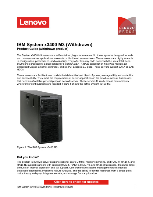
IBM System x3400 M3 (Withdrawn)Product Guide (withdrawn product)The System x3400 M3 servers are self-contained, high-performance, 5U tower systems designed for web and business server applications in remote or distributed environments. These servers are highly scalable in configuration, performance, and availability. They offer two-way SMP power with the latest Intel Xeon 5600 series processors, a dual connector 8-port SAS/SATA RAID controller on hot-swap models, an embedded Gigabit Ethernet controller, and six PCI Express 2.0 slots. These servers support SATA or SAS HDDs.These servers are flexible tower models that deliver the best blend of power, manageability, expandability, and serviceability. They meet the requirements of server applications in the small-to-medium businesses that need an affordable general-purpose network server. These servers fit into business environments where tower configurations are required. Figure 1 shows the IBM® System x3400 M3.Figure 1. The IBM System x3400 M3Did you know?The System x3400 M3 server supports optional spare DIMMs, memory mirroring, and RAID-0, RAID-1, and RAID-1E support standard with optional RAID-5, RAID-6, RAID-10, and RAID-50 available. It features large amounts of internal expansion and I/O support. Comprehensive systems management tools such as advanced diagnostics, Predictive Failure Analysis, and the ability to control resources from a single point make it easy to deploy, integrate, service, and manage from any location.Click here to check for updatesFigure 2. Front view of the IBM System x3400 M3Figure 3. Rear view of the IBM System x3400 M3Figure 4 shows the locations of key components inside the server.Figure 4. Inside view of the IBM System x3400 M3 Standard specificationsThe following table lists the standard specifications. Table 1. Standard specificationsStandard modelsThe following table lists the standard models. Table 2. Standard modelsModel†Intel Processor*(2 maximum)RAM DiskcontrollerDisk bays(std/max)Disks Network Optical PowersupplyModels announced February 20117378/ 7379-A2x 1x E5603 4C 1.60GHz4 MB 1066 MHz1x 2GBIntegratedSATA(no RAID)4x 3.5"SS / 4Open 2 x GbE DVD1x 670 WFixed7378/ 7379-A4x 1x E5603 4C 1.60GHz4 MB 1066 MHz1x 2GBServeRAIDBR10il v24x 3.5"HS / 4Open 2 x GbE DVD1x 670 WFixed7378/ 7379-B2x 1x E5606 4C 2.13GHz8 MB 1066 MHz1x 2GBIntegratedSATA(no RAID)4x 3.5"SS / 4Open 2 x GbE DVD1x 670 WFixed7378/ 7379-B4x 1x E5606 4C 2.13GHz8 MB 1066 MHz1x 2GBServeRAIDBR10il v24x 3.5"HS / 4Open 2 x GbE DVD1x 670 WFixed7378/ 7379-C2x 1x E5607 4C 2.26GHz8 MB 1066 MHz1x 2GBServeRAIDBR10il v24x 3.5"HS / 4Open 2 x GbE DVD1x 670 WFixed7378/ 7379-56x 1x E5620 4C 2.40GHz12 MB 1066 MHz1x 4GBServeRAIDBR10il v24x 3.5"HS / 4Open 2 x GbE DVD1x 670 WFixed7378/ 7379-58x 1x E5620 4C 2.40GHz12 MB 1066 MHz1x 4GBServeRAIDM10158x 2.5"HS / 16Open 2 x GbE DVD 1 x 920 WHot-swap7378/ 7379-D2x 1x E5645 6C 2.40GHz12 MB 1333 MHz1x 4GBServeRAIDM10158x 2.5"HS / 8Open 2 x GbE DVD1x 670 WFixed7378/ 7379-F2x 1x E5649 6C 2.53GHz12 MB 1333 MHz1x 4GBServeRAIDM501416x 2.5"HS / 16Open 2 x GbE DVD 1 x 920 WHot-swap† The x3400 M3 is available as machine type 7378 with a 1-year warranty (AP only) or as machine type 7379 with a 3-year warranty. This is the only difference between systems of the same model (for example, comparing 7378-A2x and 7379-A2x).* In the processor column: Standard quantity of processors, processor model, core speed, cores, L3 cache, memory speed.Refer to the Standard Specifications section for information about standard features of the server.Express modelsThe following table lists the region-specific Express models. Express models are preconfigured with additional components, such as processors and memory, to make the ordering and installation process simpler.Table 3. Express modelsRegion/ model Processor* (2maximum)Memory RAIDcontrollerDiskbays(std /max)Disks Network Optical PowersupplyNA and LA7379-E1U 1x Xeon E5503 2.0GHz 2C 4 MB 800MHz3x 2 GB BR10il v24x 3.5"SS / 4Optional2x GbE DVD-ROM1x 670W7379-E2U 1x Xeon E5506 2.13GHz 4C 4 MB 800MHz3x 4 GB BR10il v24x 3.5"HS / 4Optional2x GbE DVD-ROM1x 670W7379-E3U 1x Xeon E5620 2.40GHz 4C 12 MB 1066MHz3x 4 GB M10158x 2.5"HS / 16Optional2x GbE DVD-ROM1x 920WNE and SW IOT7379-K1G 1x Xeon E5503 2.0GHz 2C 4 MB 800MHz1x 2 GB BR10il v24x 3.5"SS / 4Optional2x GbE DVD-ROM1x 920W7379-K2G 1x Xeon E5506 2.13GHz 4C 4 MB 800MHz1x 4 GB M10154x 3.5"HS / 8Optional2x GbE Multiburner1x 920W7379-K3G 1x Xeon E5507 2.26GHz 4C 4 MB 800MHz1x 4 GB M1015 +AdvanceFeatureKey8x 2.5"HS / 16Optional2x GbE Multiburner1x 920W7379-K4G 1x Xeon E5620 2.40GHz 4C 12 MB 1066MHz1x 4 GB M1015 +AdvanceFeatureKey8x 2.5"HS / 16Optional2x GbE Multiburner2x 920W7379-K8G 1x Xeon E5506 2.13GHz 4C 4 MB 800MHz1x 4 GB M50144x 3.5"HS / 8Optional2x GbE Multiburner2x 920W7379-KDG 1x Xeon E5620 2.40GHz 4C 12 MB 1066MHz1x 4 GB M50148x 2.5"HS / 162x 146 GB2x GbE Multiburner1x 920W7379KXG1x Xeon E5607 2.26GHz 4C 8 MB 1333MHz 1x 4 GB M10158x 2.5"HS / 8Optional2x GbE Multiburner1x 670W7379KZG1x Xeon E5620 2.4GHz 4C 12 MB 1333MHz 1x 2 GB M50146x 2.5"HS / 8Optional2x GbE Multiburner1x 670WCEE and MEA IOT7379-K5G 1x Xeon E5506 2.13GHz 4C 4 MB 800MHz2x 4 GB M10154x 3.5"HS / 8Optional2x GbE Multiburner1x 920W7379-K6G 1x Xeon E5506 2.13GHz 4C 4 MB 800MHz1x 4 GB M50148x 2.5"HS / 162x 146 GB2x GbE Multiburner2x 920W7379-K8G 1x Xeon E5506 2.13GHz 4C 4 MB 800MHz1x 4 GB M50144x 3.5"HS / 8Optional2x GbE Multiburner2x 920W7379-KDG 1x Xeon E5620 2.40GHz 4C 12 MB 1066MHz1x 4 GB M50148x 2.5"HS / 162x 146 GB2x GbE Multiburner1x 920W7379-KBG 1x Xeon E5620 2.40GHz 4C 12 MB 1066MHz1x 4 GB M50144x 3.5"HS / 8Optional2x GbE Multiburner1x 920WRCIS7379-K9G 1x Xeon E5506 2.13GHz 4C 4 MB 800MHz1x 4 GB M50144x 3.5"HS / 8Optional2x GbE Multiburner1x 920W7379-KAG 1x Xeon E5506 2.13GHz 4C 4 MB 800MHz1x 4 GB M5014 +Battery4x 3.5"HS / 8Optional2x GbE Multiburner1x 920W7379-KBG 1x Xeon E5620 2.40GHz 4C 12 MB 1066MHz1x 4 GB M50144x 3.5"HS / 8Optional2x GbE Multiburner1x 920W7379-KCG 1x Xeon E5620 2.40GHz 4C 12 MB 1066MHz2x 4 GB M5015 +Battery8x 2.5"HS / 16Optional2x GbE Multiburner1x 920WJapan7379-PAM 1x Xeon E5503 2.0GHz 2C 4 MB 800MHz2x 2 GB BR10il v24x 3.5"HS / 82x 1 TB2x GbE DVD-ROM1x 920W7379-PAN 1x Xeon E5506 2.13GHz 4C 4 MB 800MHz2x 2 GB M5014 +Battery4x 3.5"HS / 83x 300 GB2x GbE DVD-ROM1x 920WChina7379-I011x Xeon E5506 2.13GHz 4C 4 MB 800MHz 1x 4 GB M10158x 2.5"HS / 81x 146 GB2x GbE DVD-ROM1x 670W7379-I051x Xeon E5506 2.13GHz 4C 4 MB 800MHz 1x 4 GB M5015 (nobattery)8x 2.5"HS / 81x 146 GB2x GbE DVD-ROM1x 670W7379-I211x Xeon E5620 2.40GHz 4C 12 MB 1066MHz 1x 4 GB M10158x 2.5"HS / 81x 146 GB2x GbE DVD-ROM1x 670W7379-I251x Xeon E5620 2.40GHz 4C 12 MB 1066MHz 1x 4 GB M5015 (nobattery)8x 2.5"HS / 81x 146 GB2x GbE DVD-ROM1x 670WISA7379-I4S1x Xeon E5506 2.13GHz 4C 4 MB 800MHz 1x 2 GB BR10i4x 3.5"SS / 41x 250 GB2x GbE DVD-ROM1x 670W7379-I3S1x Xeon E5507 2.26GHz 4C 4 MB 800MHz 1x 4 GB BR10i8x 2.5"HS / 161x 146 GB2x GbE DVD-ROM2x 920WHong Kong7379-I5H1x Xeon E5506 2.13GHz 4C 4 MB 800MHz 2x 2 GB M50144x 3.5"HS / 4Optional2x GbE DVD-ROM1x 670W* In the processor column: standard quantity of processors, processor model, core speed, cores, L3 cache, memory speed.Processor optionsThe server supports the processor options listed in the following table. The server supports up to two processors. The table also shows which server models have each processor standard. If there is no corresponding where-used model for a particular processor, then this processor is only available through CTO.Table 4. Processor optionsFeature code**Description Standard modelswhere usedIntel Xeon 5600 series processorsA0VC / A0VD Intel Xeon Processor E5603 4C 1.60GHz 4 MB Cache 1066MHz 80w A2x, A4xA0VE / A0VF Intel Xeon Processor E5606 4C 2.13GHz 8 MB Cache 1066MHz 80w B2x, B4xA0VG / A0VH Intel Xeon Processor E5607 4C 2.26GHz 8 MB Cache 1066MHz 80w C2x4493 / 4631Intel Xeon Processor E5620 4C 2.40GHz 12 MB Cache 1066MHz 80w52x, 54x, 56x, 58x 4494 / 4632Intel Xeon Processor E5630 4C 2.53GHz 12 MB Cache 1066MHz 80w62x4495 / 4633Intel Xeon Processor E5640 4C 2.66GHz 12 MB Cache 1066MHz 80w72x, 74xA0VJ / A0VK Intel Xeon Processor E5645 6C 2.40GHz 12 MB Cache 1333MHz 80w D2xA0VL / A0VM Intel Xeon Processor E5649 6C 2.53GHz 12 MB Cache 1333MHz 80w F2x0723 / 7683Intel Xeon Processor L5609 4C 1.86GHz 12 MB Cache 1066MHz 40w-0722 / 7682Intel Xeon Processor L5630 4C 2.13GHz 12 MB Cache 1066MHz 40w-0721 / 7681Intel Xeon Processor L5640 6C 2.26GHz 12 MB Cache 1333MHz 60w-4496 / 4634Intel Xeon Processor X5650 6C 2.66GHz 12 MB Cache 1333MHz 95w-4497 / 4635Intel Xeon Processor X5660 6C 2.80GHz 12 MB Cache 1333MHz 95w-4498 / 4636Intel Xeon Processor X5670 6C 2.93GHz 12 MB Cache 1333MHz 95w-A0VS / A0VT Intel Xeon Processor X5675 6C 3.06GHz 12 MB Cache 1333MHz 95w-Intel Xeon 5500 series processors0705 / 4639*Intel Xeon Processor E5503 2C 2.0 GHz 4 MB Cache 800 MHz 80w22x, 24x6656 / 6955Intel Xeon Processor E5504 4C 2.00 GHz 4 MB Cache 800MHz 80w-4428 / 4427Intel Xeon Processor E5506 4C 2.13 GHz 4 MB Cache 800MHz 80w32x, 34x0706 / 4640*Intel Xeon Processor E5507 4C 2.26 GHz 4 MB Cache 800MHz 80w42x4425 / 4424Intel Xeon Processor E5540 4C 2.53 GHz 8 MB Cache 1066MHz 80w-** The first feature code is for Processor 1. The second feature code is for Processor 2.* Withdrawn from marketing.Memory optionsFigure 5. Internal drive configurationsPart number FeaturecodeDescription Maximumsupported*3.5" Simple-Swap SATA and NL SATA HDDs81Y9778A280IBM 3TB 7.2K 6Gbps NL SATA 3.5" SS HDD4 42D07875416IBM 2 TB 7200 NL SATA 3.5" SS HDD4 39M45145288500 GB 7200 RPM 3.5" Simple-Swap SATA II4 3.5" Hot-Swap SATA and NL SATA HDD81Y9774A27Z IBM 3 TB 7.2K 6Gbps NL SATA 3.5" HS HDD8 42D07825415IBM 2 TB 7200 NL SATA 3.5" HS HDD8 43W76265560IBM 1 TB 7200 SATA 3.5" HS HDD8 39M45305196500 GB 7200 RPM 3.5" Hot-Swap SATA II83.5" Hot-Swap SAS HDDs44W22445313IBM 600 GB 15 K 6 Gbps SAS 3.5" Hot-Swap HDD844W22395312IBM 450 GB 15 K 6 Gbps SAS 3.5" Hot-Swap HDD844W22345311IBM 300 GB 15 K 6 Gbps SAS 3.5" Hot-Swap HDD83.5" Hot-Swap NL SAS HDDs81Y9758A281IBM 3 TB 7.2K 6Gbps NL SAS 3.5" HS HDD842D07675417IBM 2 TB 7.2 K 6 Gbps NL SAS 3.5" HS HDD842D07775418IBM 1 TB 7.2 K 6 Gbps NL SAS 3.5" HS HDD82.5" Hot-swap SAS-SSD Hybrid Drive00AD102A4G7IBM 600GB 10K 6Gbps SAS 2.5'' G2HS Hybrid162.5" Hot-Swap NL SATA HDDs81Y9730A1AV IBM 1TB 7.2K 6Gbps NL SATA 2.5" SFF HS HDD1681Y9726A1NZ IBM 500GB 7.2K 6Gbps NL SATA 2.5" SFF HS HDD1681Y9722A1NX IBM 250GB 7.2K 6Gbps NL SATA 2.5" SFF HS HDD162.5" Hot-Swap 10K SAS HDDs00AD075A48S IBM 1.2TB 10K 6Gbps SAS 2.5'' G2HS HDD1681Y9650A282IBM 900GB 10K 6Gbps SAS 2.5" Slim-HS HDD1649Y20035433IBM 600 GB 10 K 6 Gbps SAS 2.5" SFF Slim-HS HDD1642D06375599IBM 300 GB 10 K 6 Gbps SAS 2.5" SFF Slim-HS HDD162.5" Hot-Swap 15K SAS HDDs81Y9670A283IBM 300GB 15K 6Gbps SAS 2.5" SFF HS HDD1642D06775536IBM 146 GB 15 K 6 Gbps SAS 2.5" SFF Slim-HS HDD162.5" Hot-Swap NL SAS HDDs81Y9690A1P3IBM 1TB 7.2K 6Gbps NL SAS 2.5" SFF HS HDD1642D07075409IBM 500 GB 7200 6 Gbps NL SAS 2.5" SFF Slim-HS HDD162.5" Solid state drives00W1125A3HR IBM 100GB SATA 2.5" MLC HS Enterprise SSD1643W7718A2FN IBM 200GB SATA 2.5" MLC HS SSD1649Y5839A3AS IBM 64GB SATA 2.5" MLC HS Enterprise Value SSD1649Y5844A3AU IBM 512GB SATA 2.5" MLC HS Enterprise Value SSD1690Y8643A2U3IBM 256GB SATA 2.5" MLC HS Enterprise Value SSD1690Y8648A2U4IBM 128GB SATA 2.5" MLC HS Enterprise Value SSD16* If the server has a 670 W fixed power supply, then only 4x 3.5-inch drives or 8x 2.5-inch drives can be installed.Internal backup unitsStorage host bus adaptersThe following table lists storage HBAs supported by the x3400 M3 server. Table 12. Storage adaptersPart number FeaturecodeDescription Maximumquantity supportedFibre Channel59Y19873885Brocade 4 Gb FC Single-port HBA for IBM System x359Y19933886Brocade 4 Gb FC Dual-port HBA for IBM System x346M60493589Brocade 8 Gb FC Single-port HBA for IBM System x346M60503591Brocade 8 Gb FC Dual-port HBA for IBM System x381Y1668A2XU Brocade 16Gb FC Single-port HBA for IBM System x381Y1675A2XV Brocade 16Gb FC Dual-port HBA for IBM System x342C20691698Emulex 4 Gbps FC Single-Port PCI-e HBA for IBM System x642C20711699Emulex 4 Gbps FC Dual-Port PCI-e HBA for IBM System x642D04853580Emulex 8 Gb FC Single-port HBA for IBM System x642D04943581Emulex 8 Gb FC Dual-port HBA for IBM System x681Y1655A2W5Emulex 16Gb FC Single-port HBA for IBM System x381Y1662A2W6Emulex 16Gb FC Dual-port HBA for IBM System x339R65253567QLogic 4 Gb FC Single-Port PCIe HBA for IBM System x639R65273568QLogic 4 Gb FC Dual-Port PCIe HBA for IBM System x642D05013578QLogic 8 Gb FC Single-port HBA for IBM System x642D05103579QLogic 8 Gb FC Dual-port HBA for IBM System x600Y3337A3KW QLogic 16Gb FC Single-port HBA for IBM System x300Y3341A3KX QLogic 16Gb FC Dual-port HBA for IBM System x3Converged Network Adapters (CNA)*42C18005751QLogic 10 Gb Dual Port CNA for IBM System x342C18201637Brocade 10 Gb Dual-port CNA for IBM System x3iSCSI39Y61462976QLogic iSCSI Single-Port PCIe HBA for IBM System x642C17702977QLogic iSCSI Dual-Port PCIe HBA for IBM System x6SAS44E87003583IBM 3 Gb SAS HBA v2346M09075982IBM 6 Gb SAS HBA Controller346M09123876IBM 6Gb Performance Optimized HBA1* Converged Network Adapters require SFP+ optical transceivers or DAC cables that must be purchased separately.For more information, see the list of IBM Redbooks Product Guides in the Host bus adapters category: /portals/systemx?Open&page=pg&cat=hbaPCIe SSD adaptersPCIe SSD adaptersThe server does not support High IOPS SSD adapters.Power suppliesThe server supports either one 670 W AC fixed power supply or up to two 920 W AC hot-swap redundant power supplies, providing N+N redundancy. Standard models come with one power supply, either fixed or hot-swap, depending on the model as listed in Table 2. For models with one 920 W AC hot-swap redundant power supply, you can add a second power supply by ordering the option listed in the following table.Note: If the server has a 670 W fixed power supply installed, then only up to four 3.5-inch drives can be installed or up to eight 2.5-inch drives can be installed.Table 13. Power suppliesPart number Feature code Description Maximum supported44X03815056IBM Redundant Power Supply for x3400/3500 2 (One power supply comesstandard with every model.)The power supply ships without a line cord. A line cord must be ordered separately.Note: Power supply option 44X0381 is for both the x3400 M3 and the x3500 M3. The power supply option includes three fans however these fans are only for use with the x3500 M3. They are not used in the x3400 M3. (The x3400 M3 includes physical space for the fans but there is no electrical connection for the fans in the x3400 M3.)Integrated virtualizationThe server supports VMware ESXi installed on a USB memory key. The key is installed in a USB socket inside the server. The following table lists the virtualization options.Table 14. Virtualization optionsPart number FeaturecodeDescription Maximumsupported41Y82781776IBM USB Memory Key for VMware ESXi 41 41Y82873033IBM USB Memory Key for VMware ESXi 4.11 41Y8296A1NP IBM USB Memory Key for VMware ESXi 4.1 Update 11 41Y8300A2VC IBM USB Memory Key for VMware ESXi 5.01 41Y8307A383IBM USB Memory Key for VMware ESXi 5.0 Update 11 41Y8311A2R3IBM USB Memory Key for VMware ESXi 5.11Remote managementExternal backup unitsThe server supports the external backup attachment options listed in the following table. Table 22. External backup optionsPart number DescriptionExternal tape expansion enclosures for internal tape drives87651UX1U Tape Drive Enclosure8767HHX Half High Tape Drive Enclosure87651NX1U Tape Drive Enclosure (with Nema 5-15P LineCord)8767HNX Half High Tape Drive Enclosure (with Nema 5-15P LineCord)Tape enclosure adapters (with cables)44E8869USB Enclosure Adapter Kit40K2599SAS Enclosure Adapter KitInternal backup drives supported by external tape enclosures46C5364IBM RDX Removable Hard Disk Storage System - Internal USB 160 GB Bundle 46C5387IBM RDX Removable Hard Disk Storage System - Internal USB 320 GB Bundle 46C5388IBM RDX Removable Hard Disk Storage System - Internal USB 500 GB Bundle 46C5399IBM DDS Generation 5 USB Tape Drive39M5636IBM DDS Generation 6 USB Tape Drive43W8478IBM Half High LTO Gen 3 SAS Tape Drive44E8895IBM Half High LTO Gen 4 SAS Tape Drive49Y9898IBM Half High LTO Gen 5 Internal SAS Tape DriveExternal backup units*362516X IBM RDX Removable Hard Disk Storage System - External USB 160 GB Bundle362532X IBM RDX Removable Hard Disk Storage System - External USB 320 GB Bundle362550X IBM RDX Removable Hard Disk Storage System - External USB 500 GB Bundle3628L3X IBM Half High LTO Gen 3 External SAS Tape Drive (with US line cord)3628L4X IBM Half High LTO Gen 4 External SAS Tape Drive (with US line cord)3628L5X IBM Half High LTO Gen 5 External SAS Tape Drive (with US line cord)3628N3X IBM Half High LTO Gen 3 External SAS Tape Drive (without line cord)3628N4X IBM Half High LTO Gen 4 External SAS Tape Drive (without line cord)3628N5X IBM Half High LTO Gen 5 External SAS Tape Drive (without line cord)3580S3V System Storage TS2230 Tape Drive Express Model H3V3580S4V System Storage TS2240 Tape Drive Express Model H4V3580S5E System Storage TS2250 Tape Drive Express Model H5S3580S5X System Storage TS2350 Tape Drive Express Model S533572S4R TS2900 Tape Library with LTO4 HH SAS drive & rack mount kit3572S5R TS2900 Tape Library with LTO5 HH SAS drive & rack mount kit35732UL TS3100 Tape Library Model L2U Driveless35734UL TS3200 Tape Library Model L4U Driveless46X2682†LTO Ultrium 5 Fibre Channel Drive46X2683†LTO Ultrium 5 SAS Drive Sled46X2684†LTO Ultrium 5 Half High Fibre Drive Sled46X2685†LTO Ultrium 5 Half High SAS Drive Sled46X6912†LTO Ultrium 4 Half High Fibre Channel Drive Sled46X7117†LTO Ultrium 4 Half High SAS DriveV2 Sled46X7122†LTO Ultrium 3 Half High SAS DriveV2 Sled* Note: The external tape drives listed can be ordered through System x sales channel. Server may support other IBM tape drives that are not listed in this table. Refer to IBM System Storage Interoperability Center for further information.† Note: These part numbers are the tape drives options for 35732UL and 35734UL.For more information, see the list of IBM Redbooks Product Guides in the Backup units category:/portals/systemx?Open&page=pg&cat=tapeTop-of-rack Ethernet switchesThe server supports the following top-of-rack Ethernet switches from IBM System Networking.Table 23. IBM System Networking - Top-of-rack switchesPart number DescriptionIBM System Networking - 1 Gb top-of-rack switches0446013IBM System Networking RackSwitch G8000R7309CFC IBM System Networking RackSwitch G8000F7309CD8IBM System Networking RackSwitch G8000DC7309G52IBM System Networking RackSwitch G8052R730952F IBM System Networking RackSwitch G8052F427348E IBM Ethernet Switch J48E6630010Juniper Networks EX2200 24 Port6630011Juniper Networks EX2200 24 Port with PoE6630012Juniper Networks EX2200 48 Port6630013Juniper Networks EX2200 48 Port with PoEIBM System Networking - 10 Gb top-of-rack switches7309DRX IBM System Networking RackSwitch G8264CS (Rear to Front)7309DFX IBM System Networking RackSwitch G8264CS (Front to Rear)7309BD5IBM System Networking RackSwitch G8124DC7309BR6IBM System Networking RackSwitch G8124ER7309BF7IBM System Networking RackSwitch G8124EF7309G64IBM System Networking RackSwitch G8264R730964F IBM System Networking RackSwitch G8264F7309CR9IBM System Networking RackSwitch G8264TR7309CF9IBM System Networking RackSwitch G8264TF0719410Juniper Networks EX4500 - Front to Back Airflow0719420Juniper Networks EX4500 - Back to Front AirflowIBM System Networking - 40 Gb top-of-rack switches8036ARX IBM System Networking RackSwitch G8316R8036AFX IBM System Networking RackSwitch G8316FFor more information, see the list of IBM Redbooks Product Guides in the Top-of-rack switches category: /portals/systemx?Open&page=pg&cat=torPart number DescriptionSwitched and Monitored PDUs46M4002IBM 1U 9 C19/3 C13 Active Energy Manager DPI® PDU46M4003IBM 1U 9 C19/3 C13 Active Energy Manager 60A 3 Phase PDU46M4004IBM 1U 12 C13 Active Energy Manager DPI PDU46M4005IBM 1U 12 C13 Active Energy Manager 60A 3 Phase PDU46M4167IBM 1U 9 C19/3 C13 Switched and Monitored 30A 3 Phase PDU46M4116IBM 0U 24 C13 Switched and Monitored 30A PDU46M4119IBM 0U 24 C13 Switched and Monitored 32A PDU46M4134IBM 0U 12 C19/12 C13 Switched and Monitored 50A 3 Phase PDU46M4137IBM 0U 12 C19/12 C13 Switched and Monitored 32A 3 Phase PDUEnterprise PDUs71762MX IBM Ultra Density Enterprise PDU C19 PDU+ (WW)71762NX IBM Ultra Density Enterprise PDU C19 PDU (WW)71763MU IBM Ultra Density Enterprise PDU C19 3 phase 60A PDU+ (NA)71763NU IBM Ultra Density Enterprise PDU C19 3 phase 60A PDU (NA)39M2816IBM DPI C13 Enterprise PDU without linecord39Y8923DPI 60A Three Phase C19 Enterprise PDU with IEC309 3P+G (208 V) fixed line cord 39Y8941DPI Single Phase C13 Enterprise PDU without line cord39Y8948DPI Single Phase C19 Enterprise PDU without line cordFront-End PDUs39Y8934DPI 32amp/250V Front-end PDU with IEC 309 2P+Gnd connector39Y8935DPI 63amp/250V Front-end PDU with IEC 309 2P+Gnd connector39Y893830amp/125V Front-end PDU with NEMA L5-30P connector39Y893930amp/250V Front-end PDU with NEMA L6-30P connector39Y894060amp/250V Front-end PDU with IEC 309 60A 2P+N+Gnd connectorUniversal PDUs39Y8951DPI Universal Rack PDU w/ US LV and HV line cords 39Y8952DPI Universal Rack PDU w/ CEE7-VII Europe LC39Y8953DPI Universal Rack PDU w/ Denmark LC39Y8954DPI Universal Rack PDU w/ Israel LC39Y8955DPI Universal Rack PDU w/Italy LC39Y8956DPI Universal Rack PDU w/South Africa LC39Y8957DPI Universal Rack PDU w/UK LC39Y8958DPI Universal Rack PDU with AS/NZ LC39Y8959DPI Universal Rack PDU w/China LC39Y8962DPI Universal Rack PDU (Argentina)39Y8960DPI Universal Rack PDU (Brazil)39Y8961DPI Universal Rack PDU (India)0U Basic PDUs46M4122IBM 0U 24 C13 16A 3 Phase PDU46M4125IBM 0U 24 C13 30A 3 Phase PDU46M4128IBM 0U 24 C13 30A PDU46M4131IBM 0U 24 C13 32A PDU46M4140IBM 0U 12 C19/12 C13 60A 3 Phase PDU46M4143IBM 0U 12 C19/12 C13 32A 3 Phase PDURack cabinetsThe server supports the rack cabinets listed in the following table. Tower-to-Rack Conversion Kit (part number 69Y0893, 5Ux26" Tower to Rack Conversion Kit for x3400/x3500) is required for the server to be installed in a rack.Table 26. Rack cabinetsPart number Description69Y08935Ux26" Tower to Rack Conversion Kit for x3400/x3500201886X IBM 11U Office Enablement Kit14102RX IBM eServer Cluster 25U Rack93072PX IBM 25U Static S2 Standard Rack93072RX IBM 25U Standard Rack93074RX IBM 42U Standard Rack93074XX IBM 42U Standard Rack Extension14104RX IBM 42U S2 standard rack93084EX IBM 42U Enterprise Expansion Rack93084PX IBM 42U Enterprise Rack93604EX IBM 42U 1200 mm Deep Dynamic Expansion Rack93604PX IBM 42U 1200 mm Deep Dynamic Rack93614EX IBM 42U 1200 mm Deep Static Expansion Rack93614PX IBM 42U 1200 mm Deep Static Rack93624EX IBM 47U 1200 mm Deep Static Expansion Rack93624PX IBM 47U 1200 mm Deep Static RackFor more information, see the IBM 47U and 42U 1200mm Deep Racks at-a-glance guide, available from: /abstracts/tips0796.html?OpenTrademarksLenovo and the Lenovo logo are trademarks or registered trademarks of Lenovo in the United States, other countries, or both. A current list of Lenovo trademarks is available on the Web athttps:///us/en/legal/copytrade/.The following terms are trademarks of Lenovo in the United States, other countries, or both:Lenovo®BladeCenter®RackSwitchServeRAIDServerGuideServerProven®System x®The following terms are trademarks of other companies:Intel® and Xeon® are trademarks of Intel Corporation or its subsidiaries.Linux® is the trademark of Linus Torvalds in the U.S. and other countries.Microsoft®, Windows Server®, and Windows® are trademarks of Microsoft Corporation in the United States, other countries, or both.Other company, product, or service names may be trademarks or service marks of others.。
Origo Mig 4004i 5004i 和 Origo Feed 3004 4804 产品说明书

Origo™ Mig 4004i/5004iOrigo™ Feed 3004/4804, MA23/MA24Origo™ Mig 4004i, A44Lightweight multi process inverter equipment• High Duty Cycle –suitable for long runs•Wide mains input tolerance: 380 -440 V +/-10%•Generator compatible –for on site use •Standby Function –energy saving system • 35 Synergic lines –preset welding parameters (MA24)• QSet™ –Intelligent welding system (MA24)•Creep-start™ for a more controlled start (MA24)• Integrated cooling with ELP (ESAB Logic Pump), on demand system• Sturdy trolley with 4 lifting eyes –fully transportableThe Origo™ Mig 4004i/5004i are electronic controlled MIG/MAG/MMA lightweight inverter based welding equipment, designed for high productivity welding applications.XA00157820When compared to a conventional equipment the floor space is reduced by 70% with the minimal footprint of the new Origo™ power sources. This new compact design has also seen a 80% decrease in weight making them truly transportable.On demand cooling systems increase the welding time of the equipment and keeps the torch cooler to givegreater comfort to the welder. The cooling fan and water cooling system automatically turn off after 6.5 minutes inactivity, significantly reducing the idle time energy consumption.This 4th generation inverter offers considerableimproved efficiency and power factor is approximately 1. This gives you minimized energy consumption and will offer significant reductions in your energy cost with the same welding conditions.Technology Weight Efficiency Step controlled >140 kg <70%Chopper >140 kg <70%Inverter (Origo™ Mig)<50 kg>85%•Highly productive MIG/MAG welding •Advanced MMA welding without feeder•Typical market segments:-General Industrial Fabrication -Energy Generation -Windmills-Trucks Busses and Trailers -Trains & Railway Cars-Earthmoving and Mining Equipment -Mobile Machinery -Steel Sections-Shipbuilding/OffshoreApplicationsQSet™ -The intelligence welding system which simplifies weldingQSet™ monitors the welding arc and optimizes welding parameters in dip transfer, just weld and the arc condition will be optimized within a few seconds. Then simply adjust the wire feed speed to suit the application and let QSet™ do the rest.A robust fully enclosed design protects the welding wire from moisture, dust and other airborne contaminants. The Origo™ Feed 3004/4804 is available with a choice of two control panels which both have a simple, logical layout to make it easy to operate and are easilyinterchangeable. A remote control socket allows a remote control to be used or with an RA23 adaptor a PSF RS3 welding torch can be used to allow welding schedules to be changed at the torch.Either standard spools or MarathonPac™ wire can be used and cable wear is minimized with strain relief fitted to the rear of the feeder.Origo™ Feed 3004Weldingmethod MIG/MAG MMASelection ofMIG/MAG welding, Synergic mode*, QSet™*, ManualCreep-start™*Crater Fill*2 stroke 4 strokePanel mode Local OperationMemoryVoltage Reduction DeviceGas purgeInchingMemory selectionStepless InductanceAdjustable Crater fill time*35 Synergic lines*Customizing on demandVoltage adjustment QSet™ adaption*Power adjustment (in synergic mode*)Wire Feed Speed (In manual and QSet™ mode*)Display mode indicatorsSynergic linesSynergic lines is a tool to quickly find an acceptable arc length. From this point, you will have a goodopportunity to fine tune for best results in your typical welding cases.A synergy line also helps the operator to more and quickly, avoid the global regions between short arc and spray arc. The synergic line also chooses the best Arc control type* for the given gas and wire combination. *=dynamic regulationMA23/MA24(* Extra functions for MA24)Origo™ Feed 4804Technical data Origo™ MigLiveTig™A44 gives you LiveTig™ start that electronically controls the start current. You can weld mild steel or stainless steel with or without filler material. The startingprocedure can be compared to Lift Arc ™, meaning you don’t need to scratch the work piece with the electrode. Air gougingBy choosing the MIG/MAG Arc Voltage Control setting you will achieve the best performance and avoiding arc out.Origo™ Mig 4004i, A44COOL 1Power supply, from power source, VDC 24Coolant flow capacity, l/min 2.0Coolant quantity, l 4.5Cooling power, kW 1.3Max pressure, bar4.5Max pressure height to torch, m 8.5Weight / incl. coolant, kg12 / 16.5Dimensions incl. filler tube lxwxh, mm610x256x256Technical data, Water cooler COOL 1Power supply, AC42Wire spool capacity, kg 18 / 18 (30**)Max. spool diameter, mm 300 / 300 (440**)Wire feed speed, m/min 0.8-25.0Dimension (l x w x h), mm 690x275x420Weight, kg15 / 19Wire dimensions:Steel0.6-1.6 / 0.6-2.4Stainless steel 0.6-1.6 / 0.6-2.4 Aluminium 1.0-1.6 / 1.0-2.4Cored wire0.8-1.6 / 0.8-2.4Technical data, Origo™ Feed 3004/4804Welding methodMMA, MIG/MAG=ArcVoltageControl -Air Gouging,LiveTig™Selection of dynamic control type (MMA)Voltage Reduction DeviceMemory selectionStepless InductanceArc ForceRemote ControlPower Adjustment Current/VoltageDisplay mode indicators Hot StartA444004i A444004i5004iMains SupplySingle Voltage 3 ph 50/60 Hz, V 380 –440380 –440380 –440±10% ±10% ±10%Mains cable, Ø mm 2 4 x 6 4 x 6 4 x 6Fuse, slow A,252535Permissible load at MIG/MAG 100% duty cycle A/V, 3ph 300/32 350/31,5 350/31,580% duty cycle A/V, 3ph -400/36400/3660% duty cycle A/V, 3ph 400/36-500/40Setting range A MIG/MAG 20 -40020 -40020 -500MMA 16 -40016 -40016 -500TIG4 -400 4 -400 4 -500Open circuit voltage, V555555Open circuit voltage VRD, V < 35< 35< 35Idle Power, W404040Efficiency at max. current %878989Power factor at max current 0.950.950.95Dimensions lxwxh mm610 x 256 x 445with cooling unit lxwxh, mm 610 x 256 x 675Weight, kg464646with cooling unit excl coolant, kg 585858Operating Temperature, °C -50-50-50Enclosure class IP23IP23IP23Application class S S S Insulation class H H H CertificationCECE CEThis welding equipment complies to IEC-EN974-1, IEC-EN974-2,IEC-EN974-5, IEC-EN974-102012-08-22 / E S A B r e s e r v e s t h e r i g h t t o a l t e r s p e c i f i c a t i o n s w i t h o u t p r i o r n o t i c eOrdering information, Origo™ FeedOrdering information, Interconnection cables70 mm 2Air-cooled Water-cooled 1.7 m, 10 pole 0459 528 7800459 528 7905.0 m, 10 pole 0459 528 7810459 528 79110.0 m, 10 pole 0459 528 7820459 528 79215.0 m, 10 pole 0459 528 7830459 528 79325.0 m, 10 pole 0459 528 7840459 528 79435.0 m, 10 pole 0459 528 7850459 528 79595 mm 2Air-cooled Water-cooled 1.7 m, 10 pole0459 528 9800459 528 990Ordering information, Power sourcesOrdering information, optionsProductP/NWheel kit for feeder0458 707 880Strain relief for welding torch0457 341 881Strain relief for interconnection cables 0459 234 880Lifting eye0458 706 880Quick connector MarathonPac™F102 440 880Adapter for 5 kg spool0455 410 001Spool cover0458 674 880Spool cover, steel0459 431 880Adapter for spool diameter 440 mm 0459 233 880**Remote control MTA1 CAN0459 491 880Remote control MT1 10Prog CAN 0459 491 882Remote interconn. Cable MTA1 and M1 10Prog, 5 m0459 960 880Remote adapter kit Miggy-/Railtrac 0459 681 880Remote adapter kit MXH™ PP and PSF™ RS30459 681 881MXH™ 300/400w PP connection kit 0459 020 883Water Cooler, COOL 10462 300 880Origo™ Mig 4004i/5004i 4-wheel trolley 0462 151 880Trolley bracket (without COOL 1)0463 125 880ProductP/NOrigo™ Mig 4004i, A440465 152 880Origo™ Mig 4004i 0465 154 880Origo™ Mig 5004i0465 155 880ProductAir-cooled Water-cooled Origo™ Feed 3004, MA23 Encl. 10 pole 0460 526 8870460 526 897 Origo™ Feed 4804, MA23 Encl. 10 pole 0460 526 997Origo™ Feed 3004, MA24 Encl. 10 pole 0460 526 8890460 526 899Origo™ Feed 4804, MA24 Encl. 10 pole0460 526 999ESAB AB Box 8004SE-402 77 GÖTEBORG SWEDENPhone: +46 31 50 90 00 Fax +46 31 22 04 49E-mail:************Synergic linesSyn. No.MaterialESAB designation Wire dim(mm)Shielding gas 1Fe ER70S-6OK AristoRod 12.50/12.510.8CO22Fe ER70S-6OK AristoRod 12.50/12.51 1.0CO23Fe ER70S-6OK AristoRod 12.50/12.51 1.2CO24Fe ER70S-6OK AristoRod 12.50/12.510.882%Ar+18%CO25Fe ER70S-6OK AristoRod 12.50/12.51 1.082%Ar+18%CO26Fe ER70S-6OK AristoRod 12.50/12.51 1.282%Ar+18%CO27Fe ER70S-6OK AristoRod 12.50/12.510.875%Ar+25%CO28Fe ER70S-6OK AristoRod 12.50/12.51 1.075%Ar+25%CO29Fe ER70S-6OK AristoRod 12.50/12.51 1.275%Ar+25%CO210Fe ER70S-6OK AristoRod 12.50/12.51*0.982-90% Ar 10-18% CO211ER 308LSI OK Autrod 308LSi 0.898% Ar 2%CO212ER 308LSI OK Autrod 308LSi 0.998% Ar 2%CO213ER 316LSI OK Autrod 316LSi 1.098%Ar+2%CO214ER 316LSI OK Autrod 316LSi 1.298%Ar+2%CO215ER 308LSI OK Autrod 308LSi*0.990% He 7.5% Ar 2.5% CO216ER 308LSI OK Autrod 308LSi* 1.290% He 7.5% Ar 2.5% CO217Al 5356OK Autrod 5356 1.0100%Ar 18Al 5356OK Autrod 5356 1.2100%Ar 19Al 5356OK Autrod 5356 1.6100%Ar 20Al 4043OK Autrod 4043 1.0100%Ar 21Al 4043OK Autrod 4043 1.2100%Ar 22Al 4043OK Autrod 4043 1.6100%Ar23Fe MCW E70C-6M OK Tubrod 14.12 1.282%Ar+18%CO224Fe MCW E70C-6M OK Tubrod 14.12 1.482%Ar+18%CO225Fe MCW E70C-6M OK Tubrod 14.12 1.682%Ar+18%CO226Fe MCW E70C-6M Coreweld C6* 1.292%Ar+8%CO227Fe MCW E70C-6M Coreweld C6* 1.692%Ar+8%CO228Fe RCW E71T-1M OK Tubrod 15.14 1.282%Ar+18%CO229Fe RCW E71T-1M OK Tubrod 15.14 1.482%Ar+18%CO230Fe RCW E71T-1M OK Tubrod 15.14 1.682%Ar+18%CO231Fe RCW E71T-1Dual Shield all-position* 1.275%Ar+25%CO232Fe RCW E71T-1Dual Shield all-position* 1.475%Ar+25%CO233Fe RCW E71T-1Dual Shield all-position* 1.675%Ar+25%CO234Fe BCW E71T-5OK Tubrod 15.00 1.282%Ar+18%CO235Fe RCW E71T-1Dual Shield 7100 LH* 1.2CO2*=US。
Shure MX405 MX410 MX415鹅颈话筒及配件用户指南

MX405 MX410 MX415 Gooseneck Microphones and AccessoriesThe Shure miniature gooseneck microphones, MX405, MX410 and MX415, user guide.Version: 5 (2019-J)Table of ContentsMX405 MX410 MX415Gooseneck Microphones and Accessories 3General Description3 Features 3 Model Variations 3 Snap-Fit Windscreen 8 Interchangeable Cartridges 9 MX400SMP Surface Mount Preamp9 Accessories 10 Installation11MX400SMP Pin Assignments 12 DIP Switches 12 LED Logic 13 MX400DP Desktop Base14 Installation 15 Cable 15 MX400DP DIP Switches 16 Local Mute Control 17 Logic Mute Control (Automatic Mixing) 18 Specifications19 Certifications25•••••MX405 MX410 MX415Gooseneck Microphones and Accessories General DescriptionShure MX405, MX410, and MX415 miniature gooseneck microphones are suitable for boardrooms and other sites where aesthetics are important. Permanently mount them at conference tables or lecterns using the MX400SMP surface mount, or use the MX400DP moveable desktop base, which includes a configurable mute button with logic output. Also compatible with the MX890 wireless desktop base and the ULXD8 wireless base.FeaturesLow profile, aesthetic designChoice of bi-color indicator or light ringWide dynamic range and smooth frequency responseRF filtering with CommShield technology Logic input for external LED controlModel VariationsThese gooseneck microphones are available in different lengths with a cardioid, supercardioid, or mini-shotgun cartridge and either a bi-color LED status indicator or a light ring. The 10 and 15 inch models are also available with a dualflex neck.®Gooseneck Microphones5" Cardioid Gooseneck Microphone MX405LP/C 5" Supercardioid Gooseneck Microphone MX405LP/S 5" Mini-shotgun Gooseneck Microphone MX405LP/MS 5" Gooseneck with Red Top LED (no cartridge)MX405RLP/N 10" Cardioid Gooseneck Microphone MX410LP/C 10" Supercardioid Gooseneck Microphone MX410LP/S 10" Gooseneck with Red Top LED (no cartridge)MX410RLP/N 10" Cardioid Dualflex Gooseneck Microphone MX410LPDF/C 10" Supercardioid Dualflex Gooseneck Microphone MX410LPDF/S 10" Dualflex Gooseneck with Red Top LED (no cartridge)MX410RLPDF/N 10" Cardioid Dualflex Gooseneck Microphone with Red Top LED MX410RLPDF/C 10" Supercardioid Dualflex Gooseneck Microphone with Red Top LED MX410RLPDF/S 15" Cardioid Gooseneck Microphone MX415LP/C 15" Supercardioid Gooseneck Microphone MX415LP/S•••15" Gooseneck with Red Top LED (no cartridge)MX415RLP/N 15" Cardioid Dualflex Gooseneck Microphone MX415LPDF/C 15" Supercardioid Dualflex Gooseneck Microphone MX415LPDF/S 15" Dualflex Gooseneck with Red Top LED (no cartridge)MX415RLPDF/N 15" Cardioid Dualflex Gooseneck Microphone with Red Top LED MX415RLPDF/C 15" Supercardioid Dualflex Gooseneck Microphone with Red Top LED MX415RLPDF/S 5" White Gooseneck Microphone (no cartridge)MX405WLP/N 5" White Gooseneck Microphone with Red Top LED (no cartridge)MX405WRLP/N 10" White Gooseneck Microphone (no cartridge)MX410WLP/N 10" White Gooseneck Microphone with Red Top LED (no cartridge)MX410WRLP/N 15" White Gooseneck Microphone (no cartridge)MX415WLP/N 15" White Gooseneck Microphone with Red Top LED (no cartridge)MX415WRLP/N 10" White Dualflex Gooseneck Microphone (no cartridge)MX410WLPDF/N 10" White Dualflex Gooseneck Microphone with Red Top LED (no cartridge)MX410WRLPDF/N 15" White Dualflex Gooseneck Microphone (no cartridge)MX415WLPDF/N 15" White Dualflex Gooseneck Microphone with Red Top LED (no cartridge)MX415WRLPDF/NCoverage and PlacementCardioid: One microphone for one or two people.Supercardioid: One microphone for each person.Mini-shotgun:One microphone for each person.CardioidSupercardioid•••Mini-shotgunMic PlacementSnap-Fit WindscreenSnap into the groove below the cartridge.To remove, spread the gap with a screwdriver or thumbnail.Provides 30 dB of "pop" protection.Interchangeable CartridgesMicroflex microphones use interchangeable cartridges that allow you to choose the polar pattern for different installations.Cartridge Polar PatternsMX400SMP Surface Mount PreampPermanent mount for conference tables or lecterns. Includes LED logic input.AccessoriesFurnished AccessoriesMX400SMP Surface Mount KitInstallationNote: Over tightening the wing nut reduces shock isolation.Caution: To prevent bending pins, line up key with notch and seat connector fully before twisting to lock.MX400SMP Pin Assignments5-Pin XLRDIP SwitchesSet DIP Switch 1 up to engage the low cut filter, which attenuates frequencies by 6 dB per octave below 150 Hz.Switch Down (default)Up1Full frequency response Low cut filter2LED steady LED flashesLED LogicTo operate the LED indicator, use the included 5-pin XLR connector to wire the microphone to an automatic mixer or other logic device.Note: Connect the LED IN to the gate output to illuminate the LED when the channel is gated on.Do not use the relay ports on Crestron and AMX devices. Use the I/O logic ports instead.The LED logic may not function when connecting to devices that do not have internal "pull-up resistor" logic circuits, such as ClearOne DSP products. External pullup resistor circuits can be added for each microphone. Visit /FAQ for detailed instructions.Logic ConnectionConnection to device with internal "pull-up resistor" logic circuitMX405, 410, 415Logic LOW (0 V)Logic HIGH (+5 V)MX405, 410, 415Green RedMX405R, 410R, 415RLogic LOW (0 V)Logic HIGH (+5V)Red Off/flashingMX400DP Desktop BaseThe MX400DP moveable desktop base includes a configurable mute button with logic output.MX400DP Desktop BaseInstallationCaution: To prevent bending pins, line up key with notch and seat connector fully before twisting to lock.CableThe 20 ft. attached cable is terminated with a 3-pin XLR connector. For logic applications, open the XLR connector to access the three unterminated logic conductors.Wire Color FunctionRed Audio +Black Audio −White SWITCH OUTOrange LED INGreen Logic GroundShield Mic Common GroundMX400DP Pin Assignments3-Pin XLRMX400DP DIP SwitchesCaution: Failure to reinstall the setscrew will reduce RF immunity.Switch Down (default)Up1Momentary Toggle2Push-to-Mute Push-to-Talk 3Local Mute Logic ControlSwitch Down (default)Up4Full Frequency Range Low Cut Filter (attenuates 6 dB per octave below 150 Hz)5LED Steady LED FlashesLocal Mute ControlThe microphone ships configured for local (manual) mute control (DIP Switch 3 down). In this mode, the PUSH button on the microphone mutes the audio signal at the microphone. Audio is not sent to the audio outputs when muted.In this configuration, the LED color reflects the microphone state, as controlled by the user with the PUSHbutton.Microphone StatusMX405, 410, 415MX405R, 410R, 415RActive Green RedMuted Red Off/flashingButton ConfigurationFor local mute control operation, use DIP Switches 1 and 2 to configure the button behavior.Button Behavior SWITCH OUT Logic Signal DIP Switch Setting Momentary: push-to-mute (as shipped).When pushed, SWITCH OUT (red wire) fallsto 0 V. When released, SWITCH OUT returns to +5 V.Momentary: push-to-talkButton Behavior SWITCH OUT Logic Signal DIP Switch SettingToggle: Push and release to toggle the microphone on or off. Mic is active whenpowered on.Push and release sets SWITCH OUT to 0 V.Push again to toggle back to +5 V.Toggle: Push and release to toggle the microphone on or off. Mic is mute whenpowered onLogic Mute Control (Automatic Mixing)Set DIP Switch 3 up to configure the microphone for logic control applications where audio from the microphone is muted by an external device, such as an automatic mixer. In this mode, the local mute function of the PUSH button is bypassed (the microphone always sends audio) and the LED does not respond directly from pushing the button.As required by the installation specifications, wire the SWITCH OUT conductor in the microphone cable to the automatic mixer or other TTL logic device. When the talker presses the button on the microphone, it changes the voltage level at the SWITCH OUT conductor, which signals the device to mute audio for that channel or perform some other function.To control the LED on the microphone, wire the LED IN conductor to the gate output on the automatic mixer (or any TTL logic device).Button ConfigurationFor logic control operation, DIP Switch 1 determines the button behavior (DIP Switch 2 has no effect).Button Behavior DIP Switch SettingMomentary: When pushed, SWITCH OUT (red wire) falls to 0 V. When released,SWITCH OUT returns to +5 V.Toggle: Push and release sets SWITCH OUT to 0 V. Push again to toggle back to +5 V.••Controlling the LED Using Logic LED INWhen configured for logic mute control, connect the LED IN conductors to an external switch, relay, or a TTL gate (gate out) on an automatic mixer. The MX400DB contains an internal pull-up resistor circuit.The LED illuminates green/red when the MX396 LED IN is grounded (orange wire connected to the green wire).The LED illuminates red/off when LED IN is lifted (orange wire is NOT connected to the green wire).SpecificationsTypeElectret CondenserFrequency Response50–17000 HzPolar PatternMX405/C, MX410/C, MX415/C Cardioid MX405/S, MX410/S, MX415/S Supercardioid MX405/MSMini-shotgunOutput Impedance170 ΩOutput ConfigurationActive BalancedSensitivity@ 1 kHz, open circuit voltageCardioid −35 dBV/Pa (18 mV)Supercardioid −34 dBV/Pa (21 mV)Mini-shotgun -33 dBV/Pa (22 mV)1 Pa=94 dB SPLMaximum SPL1 kHz at 1% THD, 1 kΩ loadCardioid 121 dB Supercardioid 120 dB Mini-shotgun121 dBSelf NoiseA-weightedCardioid 28 dB SPLSupercardioid27 dB SPLMini-shotgun26 dB SPL Signal-to-Noise RatioRef. 94 dB SPL at 1 kHzCardioid66 dB Supercardioid68 dB Mini-shotgun68 dB Dynamic Range1 kΩ load, @ 1 kHz93 dBCommon Mode Rejection10 to 100,000 kHz45 dB, minimumClipping Levelat 1% THD−8 dBV (0.4 V)Polarity3-pin XLR Positive sound pressure on diaphragm produces positive voltage on pin 2 relative to pin 3 of output XLR connector5-pin XLR Positive sound pressure on diaphragm produces positive voltage on pin 4 relative to pin 2 of output XLR connectorWeightMX4050.054 kg (0.119 lbs)MX4100.068 kg (0.150 lbs)MX4150.07 kg (0.154 lbs)MX400DP0.516 kg (1.138 lbs)MX400SMP0.125 kg (0.275 lbs)Logic ConnectionsLEDINActive low (≤1.0V), TTL compatible. Absolute maximum voltage: 0.7V to 50V.LOGIC OUT Active low (≤1.0V), sinks up to 20mA, TTL compatible. Absolute maximum voltage: 0.7V to 50V (up to 50V through 3kΩ).Mute Switch Attenuation -50 dB minimumCableMX400DP6.1 m (20 ft) attached cable with shielded audio pair terminated at a 3pin male XLR and three unterminated conductors for logic controlEnvironmental ConditionsOperating Temperature–18–57°C (0–135°F)Storage Temperature–29–74°C (–20–165°F)Relative Humidity0–95%Power RequirementsPhantom Power48–52 V DC, 8.0 mACertificationsThis product meets the Essential Requirements of all relevant European directives and is eligible for CE marking. The CE Declaration of Conformity can be obtained from: /europe/complianceAuthorized European representative:Shure Europe GmbHHeadquarters Europe, Middle East & AfricaDepartment: EMEA ApprovalJakob-Dieffenbacher-Str. 1275031 Eppingen, GermanyPhone: +49-7262-92 49 0Fax: +49-7262-92 49 11 4Email:*************。
施耐德 Symmetra PX 48、96和160 kW 400 V 100 kW 208 V说明书
寿命周期监控 (LCM) .................................................................................26 部件更换 ..................................................................................................26
概述 ...............................................................................................................7
用户界面 ....................................................................................................7 显示界面 ....................................................................................................7
危险
危险表示危险状况,如不避免,将导致人员死亡或严重伤害。 未按说明操作将导致人身伤亡等严重严重伤害。 未按说明操作可能导致人身伤亡或设备损坏等严重后果。
小心
小心表示危险状况,如不避免,可能会导致轻度或中度人身伤害。 不遵循上述说明可能导致人身伤害或设备损坏。
ft61f143规格书
ft61f143规格书《FT61F143规格书》是一份产品规格书,用于描述该产品的技术参数、功能特性、性能指标等相关信息。
下面将以简体中文的形式,详细介绍该规格书的内容。
产品概述:FT61F143是一款多功能、高性能的电子产品。
它具有出色的性能表现和广泛的应用领域。
下面将详细介绍其技术参数和功能特性。
1.技术参数1.1外观尺寸:该产品采用紧凑型设计,外形尺寸为100mm x 100mm x 50mm,方便携带和安装。
1.2重量:产品重量约为500克,具有良好的轻便性和便携性。
1.3工作温度:工作温度范围为-20℃至60℃,能够适应各种环境下的工作需求。
1.4储存温度:储存温度范围为-40℃至70℃,便于长期储存和运输。
1.5输入电压:产品的输入电压范围为100V至240V,能够适应全球不同的电压标准。
1.6电池容量:产品内置的可充电电池容量为5000mAh,提供长时间的使用时间。
2.功能特性2.1高清显示:FT61F143产品配备了一块10英寸的高清显示屏,显示效果清晰,色彩鲜艳。
2.2多功能输入输出接口:产品具备多种输入输出接口,包括USB 接口、HDMI接口、耳机接口等,方便用户连接各种外部设备。
2.3多媒体播放:产品支持多种音视频格式的播放,用户可以轻松观看电影、听音乐等多种媒体娱乐。
2.4 Wi-Fi功能:产品内置Wi-Fi模块,支持无线网络连接,用户可以随时随地进行网络浏览和在线娱乐。
2.5蓝牙连接:产品支持蓝牙连接功能,可以与其他蓝牙设备进行无线传输和共享文件。
2.6内置摄像头:产品内置前置摄像头和后置摄像头,支持拍照和视频通话功能。
2.7多任务处理:产品搭载了强大的处理器和内存配置,能够同时运行多个应用程序,满足用户多任务处理的需求。
3.性能指标3.1处理器:产品采用Quad-core 1.5GHz处理器,处理速度快,运行稳定。
3.2内存:产品内置4GB的运行内存,可以存储大量的数据和应用程序。
罗克韦尔自动化 MicroLogix 1400 可编程控制器 说明书
MicroLogix 1400 Programmable Controllers Bulletin 17662Rockwell Automation Publication 1766-RM001J-EN-P - June 2023MicroLogix 1400 Programmable Controllers Reference ManualImportant User InformationRead this document and the documents listed in the additional resources section about installation, configuration, and operation of this equipment before you install, configure, operate, or maintain this product. Users are required to familiarize themselves with installation and wiring instructions in addition to requirements of all applicable codes, laws, and standards.Activities including installation, adjustments, putting into service, use, assembly, disassembly, and maintenance are required to be carried out by suitably trained personnel in accordance with applicable code of practice.If this equipment is used in a manner not specified by the manufacturer, the protection provided by the equipment may be impaired.In no event will Rockwell Automation, Inc. be responsible or liable for indirect or consequential damages resulting from the use or application of this equipment.The examples and diagrams in this manual are included solely for illustrative purposes. Because of the many variables and requirements associated with any particular installation, Rockwell Automation, Inc. cannot assume responsibility or liability for actual use based on the examples and diagrams.No patent liability is assumed by Rockwell Automation, Inc. with respect to use of information, circuits, equipment, or software described in this manual.Reproduction of the contents of this manual, in whole or in part, without written permission of Rockwell Automation, Inc., is prohibited.Throughout this manual, when necessary, we use notes to make you aware of safety considerations.These labels may also be on or inside the equipment to provide specific precautions.The following icon may appear in the text of this document.Rockwell Automation recognizes that some of the terms that are currently used in our industry and in this publication are not in alignment with the movement toward inclusive language in technology. We are proactively collaborating with industry peers to find alternatives to such terms andmaking changes to our products and content. Please excuse the use of such terms in our content while we implement these changes.WARNING: Identifies information about practices or circumstances that can cause an explosion in a hazardous environment, which may lead to personal injury or death, property damage, or economic loss.ATTENTION: Identifies information about practices or circumstances that can lead to personal injury or death, property damage, or economic loss. Attentions help you identify a hazard, avoid a hazard, and recognize the consequence.IMPORTANT Identifies information that is critical for successful application and understanding of the product.SHOCK HAZARD: Labels may be on or inside the equipment, for example, a drive or motor, to alert people that dangerous voltage may be present.BURN HAZARD: Labels may be on or inside the equipment, for example, a drive or motor, to alert people that surfaces may reach dangerous temperatures.ARC FLASH HAZARD: Labels may be on or inside the equipment, for example, a motor control center, to alert people to potential Arc Flash. Arc Flash will cause severe injury or death. Wear proper Personal Protective Equipment (PPE). Follow ALL Regulatory requirements for safe work practices and for Personal Protective Equipment (PPE).Identifies information that is useful and can help to make a process easier to do or easier to understand.Table of ContentsPrefaceAbout This Publication . . . . . . . . . . . . . . . . . . . . . . . . . . . . . . . . . . . . . . . . . . . . . . . . . . . . . . 17Download Firmware, AOP, EDS, and Other Files . . . . . . . . . . . . . . . . . . . . . . . . . . . . . . . . . . 17Summary of Changes. . . . . . . . . . . . . . . . . . . . . . . . . . . . . . . . . . . . . . . . . . . . . . . . . . . . . . . 17Additional Resources. . . . . . . . . . . . . . . . . . . . . . . . . . . . . . . . . . . . . . . . . . . . . . . . . . . . . . . 17Chapter 1I/O Configuration Embedded I/O. . . . . . . . . . . . . . . . . . . . . . . . . . . . . . . . . . . . . . . . . . . . . . . . . . . . . . . . . . . . . 19MicroLogix 1400 Expansion I/O . . . . . . . . . . . . . . . . . . . . . . . . . . . . . . . . . . . . . . . . . . . . . . . 20Expansion I/O Modules. . . . . . . . . . . . . . . . . . . . . . . . . . . . . . . . . . . . . . . . . . . . . . . . . . 20Addressing Expansion I/O Slots. . . . . . . . . . . . . . . . . . . . . . . . . . . . . . . . . . . . . . . . . . . 20MicroLogix 1400 Expansion I/O Memory Mapping. . . . . . . . . . . . . . . . . . . . . . . . . . . . . . . . . 20Discrete I/O Configuration . . . . . . . . . . . . . . . . . . . . . . . . . . . . . . . . . . . . . . . . . . . . . . . 20Analog I/O Configuration . . . . . . . . . . . . . . . . . . . . . . . . . . . . . . . . . . . . . . . . . . . . . . . . 22Specialty I/O Configuration. . . . . . . . . . . . . . . . . . . . . . . . . . . . . . . . . . . . . . . . . . . . . . . 24I/O Addressing . . . . . . . . . . . . . . . . . . . . . . . . . . . . . . . . . . . . . . . . . . . . . . . . . . . . . . . . . . . . 26Addressing Details . . . . . . . . . . . . . . . . . . . . . . . . . . . . . . . . . . . . . . . . . . . . . . . . . . . . . 26I/O Forcing . . . . . . . . . . . . . . . . . . . . . . . . . . . . . . . . . . . . . . . . . . . . . . . . . . . . . . . . . . . . . . . 27Input Forcing . . . . . . . . . . . . . . . . . . . . . . . . . . . . . . . . . . . . . . . . . . . . . . . . . . . . . . . . . 27Output Forcing . . . . . . . . . . . . . . . . . . . . . . . . . . . . . . . . . . . . . . . . . . . . . . . . . . . . . . . . 27Input Filtering. . . . . . . . . . . . . . . . . . . . . . . . . . . . . . . . . . . . . . . . . . . . . . . . . . . . . . . . . . . . . 27Analog Inputs. . . . . . . . . . . . . . . . . . . . . . . . . . . . . . . . . . . . . . . . . . . . . . . . . . . . . . . . . . . . . 28Analog Input Filter and Update times . . . . . . . . . . . . . . . . . . . . . . . . . . . . . . . . . . . . . . 28Input Channel Filtering. . . . . . . . . . . . . . . . . . . . . . . . . . . . . . . . . . . . . . . . . . . . . . . . . . 28Convert Analog Data. . . . . . . . . . . . . . . . . . . . . . . . . . . . . . . . . . . . . . . . . . . . . . . . . . . . 28Convert Analog Input Data. . . . . . . . . . . . . . . . . . . . . . . . . . . . . . . . . . . . . . . . . . . . . . . 29Analog Outputs. . . . . . . . . . . . . . . . . . . . . . . . . . . . . . . . . . . . . . . . . . . . . . . . . . . . . . . . . . . . 29Latching Inputs . . . . . . . . . . . . . . . . . . . . . . . . . . . . . . . . . . . . . . . . . . . . . . . . . . . . . . . . . . . 29Configure Expansion I/O Using RSLogix 500/RSLogix Micro . . . . . . . . . . . . . . . . . . . . . . . . 31Chapter 2Controller Memory and File TypesController Memory . . . . . . . . . . . . . . . . . . . . . . . . . . . . . . . . . . . . . . . . . . . . . . . . . . . . . . . . . 33 File Structure . . . . . . . . . . . . . . . . . . . . . . . . . . . . . . . . . . . . . . . . . . . . . . . . . . . . . . . . . 33 User Memory. . . . . . . . . . . . . . . . . . . . . . . . . . . . . . . . . . . . . . . . . . . . . . . . . . . . . . . . . . 33 View Controller Memory Usage . . . . . . . . . . . . . . . . . . . . . . . . . . . . . . . . . . . . . . . . . . . 35 Data Files . . . . . . . . . . . . . . . . . . . . . . . . . . . . . . . . . . . . . . . . . . . . . . . . . . . . . . . . . . . . . . . . 35 Protect Data Files During Download . . . . . . . . . . . . . . . . . . . . . . . . . . . . . . . . . . . . . . . . . . . 36 Data File Download Protection. . . . . . . . . . . . . . . . . . . . . . . . . . . . . . . . . . . . . . . . . . . . 36 Static File Protection . . . . . . . . . . . . . . . . . . . . . . . . . . . . . . . . . . . . . . . . . . . . . . . . . . . . . . . 37 Static File Protection with Data File Download Protection . . . . . . . . . . . . . . . . . . . . . . 37 Set Static File Protection . . . . . . . . . . . . . . . . . . . . . . . . . . . . . . . . . . . . . . . . . . . . . . . . 38 Program Password Protection. . . . . . . . . . . . . . . . . . . . . . . . . . . . . . . . . . . . . . . . . . . . . . . . 39 Program Password Protection for Series B (Enhanced Password Security). . . . . . . . 40 Clear the Controller Memory . . . . . . . . . . . . . . . . . . . . . . . . . . . . . . . . . . . . . . . . . . . . . . . . . 41 Allow Future Access Setting (OEM Lock). . . . . . . . . . . . . . . . . . . . . . . . . . . . . . . . . . . . . . . . 42 Web View Disable. . . . . . . . . . . . . . . . . . . . . . . . . . . . . . . . . . . . . . . . . . . . . . . . . . . . . . . . . . 42Rockwell Automation Publication 1766-RM001J-EN-P - June 20233Table of ContentsLCD Edit Disable . . . . . . . . . . . . . . . . . . . . . . . . . . . . . . . . . . . . . . . . . . . . . . . . . . . . . . . . . . . 43Chapter 3Function Files Overview. . . . . . . . . . . . . . . . . . . . . . . . . . . . . . . . . . . . . . . . . . . . . . . . . . . . . . . . . . . . . . . . . 45Real-time Clock Function File . . . . . . . . . . . . . . . . . . . . . . . . . . . . . . . . . . . . . . . . . . . . . . . . 46Write Data to the Real-time Clock . . . . . . . . . . . . . . . . . . . . . . . . . . . . . . . . . . . . . . . . . 46Real-time Clock Accuracy . . . . . . . . . . . . . . . . . . . . . . . . . . . . . . . . . . . . . . . . . . . . . . . 47RTC Battery Operation . . . . . . . . . . . . . . . . . . . . . . . . . . . . . . . . . . . . . . . . . . . . . . . . . . 47RTA - Real-time Clock Adjust Instruction . . . . . . . . . . . . . . . . . . . . . . . . . . . . . . . . . . . . . . . 48Memory Module Information Function File . . . . . . . . . . . . . . . . . . . . . . . . . . . . . . . . . . . . . . 48Base Hardware Information Function File. . . . . . . . . . . . . . . . . . . . . . . . . . . . . . . . . . . . . . . 50Communications Status File . . . . . . . . . . . . . . . . . . . . . . . . . . . . . . . . . . . . . . . . . . . . . . . . . 50Ethernet Communications Status File. . . . . . . . . . . . . . . . . . . . . . . . . . . . . . . . . . . . . . . . . . 61Input/output Status File. . . . . . . . . . . . . . . . . . . . . . . . . . . . . . . . . . . . . . . . . . . . . . . . . . . . . 66Chapter 4Programming Instructions Overview Instruction Set . . . . . . . . . . . . . . . . . . . . . . . . . . . . . . . . . . . . . . . . . . . . . . . . . . . . . . . . . . . . 67 Use the Instruction Descriptions. . . . . . . . . . . . . . . . . . . . . . . . . . . . . . . . . . . . . . . . . . . . . . 68 Addressing Modes . . . . . . . . . . . . . . . . . . . . . . . . . . . . . . . . . . . . . . . . . . . . . . . . . . . . . 68 Example – Using Indirect Addressing to Duplicate Indexed Addressing. . . . . . . . . . . 71Chapter 5Using the High-speed Counter and Programmable Limit Switch High-speed Counter Overview. . . . . . . . . . . . . . . . . . . . . . . . . . . . . . . . . . . . . . . . . . . . . . . . 73 Programmable Limit Switch Overview . . . . . . . . . . . . . . . . . . . . . . . . . . . . . . . . . . . . . . . . . 73 High-speed Counter (HSC) Function File. . . . . . . . . . . . . . . . . . . . . . . . . . . . . . . . . . . . . . . . 73 High-speed Counter Function File Sub-elements Summary . . . . . . . . . . . . . . . . . . . . . . . . 74 HSC Function File Sub-elements . . . . . . . . . . . . . . . . . . . . . . . . . . . . . . . . . . . . . . . . . . . . . . 75 HSL - High-speed Counter Load . . . . . . . . . . . . . . . . . . . . . . . . . . . . . . . . . . . . . . . . . . . . . . 89 RAC - Reset Accumulated Value . . . . . . . . . . . . . . . . . . . . . . . . . . . . . . . . . . . . . . . . . . . . . . 90 Programmable Limit Switch (PLS) File . . . . . . . . . . . . . . . . . . . . . . . . . . . . . . . . . . . . . . . . . 90 PLS Data File. . . . . . . . . . . . . . . . . . . . . . . . . . . . . . . . . . . . . . . . . . . . . . . . . . . . . . . . . . 90 PLS Operation. . . . . . . . . . . . . . . . . . . . . . . . . . . . . . . . . . . . . . . . . . . . . . . . . . . . . . . . . 91 Addressing PLS Files . . . . . . . . . . . . . . . . . . . . . . . . . . . . . . . . . . . . . . . . . . . . . . . . . . . 91 PLS Example. . . . . . . . . . . . . . . . . . . . . . . . . . . . . . . . . . . . . . . . . . . . . . . . . . . . . . . . . . 92Chapter 6Using High-Speed Outputs PTO - Pulse Train Output . . . . . . . . . . . . . . . . . . . . . . . . . . . . . . . . . . . . . . . . . . . . . . . . . . . . 95Pulse Train Output Function . . . . . . . . . . . . . . . . . . . . . . . . . . . . . . . . . . . . . . . . . . . . . . . . . 95Momentary Logic Enable Example. . . . . . . . . . . . . . . . . . . . . . . . . . . . . . . . . . . . . . . . . 96Standard Logic Enable Example . . . . . . . . . . . . . . . . . . . . . . . . . . . . . . . . . . . . . . . . . . 97Pulse Train Outputs (PTOX) Function File . . . . . . . . . . . . . . . . . . . . . . . . . . . . . . . . . . . . . . . 98Pulse Train Output Function File Sub-elements Summary. . . . . . . . . . . . . . . . . . . . . . . . . . 99PWM – Pulse-width Modulation . . . . . . . . . . . . . . . . . . . . . . . . . . . . . . . . . . . . . . . . . . . . . . 107PWM Function. . . . . . . . . . . . . . . . . . . . . . . . . . . . . . . . . . . . . . . . . . . . . . . . . . . . . . . . . . . . 107Pulse-width Modulation (PWMX) Function File . . . . . . . . . . . . . . . . . . . . . . . . . . . . . . . . . . 108Pulse Width Modulated Function File Elements Summary. . . . . . . . . . . . . . . . . . . . . . . . . 1084Rockwell Automation Publication 1766-RM001J-EN-P - June 2023Table of ContentsChapter 7Relay-Type (Bit) Instructions XIC - Examine if Closed/XIO - Examine if Open. . . . . . . . . . . . . . . . . . . . . . . . . . . . . . . . . . 113OTE - Output Energize . . . . . . . . . . . . . . . . . . . . . . . . . . . . . . . . . . . . . . . . . . . . . . . . . . . . . 114OTL - Output Latch/OTU - Output Unlatch. . . . . . . . . . . . . . . . . . . . . . . . . . . . . . . . . . . . . . 115ONS - One Shot. . . . . . . . . . . . . . . . . . . . . . . . . . . . . . . . . . . . . . . . . . . . . . . . . . . . . . . . . . . 116OSR - One Shot Rising/OSF - One Shot Falling. . . . . . . . . . . . . . . . . . . . . . . . . . . . . . . . . . . 116Chapter 8Timer and Counter Instructions Timer Instructions Overview . . . . . . . . . . . . . . . . . . . . . . . . . . . . . . . . . . . . . . . . . . . . . . . . 119Timer Accuracy . . . . . . . . . . . . . . . . . . . . . . . . . . . . . . . . . . . . . . . . . . . . . . . . . . . . . . 120Repeat Timer Instructions . . . . . . . . . . . . . . . . . . . . . . . . . . . . . . . . . . . . . . . . . . . . . . 121TON - Timer, On-Delay . . . . . . . . . . . . . . . . . . . . . . . . . . . . . . . . . . . . . . . . . . . . . . . . . . . . . 121TOF - Timer, Off-Delay . . . . . . . . . . . . . . . . . . . . . . . . . . . . . . . . . . . . . . . . . . . . . . . . . . . . . 121RTO - Retentive Timer, On-Delay. . . . . . . . . . . . . . . . . . . . . . . . . . . . . . . . . . . . . . . . . . . . . 122How Counters Work . . . . . . . . . . . . . . . . . . . . . . . . . . . . . . . . . . . . . . . . . . . . . . . . . . . . . . . 123Using the CTU and CTD Instructions . . . . . . . . . . . . . . . . . . . . . . . . . . . . . . . . . . . . . . 123Using Counter File Control and Status Bits . . . . . . . . . . . . . . . . . . . . . . . . . . . . . . . . . 124CTU - Count Up / CTD - Count Down . . . . . . . . . . . . . . . . . . . . . . . . . . . . . . . . . . . . . . . . . . 124RES - Reset. . . . . . . . . . . . . . . . . . . . . . . . . . . . . . . . . . . . . . . . . . . . . . . . . . . . . . . . . . . . . . 124Chapter 9Compare Instructions Using the Compare Instructions . . . . . . . . . . . . . . . . . . . . . . . . . . . . . . . . . . . . . . . . . . . . . 127EQU - Equal/NEQ - Not Equal . . . . . . . . . . . . . . . . . . . . . . . . . . . . . . . . . . . . . . . . . . . . . . . 128GRT - Greater Than/LES - Less Than . . . . . . . . . . . . . . . . . . . . . . . . . . . . . . . . . . . . . . . . . 128GEQ - Greater Than or Equal To/LEQ - Less Than or Equal To . . . . . . . . . . . . . . . . . . . . . 129MEQ - Mask Compare for Equal . . . . . . . . . . . . . . . . . . . . . . . . . . . . . . . . . . . . . . . . . . . . . 129LIM - Limit Test . . . . . . . . . . . . . . . . . . . . . . . . . . . . . . . . . . . . . . . . . . . . . . . . . . . . . . . . . . 130Chapter 10Math Instructions General Information. . . . . . . . . . . . . . . . . . . . . . . . . . . . . . . . . . . . . . . . . . . . . . . . . . . . . . . 133Instructions. . . . . . . . . . . . . . . . . . . . . . . . . . . . . . . . . . . . . . . . . . . . . . . . . . . . . . . . . . 133Use the Math Instructions . . . . . . . . . . . . . . . . . . . . . . . . . . . . . . . . . . . . . . . . . . . . . . . . . . 134Updates to Math Status Bits. . . . . . . . . . . . . . . . . . . . . . . . . . . . . . . . . . . . . . . . . . . . . . . . . 135Overflow Trap Bit, S:5/0. . . . . . . . . . . . . . . . . . . . . . . . . . . . . . . . . . . . . . . . . . . . . . . . 135Use the Floating Point (F) Data File . . . . . . . . . . . . . . . . . . . . . . . . . . . . . . . . . . . . . . . . . . . 135File Description. . . . . . . . . . . . . . . . . . . . . . . . . . . . . . . . . . . . . . . . . . . . . . . . . . . . . . . 135Definitions. . . . . . . . . . . . . . . . . . . . . . . . . . . . . . . . . . . . . . . . . . . . . . . . . . . . . . . . . . . 136Floating Point Exception Values. . . . . . . . . . . . . . . . . . . . . . . . . . . . . . . . . . . . . . . . . . 136LSB Round-to-Even Rule . . . . . . . . . . . . . . . . . . . . . . . . . . . . . . . . . . . . . . . . . . . . . . . 136Addressing Floating Point Files . . . . . . . . . . . . . . . . . . . . . . . . . . . . . . . . . . . . . . . . . . 137Programming Floating Point Values . . . . . . . . . . . . . . . . . . . . . . . . . . . . . . . . . . . . . . 137ADD - Add/SUB - Subtract . . . . . . . . . . . . . . . . . . . . . . . . . . . . . . . . . . . . . . . . . . . . . . . . . . 137MUL - Multiply/DIV - Divide . . . . . . . . . . . . . . . . . . . . . . . . . . . . . . . . . . . . . . . . . . . . . . . . . 138NEG - Negate . . . . . . . . . . . . . . . . . . . . . . . . . . . . . . . . . . . . . . . . . . . . . . . . . . . . . . . . . . . . 138CLR - Clear . . . . . . . . . . . . . . . . . . . . . . . . . . . . . . . . . . . . . . . . . . . . . . . . . . . . . . . . . . . . . . 138ABS - Absolute Value . . . . . . . . . . . . . . . . . . . . . . . . . . . . . . . . . . . . . . . . . . . . . . . . . . . . . . 138SCL - Scale . . . . . . . . . . . . . . . . . . . . . . . . . . . . . . . . . . . . . . . . . . . . . . . . . . . . . . . . . . . . . 139SCP - Scale with Parameters . . . . . . . . . . . . . . . . . . . . . . . . . . . . . . . . . . . . . . . . . . . . . . . 140Rockwell Automation Publication 1766-RM001J-EN-P - June 20235Table of ContentsSpecial Considerations when Using Floating Point Parameters. . . . . . . . . . . . . . . . . 141Other Considerations . . . . . . . . . . . . . . . . . . . . . . . . . . . . . . . . . . . . . . . . . . . . . . . . . . 141SQR - Square Root . . . . . . . . . . . . . . . . . . . . . . . . . . . . . . . . . . . . . . . . . . . . . . . . . . . . . . . . 141SIN - Sine . . . . . . . . . . . . . . . . . . . . . . . . . . . . . . . . . . . . . . . . . . . . . . . . . . . . . . . . . . . . . . . 142Instruction Operation . . . . . . . . . . . . . . . . . . . . . . . . . . . . . . . . . . . . . . . . . . . . . . . . . . 142COS - Cosine. . . . . . . . . . . . . . . . . . . . . . . . . . . . . . . . . . . . . . . . . . . . . . . . . . . . . . . . . . . . . 143Instruction Operation . . . . . . . . . . . . . . . . . . . . . . . . . . . . . . . . . . . . . . . . . . . . . . . . . . 144TAN - Tangent. . . . . . . . . . . . . . . . . . . . . . . . . . . . . . . . . . . . . . . . . . . . . . . . . . . . . . . . . . . . 144Instruction Operation . . . . . . . . . . . . . . . . . . . . . . . . . . . . . . . . . . . . . . . . . . . . . . . . . . 145ASN - Arc Sine . . . . . . . . . . . . . . . . . . . . . . . . . . . . . . . . . . . . . . . . . . . . . . . . . . . . . . . . . . . 146Instruction Operation . . . . . . . . . . . . . . . . . . . . . . . . . . . . . . . . . . . . . . . . . . . . . . . . . . 146ACS - Arc Cosine. . . . . . . . . . . . . . . . . . . . . . . . . . . . . . . . . . . . . . . . . . . . . . . . . . . . . . . . . . 147Instruction Operation . . . . . . . . . . . . . . . . . . . . . . . . . . . . . . . . . . . . . . . . . . . . . . . . . . 147ATN - Arc Tangent . . . . . . . . . . . . . . . . . . . . . . . . . . . . . . . . . . . . . . . . . . . . . . . . . . . . . . . .148Instruction Operation . . . . . . . . . . . . . . . . . . . . . . . . . . . . . . . . . . . . . . . . . . . . . . . . . . 149DEG - Radians to Degrees . . . . . . . . . . . . . . . . . . . . . . . . . . . . . . . . . . . . . . . . . . . . . . . . . . 149Instruction Operation . . . . . . . . . . . . . . . . . . . . . . . . . . . . . . . . . . . . . . . . . . . . . . . . . . 150RAD - Degrees to Radians . . . . . . . . . . . . . . . . . . . . . . . . . . . . . . . . . . . . . . . . . . . . . . . . . . 151Instruction Operation . . . . . . . . . . . . . . . . . . . . . . . . . . . . . . . . . . . . . . . . . . . . . . . . . . 151LN - Natural Log. . . . . . . . . . . . . . . . . . . . . . . . . . . . . . . . . . . . . . . . . . . . . . . . . . . . . . . . . . 152Instruction Operation . . . . . . . . . . . . . . . . . . . . . . . . . . . . . . . . . . . . . . . . . . . . . . . . . . 153LOG - Base 10 Logarithm. . . . . . . . . . . . . . . . . . . . . . . . . . . . . . . . . . . . . . . . . . . . . . . . . . . 153Instruction Operation . . . . . . . . . . . . . . . . . . . . . . . . . . . . . . . . . . . . . . . . . . . . . . . . . . 154XPY - X Power Y . . . . . . . . . . . . . . . . . . . . . . . . . . . . . . . . . . . . . . . . . . . . . . . . . . . . . . . . . . 155Instruction Operation . . . . . . . . . . . . . . . . . . . . . . . . . . . . . . . . . . . . . . . . . . . . . . . . . . 155CPT - Compute . . . . . . . . . . . . . . . . . . . . . . . . . . . . . . . . . . . . . . . . . . . . . . . . . . . . . . . . . . 156Instruction Operation . . . . . . . . . . . . . . . . . . . . . . . . . . . . . . . . . . . . . . . . . . . . . . . . . . 157Chapter 11Application-Specific Instructions RHC - Read High-speed Clock. . . . . . . . . . . . . . . . . . . . . . . . . . . . . . . . . . . . . . . . . . . . . . . 159 Instruction Operation . . . . . . . . . . . . . . . . . . . . . . . . . . . . . . . . . . . . . . . . . . . . . . . . . . 160 RPC - Read Program Checksum . . . . . . . . . . . . . . . . . . . . . . . . . . . . . . . . . . . . . . . . . . . . . 160 Instruction Operation . . . . . . . . . . . . . . . . . . . . . . . . . . . . . . . . . . . . . . . . . . . . . . . . . . 161 TDF - Compute Time Difference . . . . . . . . . . . . . . . . . . . . . . . . . . . . . . . . . . . . . . . . . . . . . 161 Instruction Operation . . . . . . . . . . . . . . . . . . . . . . . . . . . . . . . . . . . . . . . . . . . . . . . . . . 162Chapter 12Conversion Instructions Using Decode and Encode Instructions . . . . . . . . . . . . . . . . . . . . . . . . . . . . . . . . . . . . . . . 163DCD - Decode 4 to 1-of-16 . . . . . . . . . . . . . . . . . . . . . . . . . . . . . . . . . . . . . . . . . . . . . . . . . . 163ENC - Encode 1-of-16 to 4 . . . . . . . . . . . . . . . . . . . . . . . . . . . . . . . . . . . . . . . . . . . . . . . . . . 164Updates to Math Status Bits. . . . . . . . . . . . . . . . . . . . . . . . . . . . . . . . . . . . . . . . . . . . . 165FRD - Convert from Binary Coded Decimal (BCD) . . . . . . . . . . . . . . . . . . . . . . . . . . . . . . . 165FRD Instruction Source Operand . . . . . . . . . . . . . . . . . . . . . . . . . . . . . . . . . . . . . . . . . 166Updates to Math Status Bits. . . . . . . . . . . . . . . . . . . . . . . . . . . . . . . . . . . . . . . . . . . . . 166TOD - Convert to Binary Coded Decimal (BCD) . . . . . . . . . . . . . . . . . . . . . . . . . . . . . . . . . . 168TOD Instruction Destination Operand. . . . . . . . . . . . . . . . . . . . . . . . . . . . . . . . . . . . . . 168Updates to Math Status Bits. . . . . . . . . . . . . . . . . . . . . . . . . . . . . . . . . . . . . . . . . . . . . 168Changes to the Math Register . . . . . . . . . . . . . . . . . . . . . . . . . . . . . . . . . . . . . . . . . . . 169GCD - Gray Code . . . . . . . . . . . . . . . . . . . . . . . . . . . . . . . . . . . . . . . . . . . . . . . . . . . . . . . . . 1696Rockwell Automation Publication 1766-RM001J-EN-P - June 2023Table of ContentsUpdates to Math Status Bits. . . . . . . . . . . . . . . . . . . . . . . . . . . . . . . . . . . . . . . . . . . . . 169Chapter 13Logical Instructions Using Logical Instructions . . . . . . . . . . . . . . . . . . . . . . . . . . . . . . . . . . . . . . . . . . . . . . . . . . 171Updates to Math Status Bits. . . . . . . . . . . . . . . . . . . . . . . . . . . . . . . . . . . . . . . . . . . . . . . . . 172AND - Bit-Wise AND . . . . . . . . . . . . . . . . . . . . . . . . . . . . . . . . . . . . . . . . . . . . . . . . . . . . . . . 172OR - Logical OR . . . . . . . . . . . . . . . . . . . . . . . . . . . . . . . . . . . . . . . . . . . . . . . . . . . . . . . . . . 172XOR - Exclusive OR . . . . . . . . . . . . . . . . . . . . . . . . . . . . . . . . . . . . . . . . . . . . . . . . . . . . . . . 173NOT - Logical NOT . . . . . . . . . . . . . . . . . . . . . . . . . . . . . . . . . . . . . . . . . . . . . . . . . . . . . . . . 173Chapter 14Move Instructions MOV - Move . . . . . . . . . . . . . . . . . . . . . . . . . . . . . . . . . . . . . . . . . . . . . . . . . . . . . . . . . . . . . 175Using the MOV Instruction . . . . . . . . . . . . . . . . . . . . . . . . . . . . . . . . . . . . . . . . . . . . . . 175Updates to Math Status Bits. . . . . . . . . . . . . . . . . . . . . . . . . . . . . . . . . . . . . . . . . . . . . 176MVM - Masked Move . . . . . . . . . . . . . . . . . . . . . . . . . . . . . . . . . . . . . . . . . . . . . . . . . . . . . . 176Using the MVM Instruction . . . . . . . . . . . . . . . . . . . . . . . . . . . . . . . . . . . . . . . . . . . . . . 177Updates to Math Status Bits. . . . . . . . . . . . . . . . . . . . . . . . . . . . . . . . . . . . . . . . . . . . . 178Chapter 15File Instructions CPW - Copy Word . . . . . . . . . . . . . . . . . . . . . . . . . . . . . . . . . . . . . . . . . . . . . . . . . . . . . . . . 179COP - Copy File . . . . . . . . . . . . . . . . . . . . . . . . . . . . . . . . . . . . . . . . . . . . . . . . . . . . . . . . . . 180FLL - Fill File . . . . . . . . . . . . . . . . . . . . . . . . . . . . . . . . . . . . . . . . . . . . . . . . . . . . . . . . . . . . 181BSL - Bit Shift Left . . . . . . . . . . . . . . . . . . . . . . . . . . . . . . . . . . . . . . . . . . . . . . . . . . . . . . . . 182BSR - Bit Shift Right . . . . . . . . . . . . . . . . . . . . . . . . . . . . . . . . . . . . . . . . . . . . . . . . . . . . . . . 183FFL - First In, First Out (FIFO) Load . . . . . . . . . . . . . . . . . . . . . . . . . . . . . . . . . . . . . . . . . . . 184FFU - First In, First Out (FIFO) Unload . . . . . . . . . . . . . . . . . . . . . . . . . . . . . . . . . . . . . . . . . 186LFL - Last In, First Out (LIFO) Load . . . . . . . . . . . . . . . . . . . . . . . . . . . . . . . . . . . . . . . . . . . 187LFU - Last In, First Out (LIFO) Unload . . . . . . . . . . . . . . . . . . . . . . . . . . . . . . . . . . . . . . . . . 189SWP - Swap . . . . . . . . . . . . . . . . . . . . . . . . . . . . . . . . . . . . . . . . . . . . . . . . . . . . . . . . . . . . . 190Chapter 16Sequencer Instructions SQC - Sequencer Compare . . . . . . . . . . . . . . . . . . . . . . . . . . . . . . . . . . . . . . . . . . . . . . . . . 193SQO - Sequencer Output . . . . . . . . . . . . . . . . . . . . . . . . . . . . . . . . . . . . . . . . . . . . . . . . . . . 195SQL - Sequencer Load . . . . . . . . . . . . . . . . . . . . . . . . . . . . . . . . . . . . . . . . . . . . . . . . . . . . 197Chapter 17Program Control Instructions JMP - Jump to Label . . . . . . . . . . . . . . . . . . . . . . . . . . . . . . . . . . . . . . . . . . . . . . . . . . . . . . 199LBL - Label . . . . . . . . . . . . . . . . . . . . . . . . . . . . . . . . . . . . . . . . . . . . . . . . . . . . . . . . . . . . . 199JSR - Jump to Subroutine . . . . . . . . . . . . . . . . . . . . . . . . . . . . . . . . . . . . . . . . . . . . . . . . . 200SBR - Subroutine Label . . . . . . . . . . . . . . . . . . . . . . . . . . . . . . . . . . . . . . . . . . . . . . . . . . . . 200RET - Return from Subroutine. . . . . . . . . . . . . . . . . . . . . . . . . . . . . . . . . . . . . . . . . . . . . . . 200SUS - Suspend . . . . . . . . . . . . . . . . . . . . . . . . . . . . . . . . . . . . . . . . . . . . . . . . . . . . . . . . . . . 200TND - Temporary End . . . . . . . . . . . . . . . . . . . . . . . . . . . . . . . . . . . . . . . . . . . . . . . . . . . . . 200END - Program End . . . . . . . . . . . . . . . . . . . . . . . . . . . . . . . . . . . . . . . . . . . . . . . . . . . . . . . 201MCR - Master Control Reset . . . . . . . . . . . . . . . . . . . . . . . . . . . . . . . . . . . . . . . . . . . . . . . . . 201Rockwell Automation Publication 1766-RM001J-EN-P - June 20237。
罗克韦尔自动化 CodeMeter 设备规格说明书 (9509-CMSDCD4, 9509-CMST
Technical DataOriginal InstructionsCodeMeter Devices SpecificationsCatalog Numbers 9509-CMSDCD4, 9509-CMSTICKCRockwell Automation® industrial controllers and computers use CodeMeter devices to enable product license activations. FactoryTalk® Activation software 4.00 and later is required to activate the CodeMeter devices.•For Activation Instructions, see FactoryTalk Activation Manager Online Help.•For use with Studio 5000 Logix Designer® and ControlLogix® features, see Studio 5000 Logix Designer Online Help.•For supported firmware, see the Product Compatibility and Download Center at rok.auto/pcdc.Summary of ChangesThis publication contains the following new or updated information. This list includes substantive updates only and is not intended to reflect all changes.Topic PageRecommended FactoryTalk-Supported Device Types2CodeMeter Device Descriptions2Technical Specifications3Environmental Specifications3Certifications3Topic PageRemoved the 9509-CMSTICK8 device ThroughoutUpdated the 9509-USB-DONG2 storage size from 2 GB to 8 GB22Rockwell Automation Publication 9509-TD001B-EN-P - February 2023CodeMeter Devices Specifications Technical DataRecommended FactoryTalk-Supported Device TypesCodeMeter Device DescriptionsType Labels Catalog Number NameStorage CodeMeter CmCard 9509-CMSDCD4CodeMeter CmCard SD4 GBCmStick9509-CMSTICKC CodeMeter CmStick Compact None FlexNetFlexNet, Flexera, HASP, or Flex ID9509-USB-DONG2FlexNet (plug and play)8 GBIMPORTANTIn some cases, product activations require a specific device type. If you see the `Different dongle type needed’ message, the device that you are using is not supported for activating the product. Themessage indicates the type of device that is required. Remove the incorrect device from the computer and insert a device of the correct type.CodeMeter Device Cat. No.Flash Storage DescriptionCmCard SD9509-CMSDCD4 4 GB•Secure Digital (SD) card, use with controllers, SD 2.0, SD 3.0 (UHS-I)•Performance Read seq. up to 24 MB/s, Write seq. up to 23 MB/s •4 GB, single-level cell (SLC), nonvolatile memory for high industrial requirements•Based on High-Performance Security Crypto-ChipCmStick Compact9509-CMSTICKC none•USB stick•Based on High-Performance Security Crypto-ChipRockwell Automation Publication 9509-TD001B-EN-P - February 20233CodeMeter Devices Specifications Technical DataTechnical SpecificationsEnvironmental SpecificationsCertificationsFor CodeMeter certifications, see the following Wibu-Systems data sheets:•9509-CMSDCD4 - 1040-03-106•9509-CMSTICKC - 1001-03-160-9001Attribute 9509-CMSDCD49509-CMSTICKC Memory 4 GBNoneSupported Devices •ControlLogix 5580 controllers•CompactLogix™ 5480 and 5380 controllers •Personal computers •Personal computersWeight, approx 2 g (0.07 oz)CmStick - 6 g (0.21 oz)Cover - 8 g (0.28 oz)Power Supply 2.7...3.6 V Bus-powered, Type. 25 mA 5V Bus-poweredInterfacePersonal computersHi-speed USB 2.0 certified, Mass Storage Communication (MSC)Attribute9509-CMSDCD49509-CMSTICKCTemperature, operating -40…+85 °C (-40…+185 °F)-25…+70 °C (-13…+158 °F)Temperature, storage -40…+100°C (-40…+212 °F)-40…+100°C (-40…+212 °F)Relative humidity 85% RH, 85 °C (185 °F)85% RH, 85 °C (185 °F)Dimensions (HxWxD), Approx 32 x 24 x 2.1 mm (1.26 x 0.94 x 0.08 in.)21 x 14 x 6.5 mm(0.83 x 0.55 x 0.26 in.)Weight 2 g (0.08 oz)CmStick - 6 g (0.24 oz)Cover - 8 g (0.31 oz)Status IndicatorsN/A< 20 mA (status indicators off), < 60 mA (both status indicators on)Publication 9509-TD001B-EN-P - February 2023Supersedes Publication 9509-TD001A-EN-P - December 2016Copyright © 2023 Rockwell Automation, Inc. All rights reserved. Printed in the U.S.A.Additional ResourcesThese documents contain additional information concerning related products from Rockwell Automation. You can view or download publications at rok.auto/literature .Rockwell Automation SupportUse these resources to access support information.Documentation FeedbackYour comments help us serve your documentation needs better. If you have any suggestions on how to improve our content, complete the form at rok.auto/docfeedback .Resource DescriptionIndustrial Automation Wiring and Grounding Guidelines, publication 1770-4.1Provides general guidelines for installing a Rockwell Automation industrial system.Rockwell Automation Product Certifications website, rok.auto/certifications Provides declarations of conformity, certificates, and other certification details.Technical Support CenterFind help with how-to videos, FAQs, chat, user forums, Knowledgebase, and product notification updates.rok.auto/support Local Technical Support Phone Numbers Locate the telephone number for your country.rok.auto/phonesupport Technical Documentation CenterQuickly access and download technical specifications, installation instructions, and user manuals.rok.auto/techdocs Literature LibraryFind installation instructions, manuals, brochures, and technical data publications.rok.auto/literature Product Compatibility and Download Center (PCDC)Download firmware, associated files (such as AOP, EDS, and DTM), and access product release notes.rok.auto/pcdcRockwell Automation maintains current product environmental compliance information on its website at rok.auto/pec .Allen-Bradley, CompactLogix, ControlLogix, FactoryTalk, Rockwell Automation, and Studio 5000 Logix Designer are trademarks of Rockwell Automation, Inc.Trademarks not belonging to Rockwell Automation are property of their respective companies.Rockwell Otomasyon Ticaret A.Ş. Kar Plaza İş Merkezi E Blok Kat:6 34752, İçerenköy, İstanbul, Tel: +90 (216) 5698400 EEE Yönetmeli ğine Uygundur。
IBM Flex System EN4054 4-port 10Gb 以太网适配器说明书
®IBM Flex System EN4054 4-port 10Gb Ethernet AdapterIBM Redbooks Product GuideThe IBM Flex System EN4054 4-port 10Gb Ethernet Adapter is for Power System-based Flex System compute nodes that are based on an Emulex chipset. It supports connectivity to 1 Gb and 10 Gb Ethernet Flex System switches.Figure 1 shows the adapter.Figure 1. IBM Flex System EN4054 4-port 10Gb Ethernet AdapterDid you know?This EN4054 is based on industry-standard PCIe architecture and offers the flexibility to operate as a quad-port 10Gb or 1Gb Ethernet device. The adapter connects to any of the integrated Flex System Ethernet switches and I/O modules that are installed inside the Flex System Enterprise Chassis. This connectivity is via the internal midplane of the chassis and eliminates the need for transceivers or DAC cables between the adapter and switch.Ordering informationIBM Flex System is a new category of computing that integrates multiple server architectures, networking, storage, and system management capability into a single system that is easy to deploy and manage. IBM Flex System has full built-in virtualization support of servers, storage, and networking to speed provisioning and increased resiliency. In addition, it supports open industry standards, such as operating systems, networking and storage fabrics, virtualization, and system management protocols, to easily fit within existing and future data center environments. IBM Flex System is scalable and extendable with multi-generation upgrades to protect and maximize IT investments.The following table lists the ordering information for the adapter.Table 1. Ordering informationDescription Feature codeIBM Flex System EN4054 4-port 10Gb Ethernet Adapter1762FeaturesThe adapter includes the following features:Four-port 10 Gb Ethernet adapter●Dual-ASIC Emulex BladeEngine 3 (BE3) controller●Connection to 1 Gb or 10 Gb data center infrastructure (1 Gb and 10 Gb auto-negotiation)●PCI Express 2.0 x8 host interface●Full-duplex (FDX) capability●Bus-mastering support●Direct memory access (DMA) support●Preboot Execution Environment (PXE) support●IPv4/IPv6 TCP, UDP checksum offload:●Large send offload (LSO)●Large receive offload●Receive side scaling (RSS)●IPv4 TCP Chimney Offload●TCP Segmentation Offload●VLAN insertion and extraction●Jumbo frames up to 9000 bytes●Load balancing and failover support, including adapter fault tolerance (AFT), switch fault tolerance●(SFT), adaptive load balancing (ALB), teaming support, and IEEE 802.3adEnhanced Ethernet (draft):●Enhanced Transmission Selection (ETS) (P802.1Qaz)●Priority-based Flow Control (PFC) (P802.1Qbb)●Data Center Bridging Capabilities eXchange Protocol, CIN-DCBX and CEE-DCBX (P802.1Qaz) ●Supports Serial over LAN (SoL)●Total Max Power: 23.1 W●Supported serversThe following table lists the IBM Flex System compute nodes that support the adapters.Table 2. Supported serversFor the latest information about the expansion cards that are supported by each blade server type, see this website:/servers/eserver/serverproven/compat/us/I/O adapter cards are installed in the slot in supported servers, such as the p270, as highlighted in the following figure.Figure 2. Location of the I/O adapter slots in the IBM Flex System p270 Compute NodeSupported I/O modulesThese adapters can be installed in any I/O adapter slot of a supported IBM Flex System compute node. One or two compatible 1 Gb or 10 Gb I/O modules must be installed in the corresponding I/O bays in the chassis. The following table lists the switches that are supported. When connected to the 1 Gb switch, the adapter operates at 1 Gb speeds. When connected to the 40 Gb switch, the adapter operates at 10 Gb speeds.To maximize the number of usable adapter ports, you also might need to order switch upgrades to enable more ports, as listed in the following table. Alternatively, for CN4093, EN4093R, and SI4093 switches, you can use Flexible Port Mapping, which is a new feature of Networking OS 7.8 that allows you to minimize the number of upgrades needed. For more information, see the Product Guides for the switches that are available at this website:/portals/flexsystem?Open&page=pg&cat=switchesThe table also specifies how many ports of the adapter are supported after the indicated upgrades are applied. Switches should be installed in pairs to maximize the number of ports enabled and to provide redundant network connections.Table 3. I/O modules and upgrades for use with the EN4054 adapterDescription Feature code(e-config)Port count(per pairof switches)IBM Flex System EN6131 40Gb Ethernet Switch ESW62IBM Flex System Fabric CN4093 10Gb Converged Scalable Switch + CN4093 10Gb Converged Scalable Switch (Upgrade 1) ESW2ESU14IBM Flex System Fabric EN4093R 10Gb Scalable Switch + EN4093 10Gb Scalable Switch (Upgrade 1)ESW735964IBM Flex System Fabric EN4093 10Gb Scalable Switch + EN4093 10Gb Scalable Switch (Upgrade 1)359335964IBM Flex System EN4091 10Gb Ethernet Pass-thru37002IBM Flex System Fabric SI4093 System Interconnect Module + SI4093 System Interconnect Module (Upgrade 1)ESWAESW84IBM Flex System EN2092 1Gb Ethernet Scalable Switch + EN2092 1Gb Ethernet Scalable Switch (Upgrade 1) 359835944Cisco Nexus B22 Fabric Extender for IBM Flex System ESWB2 IBM Flex System EN4023 10Gb Scalable Switch(Base switch has 24 port licenses; Upgrades 1 & 2 may be needed)ESWD4* This column indicates the number of adapter ports that will be active if indicated upgrades are installed.The following table shows the connections between adapters that are installed in the compute nodes to the switch bays in the chassis.Table 4. Adapter to I/O bay correspondenceI/O adapter slot in the serverPort on the adapter Corresponding I/O module bay in the chassis Port 1Module bay 1Port 2Module bay 2Port 3*Module bay 1Slot 1Port 4*Module bay 2Port 1Module bay 3Port 2Module bay 4Port 3*Module bay 3Slot 2Port 4*Module bay 4Port 1Module bay 1Port 2Module bay 2Port 3*Module bay 1Slot 3(full-wide compute nodes only)Port 4*Module bay 2Port 1Module bay 3Port 2Module bay 4Port 3*Module bay 3Slot 4(full-wide compute nodes only)Port 4*Module bay 4* Ports 3 and 4 require Upgrade 1 of the EN4093 10Gb or the EN2092 1Gb switch. The EN4091 Pass-thru and Cisco B22 supports only ports 1 and 2 (and only when two I/O modules are installed).The connections between the adapters that are installed in the compute nodes to the switch bays in the chassis are shown in the following figure. The figure shows half-wide servers, such as the p270 with two adapters, and full-wide servers, such as the p460 with four adapters.Figure 3. Logical layout of the interconnects between I/O adapters and I/O modulesOperating system supportThe EN4054 4-port 10Gb Ethernet Adapter supports the following operating systems: AIX 5L for POWER Version 5.3●AIX Version 6.1●AIX Version 7.1●IBM i 6.1●IBM i 7.1●IBM Virtual I/O Server●Red Hat Enterprise Linux 5 for IBM POWER●Red Hat Enterprise Linux 6 for IBM POWER●SUSE LINUX Enterprise Server 11 for IBM POWER●Support for operating systems is based on the combination of the expansion card and the blade server on which it is installed. For more information about the specific versions and service packs that are supported, see the following IBM ServerProven website. Select the blade server, and then select the expansion card to see the supported operating systems:/systems/info/x86servers/serverproven/compat/us/WarrantyThere is a 1-year, customer-replaceable unit (CRU) limited warranty. When installed in a server, these adapters assume your system’s base warranty and any IBM ServicePac® upgrade.Physical specificationsThe adapter features the following dimensions and weight:Width: 100 mm (3.9 in)●Depth: 80 mm (3.1 in)●Weight: 13 g (0.3 lb)●The adapter features the following shipping dimensions and weight (approximate): Height: 58 mm (2.3 in)●Width: 229 mm (9.0 in)●Depth: 208 mm (8.2 in)●Weight: 0.4 kg (0.89 lb)●Regulatory complianceThe adapter conforms to the following standards:United States FCC 47 CFR Part 15, Subpart B, ANSI C63.4 (2003), Class A●United States UL 60950-1, Second Edition●IEC/EN 60950-1, Second Edition●FCC - Verified to comply with Part 15 of the FCC Rules, Class A●Canada ICES-003, issue 4, Class A●UL/IEC 60950-1●CSA C22.2 No. 60950-1-03●Japan VCCI, Class A●Australia/New Zealand AS/NZS CISPR 22:2006, Class A●IEC 60950-1(CB Certificate and CB Test Report)●Taiwan BSMI CNS13438, Class A●Korea KN22, Class A; KN24●Russia GOST ME01, IEC-60950-1, GOST R 51318.22-99, GOST R 51318.24-99, GOST R●51317.3.2-2006, and GOST R 51317.3.3-99IEC 60950-1 (CB Certificate and CB Test Report)●CE Mark (EN55022 Class A, EN60950-1, EN55024, EN61000-3-2, and EN61000-3-3)●CISPR 22, Class A●Popular configurationsThe adapters can be used in various configurations. The following figure shows two EN4054 4-port 10Gb Ethernet Adapters installed in both slots of the p270, which in turn is installed in the chassis. The chassis also has four IBM Flex System Fabric EN4093R 10Gb Scalable Switches, each with Upgrade 1 installed to enable 28 internal ports.Figure 4. Example configurationThe following table lists the parts that are used in the configuration.Table 5. Components that are used when the adapter is connected to the 10 GbE switchesMachine type / Feature code Description Quantity1 - 147954-24X IBM Flex System p270 Compute Node or othersupported server1762IBM Flex System EN4054 4-port 10Gb Ethernet2 per serverAdapter7893-92X IBM Flex System Enterprise Chassis14ESW7IBM Flex System Fabric EN4093R 10Gb ScalableSwitch43596IBM Flex System Fabric EN4093 10Gb ScalableSwitch (Upgrade 1)Related publicationsFor more information, see the following resources:IBM Flex System Product Guides for Switches:●/portals/flexsystem?Open&page=pg&cat=switchesIBM Flex System Product Guides for Servers and Chassis:●/portals/flexsystem?Open&page=pg&cat=nodesIBM Flex System Information Center (User's Guides for servers and options):●/infocenter/flexsys/informationIBM Flex System Interoperability Guide:●/fsigIBM Redbooks® publication IBM Flex System Products and Technology, SG24-7984:●/abstracts/sg247984.htmlIBM Configurator for e-business (e-config):●/services/econfig/ServerProven for IBM Flex System:●/systems/info/x86servers/serverproven/compat/us/flexsystems.htmlNoticesThis information was developed for products and services offered in the U.S.A.IBM may not offer the products, services, or features discussed in this document in other countries. Consult your local IBM representative for information on the products and services currently available in your area. Any reference to an IBM product, program, or service is not intended to state or imply that only that IBM product, program, or service may be used. Any functionally equivalent product, program, or service that does not infringe any IBM intellectual property right may be used instead. However, it is the user's responsibility to evaluate and verify the operation of any non-IBM product, program, or service. IBM may have patents or pending patent applications covering subject matter described in this document. The furnishing of this document does not give you any license to these patents. You can send license inquiries, in writing, to:IBM Director of Licensing, IBM Corporation, North Castle Drive, Armonk, NY 10504-1785 U.S.A.The following paragraph does not apply to the United Kingdom or any other country where such provisions are inconsistent with local law: INTERNATIONAL BUSINESS MACHINES CORPORATION PROVIDES THIS PUBLICATION "AS IS" WITHOUT WARRANTY OF ANY KIND, EITHER EXPRESS OR IMPLIED, INCLUDING, BUT NOT LIMITED TO, THE IMPLIED WARRANTIES OF NON-INFRINGEMENT, MERCHANTABILITY OR FITNESS FOR A PARTICULAR PURPOSE. Some states do not allow disclaimer of express or implied warranties in certain transactions, therefore, this statement may not apply to you. This information could include technical inaccuracies or typographical errors. Changes are periodically made to the information herein; these changes will be incorporated in new editions of the publication. IBM may make improvements and/or changes in the product(s) and/or the program(s) described in this publication at any time without notice.Any references in this information to non-IBM Web sites are provided for convenience only and do not in any manner serve as an endorsement of those Web sites. The materials at those Web sites are not part of the materials for this IBM product and use of those Web sites is at your own risk.IBM may use or distribute any of the information you supply in any way it believes appropriate without incurring any obligation to you. Information concerning non-IBM products was obtained from the suppliers of those products, their published announcements or other publicly available sources. IBM has not tested those products and cannot confirm the accuracy of performance, compatibility or any other claims related to non-IBM products. Questions on the capabilities of non-IBM products should be addressed to the suppliers of those products. This information contains examples of data and reports used in daily business operations. To illustrate them as completely as possible, the examples include the names of individuals, companies, brands, and products. All of these names are fictitious and any similarity to the names and addresses used by an actual business enterprise is entirely coincidental.Any performance data contained herein was determined in a controlled environment. Therefore, the results obtained in other operating environments may vary significantly. Some measurements may have been made on development-level systems and there is no guarantee that these measurements will be the same on generally available systems. Furthermore, some measurement may have been estimated through extrapolation. Actual results may vary. Users of this document should verify the applicable data for their specific environment.COPYRIGHT LICENSE:This information contains sample application programs in source language, which illustrate programming techniques on various operating platforms. You may copy, modify, and distribute these sample programs in any form without payment to IBM, for the purposes of developing, using, marketing or distributing application programs conforming to the application programming interface for the operating platform for which the sample programs are written. These examples have not been thoroughly tested under all conditions. IBM, therefore, cannot guarantee or imply reliability, serviceability, or function of these programs.© Copyright International Business Machines Corporation 2014. All rights reserved.Note to U.S. Government Users Restricted Rights -- Use, duplication or disclosure restricted byGSA ADP Schedule Contract with IBM Corp.This document was created or updated on November 7, 2014.Send us your comments in one of the following ways:Use the online Contact us review form found at:●/redbooksSend your comments in an e-mail to:●***************.comMail your comments to:●IBM Corporation, International Technical Support OrganizationDept. HYTD Mail Station P0992455 South RoadPoughkeepsie, NY 12601-5400 U.S.A.This document is available online at /redbooks/abstracts/tips1227.html . TrademarksIBM, the IBM logo, and are trademarks or registered trademarks of International Business Machines Corporation in the United States, other countries, or both. These and other IBM trademarked terms are marked on their first occurrence in this information with the appropriate symbol (® or ™), indicating US registered or common law trademarks owned by IBM at the time this information was published. Such trademarks may also be registered or common law trademarks in other countries. A current list of IBM trademarks is available on the Web at/legal/copytrade.shtmlThe following terms are trademarks of the International Business Machines Corporation in the United States, other countries, or both:AIX®IBM®IBM Flex System®POWER®Redbooks®Redbooks (logo)®ServicePac®The following terms are trademarks of other companies:Intel, Intel logo, Intel Inside logo, and Intel Centrino logo are trademarks or registered trademarks of Intel Corporation or its subsidiaries in the United States and other countries.Java and all Java-based trademarks are trademarks of Sun Microsystems, Inc. in the United States, other countries, or both.Other company, product, or service names may be trademarks or service marks of others.IBM Flex System EN4054 4-port 10Gb Ethernet Adapter11。
- 1、下载文档前请自行甄别文档内容的完整性,平台不提供额外的编辑、内容补充、找答案等附加服务。
- 2、"仅部分预览"的文档,不可在线预览部分如存在完整性等问题,可反馈申请退款(可完整预览的文档不适用该条件!)。
- 3、如文档侵犯您的权益,请联系客服反馈,我们会尽快为您处理(人工客服工作时间:9:00-18:30)。
MXP4004AT Datasheet
40V N-Channel MOSFET
Applications:
● Power Supply
● DC-DC Converters
Features:
● LeadFree
● Low R DS(ON) to Minimize Conductive Loss
● Low Gate Change for Fast Switching Application ●
Optimized B VDSS Capability
Absolute Maximum Ratings
OFF Characteristics
ON Characteristics
Dynamic Characteristics
Source-Drain Diode Characteristics
Published by
MaxPower Semiconductor Inc.
4800 Great America Parkway, Suite# 205, Santa Clara, CA 95054 All Rights Reserved.
Disclaims:
MaxPower Semiconductor Inc. (MXP) reserves the right to make changes without notice in order to improve reliability, function or design and to discontinue any product or service without notice. Customers should obtain the latest relevant information before orders and should verify that such information is current and complete. All products are sold subject to MXP's terms and conditions supplied at the time of order acknowledgement.
MaxPower Semiconductor Inc., its affiliates, agents, and employees, and all persons acting on its or their behalf, disclaim any and all liability for any errors, inaccuracies or incompleteness contained herein or in any other disclosure relating to any product.
MaxPower Semiconductor Inc. disclaims any and all liability arising out of the use or application of any product described herein or of any information provided herein to the maximum extent permitted by law. The product specifications do not expand or otherwise modify MXP's terms and conditions of purchase, including but not limited to the warranty expressed therein, which apply to these products. MaxPower Semiconductor Inc. warrants performance of its hardware products to the specifications at the time of sale, testing, reliability and quality control are used to the extent MXP deems necessary to support this warrantee. Except where agreed upon by contractual agreement, testing of all parameters of each product is not necessarily performed.
MaxPower Semiconductor Inc. does not assume any liability arising from the use of any product or circuit designs described herein. Customers are responsible for their products and applications using MXP's components. To minimize risk, customers must provide adequate design and operating safeguards.
MaxPower Semiconductor Inc. does not warrant or convey any license to any intellectual property rights either expressed or implied under its patent rights, nor the rights of others. Reproduction of information in MXP's data sheets or data books is permissible only if reproduction is without modification or alteration. Reproduction of this information with any alteration is an unfair and deceptive business practice.
MaxPower Semiconductor Inc. is not responsible or liable for such altered documentation. Resale of MXP's products with statements different from or beyond the parameters stated by MaxPower Semiconductor Inc. for that product or service voids all express or implied warrantees for the associated MXP product or service and is an unfair and deceptive business practice. MaxPower Semiconductor Inc. is not responsible or liable for any such statements.。