欧姆龙接近开关说明书
欧姆龙cp1w-cif12

欧姆龙cp1w-cif12
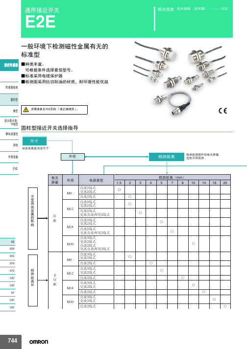
接近开关是一种无需与运动部件进行机械直接接触而可以操作的位置开关,当物体接近开关的感应面到动作距离时,不需要机械接触及施加任何压力即可使开关动作,从而驱动直流电器或给计算机(plc)装置提供控制指令。
接近开关是种开关型传感器(即无触点开关),它既有行程开关、微动开关的特性,同时具有传感性能,且动作可靠,性能稳定,频率响应快,应用寿命长,抗干扰能力强等、并具有防水、防震、耐腐蚀等特点。
产品有电感式、电容式、霍尔式、交、直流型。
接近开关又称无触点接近开关,是理想的电子开关量传感器。
当金属检测体接近开关的感应区域,开关就能无接触,无压力、无火花、迅速发出电气指令,准确反应出运动机构的位置和行程,即使用于一般的行程控制,其定位精度、操作频率、使用寿命、安装调整的方便性和对恶劣环境的适用能力,是一般机械式行程开关所不能相比的。
它广泛地应用于机床、冶金、化工、轻纺和印刷等行业。
在自动控制系统中可作为限位、计数、定位控制和自动保护环节等。
欧姆龙cp1w-cif12。
omron E2E通用接近开关 说明书
10mm 8mm
E2E-X10D1S-M1
D
——
—
E2E-X8MD1S-M1
D
——
—
M18
14mm
E2E-X14MD1S-M1
D
——
—
M30
20mm
E2E-X20MD1S-M1
D
——
—
M8
2mm
M12
ሣ㬑
M12 3mm
E2E-X2D1-M1G
A E2E-X2D2-M1G
D
E2E-X3D1-M1G *1
㾦ൟ
ᬒ఼ߚ行 Ё㒻ൟ
M30
10mm
无
M8
4mm
䴲ሣ㬑
M12
8mm
M18
14mm
E2E-X10D1-N E2E-X4MD1 E2E-X8MD1 E2E-X14MD1
*1*2*3 *2*3 *1*2*3 *1*2*3
E2E-X10D2-N E2E-X4MD2 E2E-X8MD2 E2E-X14MD2
ሣ㬑
1.5mm
E2E-X1R5E1-M3
M8 䴲ሣ㬑
M8 2mm
E2E-X2ME1-M3
输出形态PNP NO E2E-CR8B1 E2E-X1B1 E2E-C1B1 E2E-X1R5F1 E2E-X2F1 E2E-X5F1 E2E-X10F1 E2E-X2MF1 E2E-X5MF1 E2E-X10MF1 E2E-X18MF1
Ⳉ⌕2㒓ᓣ
ƻ ƻ
Ⳉ⌕3㒓ᓣ M18 Ѹ⌕2㒓ᓣ
Ⳉ⌕2㒓ᓣ
ƻ ƻ
Ⳉ⌕3㒓ᓣ M30 Ѹ⌕2㒓ᓣ
Ⳉ⌕2㒓ᓣ
ƻ ƻ
744
E2E
⬉⑤䕧ߎ Փ⫼⦃๗
欧姆龙 D5F 高精度型光学开关 产品手册
<粘合剂>
陶瓷片以环氧树脂粘合, 后者可能因切割油或热溶剂产生退化。 在 最糟的情况下,陶瓷片可能脱落。陶瓷片可对抗部分切割油或丙 酮。在使用D5F前请检查操作环境。
ܡ䌍 ⬉䆱
䆶⬉䆱
400-820-4535
᳔ᮄֵᙃ
4
购买欧姆龙产品的客户须知
购买时的注意事项
D5F-2B@0
D5F-3C@0
㻤㡆 DC12̚24V 㻤㡆 DC12̚24V ݙ䚼⬉䏃 ON˄ᣝ˅ OFF ҂ ϡ҂ ݙ䚼⬉䏃 100 mAҹϟ 咥㡆䕧ߎ 㪱㡆0V
咥㡆䕧ߎ 㪱㡆0V 100 mAҹϟ
ᣛ冫♃ ˄㑶㡆LED˅
ᣛ冫♃ ˄㑶㡆LED˅
偅ࡼᴚ˖
偅ࡼᴚ˖
ON˄ᣝ˅ OFF
䕧ߎԧㅵ˖ ON ˄䋳䕑˅ OFF ᣛ冫♃˖ (LED)
● 关于使用环境
操作环境对D5F有重要影响。在各种切割油、溶剂或气体环境中使 用D5F之前,请咨询您的欧姆龙代表处。 已对下列12种切割油进行过测试。 如需在其他环境使用, 如其他切 割油、溶剂和气体中,请咨询您的欧姆龙代表处。 切割油 Yushiron油 No. 7 和No. 21 Yushiron切割 UB-75和G-55 EC-50, CN-102, MIC-2, Yushiroken MIC-10和S-52 Emulcut No.10 CosmoCool X106 Cool CH 制造商 Yushiro化学工业有限公司 Yushiro化学工业有限公司 Yushiro化学工业有限公司 Kyodo Yushi 有限公司 Cosmo油有限公司 Idemitsu Kosan有限公司
规格
■ 额定规格
电源电压 输出电流 功耗 漏电流 残留电压 DC12~24V±10%,波纹(p-p):10%以下 100mA以下 30mA以下 0.15mA以下 2V以下
Omron E2Q6 矩形接近传感器说明书

1many directions.Ordering InformationSensors [Refer to Dimensions on page 6]DC ModelsAccessories (Sold Separately)Recommended Cable Gland (ST Type) (Manufactured by LAPP)Purchase a cable gland to maintain a water-resistant structure.Dimensions (Unit: mm)Note:A seal packing is not included.Note:Purchase a seal packing to maintain water resistance.For the most recent information on models that have been certified for safety standards, refer to your OMRON website.Refer to Safety Precautions on page 4.Product number ColorScrew size Applicable cable outer diameterST-M20 ⨯ 1.5Black M20 ⨯ P1.57 to 13 dia.Applicable seal packingGPM20For details or to make purchases, contact your OMRON sales representative.2Ratings and Specifications*1.The response frequency is an average value. Measurement conditions are as follows: standard sensing object, a distance of twice the standardsensing object, and a set distance of half the sensing distance.*2.When the recommended cable gland is used.ShieldingShielded Unshielded ItemModelE2Q6-N20☐3-HE2Q6-N30M ☐3-HSensing distance 20 mm ±10%30 mm ±10%Set distance 0 to 16 mm0 to 24 mmDifferential travel 15% max. of sensing distanceDetectable object Ferrous metal (The sensing distance decreases with non-ferrous metal. Refer to Engineering Data (Reference Value) on page 3.)Standard sensing object Iron, 60 ⨯ 60 ⨯ 1 mm Iron, 90 ⨯ 90 ⨯ 1 mm Response frequency *1150 Hz100 HzPower supply voltage (operating voltage range)10 to 30 VDC, including 10% ripple (p-p)Current consumption 20 mA max.Control output Load current 200 mA max.Residual voltage2 V max. (at 200 mA load current)Indicators Power indicator (green), detection indicator (yellow)Operation mode NO + NCProtection circuitsPower supply reverse polarity protection, output reverse polarity protection, and load short-circuit protectionAmbient temperature range Operating and storage: -25 to 70︒C (with no icing or condensation)Ambient humidity range Operating and storage: 35% to 95% (with no condensation)Temperature influence ±15% max. of sensing distance at 23︒C in the temperature range of -25 to 70︒C Voltage influence ±2% max. of sensing distance at 24 VDC in the range of 24 VDC ±15%±2% max. of sensing distance at 12 VDC in the range of 12 VDC ±15%Insulation resistance 50 M Ω min. (at 500 VDC) between current-carrying parts and case Dielectric strength1,000 VAC, at 50/60 Hz for 1 min. between current-carrying parts and case Vibration resistance (destruction)10 to 55 Hz with a 1.5-mm double amplitude in X, Y, and Z directionsShock resistance (destruction)300 m/s 2 3 times each in six directions Degree of protection IEC IP67 *2Connection methodTerminal block Weight (packed state/Sensor only)Approx. 250 g/approx. 230 gMaterials CasePolyamide (PA)Sensing surface Polyamide (PA)Terminal base Polyamide (PA)AccessoriesInstruction manual3I/O Circuit DiagramsNPNPNPShielded Models E2Q6-N20☐3-H Unshielded Models E2Q6-N30M ☐3-HSide length of sensing object: d (mm)D i s t a n c e X (m m )510152025Side length of sensing object: d (mm)4Safety PrecautionsBe sure to read the precautions for all models in the website at: http///.Indication and Meaning for Safe UseThis product is not designed or rated for direct-ly or indirectly ensuring safety of persons.Do not use it for such a purpose.Never use this product with an AC power sup-ply. Otherwise, explosion may result.The following precautions must be observed to ensure safe operation.1.Do not use the product in an environment where flammable orexplosive gas is present.2.Do not attempt to disassemble, repair, or modify the product.3.Power Supply VoltageDo not use a voltage that exceeds the rated operating voltage range. Applying a voltage that is higher than the operating voltage range may result in damage or burnout.4.Incorrect WiringBe sure that the power supply polarity and other wiring is correct. Incorrect wiring may cause explosion or burnout.5.Connection without a LoadIf the power supply is connected directly without a load, the internal elements may explode or burn. Be sure to insert a load when connecting the power supply.6.Dispose of this product as industrial waste.UL CertificationThis product is certified for UL standards, but the certification is not applicable to metal piping to the conduit section.For UL applications, use a certified cable grip.Operating Environment1.Do not install the product in the following locations.Doing so may result in product failure or malfunction.(1)Outdoor locations directly subject to sunlight, rain, snow,water droplets, or oil.(2)Locations subject to atmospheres with chemical vapors, inparticular solvents and acids.(3)Locations subject to corrosive gases.(4)Locations subject to shocks or vibration.2.The Sensor may malfunction if used near ultrasonic cleaningequipment, high-frequency equipment, transceivers, cellular phones, inverters, or other devices that generate a high-frequency electric field. Please refer to the Precautions for Correct Use of Photoelectric Sensors on the OMRON website () for typical measures.ying the Proximity Sensor wiring in the same conduit or duct ashigh-voltage wires or power lines may result in incorrect operation and damage due to induction. Wire the Sensor using a separate conduit or independent conduit.4.CleaningNever use thinner or other solvents. Otherwise, the product surface may be dissolved.5.Do not subject the Sensor to strong shock. Otherwise, the SensorHead may be damaged.Power ONThe Sensor is ready to sense an object within 300 ms after turning the power ON. If the load and Sensor are connected to different power supplies, always turn ON the Sensor power first.Power OFFOutput pulses may occur when the power supply is turned OFF. Turn OFF the power supply to the load or load line first.Effects of Surrounding MetalsWhen the Proximity Sensor is embedded in metal, make sure that the clearances given in the following table are maintained.(Unit: mm)Indicates a potentially hazardous situation which, if not avoided, will result in minor or moderate injury, or may result in serious injury or death. Additionally there may be significant property damage.Precautions for Safe Use Supplementary comments on what to do or avoid doing, to use the product safely.Precautions for Correct UseSupplementary comments on what to do or avoid doing, to prevent failure to operate, or undesirable effect on product performance.WARNINGPrecautions for Safe UsePrecautions for Correct UseModelA B C D E F E2Q6-N20 3-H 00001060E2Q6-N30M 3-H4025402090BABCEDEFE2Q65Mutual InterferenceIf more than one Proximity Sensor is installed face-to-face or side-by-side, make sure that the distances between two units adjacent to each other are the same as or larger than the corresponding values shown in the following table.(Unit: mm)Tightening TorqueTighten bolts and screws with the specified torque.Switching the Sensing Direction1. Remove two screws.2. Lifting the sensing surface separates it from the case.3. When positioning the sensing surface to the side, rotate it to the required position, then fit it into the case. (The possible positions are 0, 90, 180, and 270 . Do not forcefully rotate the sensing surface.)4. Secure it with the screws.ModelA B E2Q6-N20 3-H 170120E2Q6-N30M 3-H280200Between case and terminal 1.8 N·m Terminal screws1.0 N·mABA(1)E2Q6In the interest of product improvement, specifications are subject to change without notice.Cat. No. F17E-EN-01OMRON EUROPE B.V.Wegalaan 67-69,NL-2132 JD, Hoofddorp, The NetherlandsPhone:+31 23 568 13 00Fax:+31 23 568 13 88industrial.omron.euDimensionsSensorsE2Q6-N20E3-H E2Q6-N20F3-H E2Q6-N30ME3-H E2Q6-N30MF3-H(Unit: mm)Tolerance class IT16 applies to dimensions in this data sheet unless otherwise specified.Mounting Hole Dimensions。
接近开关(欧姆龙)方柱标准型TL_N_TL_Q_TL_G
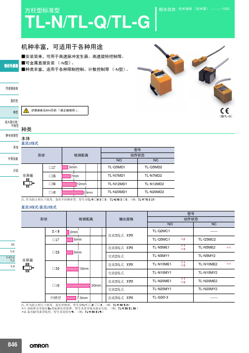
TL-N20ME□、 TL-N20MY□
检测距离
5mm±10%
10mm±10%
20mm±10%
设定距离
0~4mm
0~8mm
0~16mm
应差距离
检测距离的15%以下
检测物体
磁性金属 (非磁性金属回降低检测距离。参考 「特性数据」→851、 852页)
标准检测物体 铁30×30×1mm
铁40×40×1mm
1V以下(负载电流100mA 及导线长2m时)
检测显示 (红色)
10mA以下(DC24V时)
NPN集电极开路 50mA以下(DC30V以下)
1V以下(负载电流50mA 及导线长2m时)
DC12~24V 脉动(p-p)5%以下
2mA以下(DC24V、无负载时) NPN集电极开路 20mA以下
——
——
䴭⬉ᆍ䞣ൟ ݊Ҫ
检测面
耐热ABS
附件
E型:金属安装配件、使用说明书 Y型:使用说明书
*1. 直流开关部的响应频率为平均值。测定条件为:有标准检测物体时,检测体的间隔和为检测物体的2倍,设定距离为检测距离的1/2。 *2. E型(直流开关型)可用DC24V±10%(平均值)的全波整流电源。
䖥Ӵᛳ఼
Ӵᛳ఼ᣛफ ᷅ൟ 㾦ൟ ᬒ఼ߚ行 Ё㒻ൟ 䴭⬉ᆍ䞣ൟ ݊Ҫ ೈ䆒 ҟ㒡
保护结构
连接方式
质量 (捆包状 态)
IEC规格 IP67 〔JEM规格IP67g (耐浸型、耐油型)〕 导线引出式(标准导线长2m)
约45g
约145g
约170g
外壳 材质
检测面
耐热ABS
附件
使用说明书
金属安装配件、使用说明书
OMRON接近开关e2e-x7d1-n

OMRON接近开关e2e-x7d1-n
接近开关是一种无需与运动部件进行机械直接接触而可以操作的位置开关,当物体接近开关的感应面到动作距离时,不需要机械接触及施加任何压力即可使开关动作,从而驱动直流电器或给计算机(plc)装置提供控制指令。
接近开关是种开关型传感器(即无触点开关),它既有行程开关、微动开关的特性,同时具有传感性能,且动作可靠,性能稳定,频率响应快,应用寿命长,抗干扰能力强等、并具有防水、防震、耐腐蚀等特点。
产品有电感式、电容式、霍尔式、交、直流型。
接近开关又称无触点接近开关,是理想的电子开关量传感器。
当金属检测体接近开关的感应区域,开关就能无接触,无压力、无火花、迅速发出电气指令,准确反应出运动机构的位置和行程,即使用于一般的行程控制,其定位精度、操作频率、使用寿命、安装调整的方便性和对恶劣环境的适用能力,是一般机械式行程开关所不能相比的。
它广泛地应用于机床、冶金、化工、轻纺和印刷等行业。
在自动控制系统中可作为限位、计数、定位控制和自动保护环节等。
OMRON接近开关e2e-x7d1-n。
欧姆龙A9T开关中文说明书

1Subminiature Toggle Switch A9TA9TSubminiature Toggle SwitchDouble-sided clip contact mechanism combined with see-saw action.•Gold-plated clip contact and cleaning mechanisms ensure high reliability.•Specially designed to prevent grease entry into the contact portion.•Sealed against flux entry.•Washable, equivalent to IP64 (IEC-60529).■List of Models●DIP Terminal Models●Right Angle Terminal ModelsRoHS CompliantSecurity Control BoardsElectric Power Instrumentation Program ControllersTypical ApplicationsSubminiature Toggle Switch A9T2●Vertical Mount Terminal ModelsNote:1.(ON) shows Momentary.2.Switching Functions show the view from the side of Type and Brand name marking.3.Actuator does not stop at "-" position.■Ratings/CharacteristicsRatings50 mA at 60 VAC/DC, 1 μA (minimum current) at 20 mVAC/DC Ambient operating temperature -20 to +80 °C 60% RH max. (with no icing or condensation)Ambient operating humidity 45 to 85%RH (at +5 to +35 °C )Insulation resistance 1,000 M Ω min. (Initial value)Contact resistance 50 m Ω max. (Initial value)Dielectric strength 500 VAC for 1 min between terminals, between terminals and ground Vibration resistance Malfunction 10 to 55 Hz,1.5-mm double amplitude Shock resistance Malfunction 500 m/s 2 min.Durability Mechanical 50,000 operations min.Electrical50,000 operations min.Operating force0.49 to 3.43 N {50 to 350 gf}WeightDIP TerminalStandard: 0.8 g Right Angle Terminal Standard: 1 g Vertical Mount Terminal Standard: 1 g3Subminiature Toggle Switch A9T■Dimensions (Unit: mm)●DIP Terminal ModelsNote:No. (1) and (3) terminals in the SPDT models are dummys to support the Switch case.●Right Angle Terminal Models●Vertical Mount Terminal ModelsNote:Unless otherwise specified, a tolerance of ±0.4 mm applies to all dimensions.PCB Dimensions (Top View)■Switching Function / Internal ConnectionsNote:(ON) shows Momentary.■Safety PrecautionsBe sure to read the Safety precautions common to all PCB-mount Manual Switches for correct use.Subminiature Toggle Switch A9T4。
e3z-d62欧姆龙
e3z-d62欧姆龙
接近开关是一种无需与运动部件进行机械直接接触而可以操作的位置开关,当物体接近开关的感应面到动作距离时,不需要机械接触及施加任何压力即可使开关动作,从而驱动直流电器或给计算机(plc)装置提供控制指令。
接近开关是种开关型传感器(即无触点开关),它既有行程开关、微动开关的特性,同时具有传感性能,且动作可靠,性能稳定,频率响应快,应用寿命长,抗干扰能力强等、并具有防水、防震、耐腐蚀等特点。
产品有电感式、电容式、霍尔式、交、直流型。
接近开关又称无触点接近开关,是理想的电子开关量传感器。
当金属检测体接近开关的感应区域,开关就能无接触,无压力、无火花、迅速发出电气指令,准确反应出运动机构的位置和行程,即使用于一般的行程控制,其定位精度、操作频率、使用寿命、安装调整的方便性和对恶劣环境的适用能力,是一般机械式行程开关所不能相比的。
它广泛地应用于机床、冶金、化工、轻纺和印刷等行业。
在自动控制系统中可作为限位、计数、定位控制和自动保护环节等。
e3z-d62欧姆龙。
- 1、下载文档前请自行甄别文档内容的完整性,平台不提供额外的编辑、内容补充、找答案等附加服务。
- 2、"仅部分预览"的文档,不可在线预览部分如存在完整性等问题,可反馈申请退款(可完整预览的文档不适用该条件!)。
- 3、如文档侵犯您的权益,请联系客服反馈,我们会尽快为您处理(人工客服工作时间:9:00-18:30)。
Ẕ⌟⠽ԧⱘ䖍䭓d(mm)
E2K-X8M
䎱 行 10 X嗻 嗼 mm 8
ƶ50 t
X 6
4
2
0
5
10
ഄ䞥ሲ
䴲ഄ䞥ሲ ⦏⩗ 㣃䜮˄ᷥ㛖˅
ϭ⛃䝌˄ᷥ㛖˅
15
20
25
Ẕ⌟⠽ԧⱘ䖍䭓t(mm)
E2K-X15M
䎱 行 25 X嗻 嗼 mm 20
ƶd t=3mm
X
15
10
5
ഄ䞥ሲ
䴲ഄ䞥ሲ
⦏⩗ 㣃䜮˄ᷥ㛖˅ ϭ⛃䝌˄ᷥ㛖˅
1
E2K-C
⦏⩗ 㣃䜮˄ᷥ㛖˅
E2K-X E2K-F
0
5
10
15
20
25
Ẕ⌟⠽ԧⱘ䖍䭓t(mm)
E2K-L
E2KQ-X
E2J
E2K-X8M
䎱 行 10
X嗻 嗼 mm
8
ƶd t=3mm
X
ഄ䞥ሲ
6 䴲ഄ䞥ሲ
4
⦏⩗ 2
㣃䜮˄ᷥ㛖˅
ϭ⛃䝌˄ᷥ㛖˅
0
10 20 30 40 50 60 70
圆柱型
E2K-X
检测金属以外的物体。 通用螺纹安装型
䖥Ӵᛳ఼ ■金属以外,还可检测水、油、玻璃、塑料等非金属。 ■螺钉切割型。具有M12/M18/M30型等丰富的种类。 安装方便。 ■检测距离固定,非调整型。
Ӵᛳ఼ᣛफ
᷅ൟ
详情请参阅926页的 「请正确使用」。
㾦ൟ
ᬒ఼ߚ行
Ё㒻ൟ 种类
䴭⬉ᆍ䞣ൟ 本体
ˆ2. Eൟ˖Ẕ⌟ᰒ冫♃˄㑶˅ Yൟ˖ࡼᰒ冫♃˄㑶˅
䖥Ӵᛳ఼
Ӵᛳ఼ᣛफ ᷅ൟ 㾦ൟ ᬒ఼ߚ行 Ё㒻ൟ 䴭⬉ᆍ䞣ൟ ݊Ҫ ೈ䆒 ҟ㒡
0 10 20 30 40 50 60 70 Ẕ⌟⠽ԧⱘ䖍䭓d(mm)
E2K-X15M
䎱 行 25
X嗻 mm嗼 20
ƶ50 t
X
15
10
5
ഄ䞥ሲ
䴲ഄ䞥ሲ ⦏⩗
㣃䜮˄ᷥ㛖˅ ϭ⛃䝌˄ᷥ㛖˅
0
5
10
15
20
25
Ẕ⌟⠽ԧⱘ䖍䭓t(mm)
924
E2K-X
泄漏电流特性
E2K-X□MY
⊘ ⓣ
2.0
⬉
⌕嗻
m嗼 A
φ12.5
+0.5 0
φ18.5
+0.5 0
φ30.5
+0.5 0
φ28.1
ˆ1
M30×1.5
2-㋻㶎↡ 2-ൿ
ˆ1. Eൟ˖PVC㒱㓬ᔶᇐ㒓 φ6ǃ3㢃 ˄ᇐԧ䴶鳥˖0.5mm2ǃ㒱㓬Ⳉᕘ˖φ1.9mm˅ ᷛޚ2m
Yൟ˖PVC㒱㓬ᔶᇐ㒓 φ6ǃ2㢃 ˄ᇐԧ䴶鳥˖0.5mm2ǃ㒱㓬Ⳉᕘ˖φ1.9mm˅ ᷛޚ2m
警告
本产品不可以作为人体保护检测使用。
䖥Ӵᛳ఼
使用注意事项
请不要在超过额定的使用范围和环境下使用。
●设计时
Ӵᛳ఼ᣛफ 周围环境 接触水、油、药品等,或在结露状态使用时,有可能将它们当
作检测物体而造成误动作,应予以避免。 ᷅ൟ E2K-X15M尤其对电介质灵敏度高,少量的水、油也会有影
响。 㾦ൟ
周围金属的影响
ᬒ఼ߚ行
Ё㒻ൟ
䎱 行5
X嗻
ƶd t=3mm
䴭⬉ᆍ䞣ൟ
嗼 mm 4
X
ഄ䞥ሲ
݊Ҫ
3
ೈ䆒
2
䴲ഄ䞥ሲ
1
ҟ㒡
⦏⩗
㣃䜮˄ᷥ㛖˅
0
10 20 30 40 50 60 70
Ẕ⌟⠽ԧⱘ䖍䭓d(mm)
检测物体的厚度与材质的检测距离
E2K-X4M
䎱 行
5
X嗻
嗼 mm 4 3
ƶ50 t
X
ഄ䞥ሲ
䴲ഄ䞥ሲ 2
0.78N·m 2N·m
注. E2K-X4M□□附有专用固紧工具,请使用专用工具进行固紧。
●其他 有关有机溶剂的问题 外壳材质为耐热ABS,请勿与有机溶剂及含有有机溶剂的液体 接触。
E2K-C 相互干扰 相向或并列配置时,请超过下表所示距离的范围内使用。
E2K-X
E2K-F E2K-L E2KQ-X
时间图
Ẕ⌟⠽ԧ
᳝
᮴
䋳䕑
ࡼ ԡ
҂♃ ࡼᰒ冫♃˄㑶˅ ♃
Ẕ⌟⠽ԧ
᳝
᮴
䋳䕑
ࡼ ԡ
҂♃ ࡼᰒ冫♃˄㑶˅ ♃
输出回路
䖥 ᓔ݇ Џಲ䏃
㻤 䋳䕑
㪱
E2K-C E2K-X E2K-F E2K-L E2KQ-X E2J
925
E2K-X
请正确使用
详情请参见共通注意事项(→1337页),有关订货时的须知请参见(→F-4页)。
显示灯
E型:检测显示 (红色) Y型:动作显示 (红色)
动作状态 (接近检测物体时)
E1、 Y1型:NO E2、 Y2型:NC
详情请参照 「输入输出段回路图」的时间图表→925页
保护回路
E型:逆接保护、浪涌吸收、 Y型:浪涌吸收
周围环境温度
动作时、保存时:各-25~+70℃ (不结冰、结露)
动作时、保存时:各-10~+55℃ (不结冰、结露)
E型:DC12~24V(DC10~30V) Y型:AC100~220V(AC90~250V)
消耗电流
E型:15mA以下
泄漏电流
Y型:2.2mA以下 请参阅→925页
控制 输出
开关容量 残留电压
E型:200mA以下 *2 Y型: 10~200mA E型:1V以下 (负载电流200mA、导线长2m时) Y型:详情请参照 「特性数据」→925页
相互干扰 型号
A
B
尺寸
(单位: mm)
A
B
E2J E2K-X4M
80 70
E2K-X8M
150 110
E2K-X15M
300 200
926
外形尺寸
E2K-X4ME□ E2K-X4MY□
CAD᭄
E2K-X8ME□ E2K-X8MY□
E2K-X
(单位:mm) CAD᭄
80 φ21
60 17
20 4 4 φ10.7
ᬒ఼ߚ行 埋入金属中时,应于超过下表所示距离的范围使用。另外,金 Ё㒻ൟ 属以外的物体(树脂等)也会有影响,因此有金属物时请按下
表所示的值保持一定距离以上使用。 䴭⬉ᆍ䞣ൟ
l
有关检测物体 检测物体为非接地金属和电介质 (体)时,动作距离会减小。 ·检测物体的材质
尽管几乎所有的物体都可以检测,但会因检测物体的电性能 (导电率、介电常数) ,或吸水状态、体积等因素而使检测 距离有所不同。对于接地金属则可获得最大检测距离。 ·由于也含有不能间接检测的情况,请在确认的基础上使用。
型号 动作状态
NC E2K-X4ME2 E2K-X4MY2 E2K-X8ME2 E2K-X8MY2 E2K-X15ME2 E2K-X15MY2
E2K-C E2K-X E2K-F E2K-L E2KQ-X
E2J
922
额定值/性能
E2K-X
项目
型号
E2K-X4ME□、 E2K-X4MY□
E2K-X8ME□、 E2K-X8MY□
高频电场的影响 当附近有可以产生高频电场的超声波洗涤装置、高频发生装 置、无线电收发机·移动电话及变频器等时会造成错误动作。 作为代表性的对架可参阅光电传感器的共通注意事项 「关于干扰」→1312页。
●安装时 紧固螺母时用力勿过大,且一定要使用止扣垫圈。
݊Ҫ ೈ䆒
φd
nm
ˆ
ҟ㒡
ᖙ乏ഄ
䞥ሲԧ
*金属体时接地时又不接地时易造成动作的不稳定,因此必须接地。
䖥Ӵᛳ఼
Ӵᛳ఼ᣛफ ᷅ൟ 㾦ൟ ᬒ఼ߚ行 Ё㒻ൟ 䴭⬉ᆍ䞣ൟ ݊Ҫ ೈ䆒 ҟ㒡
E2K-C E2K-X E2K-F E2K-L E2KQ-X E2J
923
E2K-X
特性数据 (代表例)
检测领域 (接地金属板)
E2K-X4M
䎱 行
18
X嗻 16
m嗼m14
E2K-X15M
X Y
䖥Ӵᛳ఼
12
E2K-X15ME□、 E2K-X15MY□
检测距离
4mm±10%
8mm±10%
15mm±10%
设定距离 *1
0~2.8mm
0~5.6mm
0~10mm
应差距离
检测距离的4~20%
检测物体
导体及电介质体
标准检测物体
接地金属板 50×50×1mm
应答频率
E型:100Hz、 Y型:10Hz
电源电压 *2 (使用电压的范围)
䋳䕑⬉⌕(mA)
E2K-X□MY□
䋳
䕑 240
⬉
य़
䕧ߎ⅟⬭⬉य़
V嗻L 200
V嗼
160
120
80
AC200V时
ON
V
VL A
䖥Ӵᛳ఼
AC200V
40
䋳䕑⅟⬭⬉य़ 0 3 5 10
Ӵᛳ఼ᣛफ
OFF
20 30 50 100 200 ᷅ൟ䋳䕑⬉来自(mA)输入输出段回路图
直流3线式
动作状态
型号
E2K-X4ME1 NO E2K-X8ME1
10
ᷛޚẔ⌟⠽ԧ ഄ䞥ሲᵓ
50×50×1mm
8
6
E2K-X8M
4
Ӵᛳ఼ᣛफ
2
E2K-X4M
᷅ൟ
0 -25 -20 -15
-10 -5 0 5 10 E2K-X4MẔ⌟༈