HMILITE_012007(英文)
工贝HMI200系列一体机 使用说明书
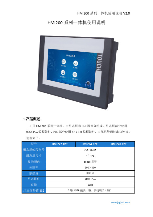
HMI200系列一体机使用说明1.产品概述工贝HMI200系列一体机,由组态屏和PLC两部分组成,组态屏部分使用MCGS Pro编程软件,PLC部分使用S7V4.0编程软件,内部已经通过串口连接。
选型如下:2.接线图3.编程说明1.一体机由组态屏和PLC两部分组成,组态屏部分使用MCGS Pro编程软件2.组态屏部分和PLC部分内部通过串口固定连接,组态屏占用的是COM1,选择如下图PLC占用的是PORT1。
两者通讯使用PPI协议,PLC端无需设置和编程,一般使用默认即可。
4.模拟量接口定义5.4-20mA两线制、三线制变送器接线示意图6.晶体管输出内部示意图7.继电器输出内部示意图8.常见问题8.1组态屏编程选择哪个型号?PLC编程选择哪个型号?答:组态屏编程软件用MCGS Pro版本,型号选择TPC7032Kt。
PLC编程软件用Step7V4.0,型号选择CPU226CN。
8.2背后的网口是属于PLC的还是组态屏的?IP地址是多少?答:属于组态屏的。
可以通过网口给组态屏下载程序,也可以实现组态屏和其它设备通讯。
组态屏默认IP是200.200.200.190。
断电重启时,连续点击屏幕可进入启动属性界面,点系统维护,点系统维护,点设置系统参数,点IP地址标签页,可进行修改。
8.3背后的USB口都有什么作用?答:属于组态屏接口,用mcgs软件制作U盘综合功能包,可以给组态屏下载程序。
也可以插鼠标或者键盘。
8.4背后的DB9接口是如何定义的?1:机壳接地2:GND3:PLC的PORT0_485信号A4:组态屏的COM2_485信号A5:GND6:+5V7:+24V8:PLC的PORT0_485信号B9:组态屏的COM2_485信号B8.5右下角有两个485通讯口,如何使用?答:标号C3的485通讯口,属于组态屏部分,在组态屏编程时选择COM3。
标号P2的485通讯口,属于PLC部分,默认PPI协议,波特率9600,地址2。
触摸屏HMI操作说明书
昆明烟厂太阳能预热洗涤热水系统操作员站HMI操作简易说明书(2011-8)操作员站 (1)HMI操作简易说明书 (1)HMI系统概述 (3)软件系统架构 (3)窗口操作介绍 (3)登录窗口 (3)功能操作栏 (3)常规主画面 (4)用户注销 (4)确认退出对话框 (5)报警浏览窗口 (5)报警历史程序窗口 (6)模拟量趋势 (7)操作记录查询画面 (8)标准模块窗口 (8)工程参数设定画面 (8)电机操作画面 (10)HMI系统概述软件系统架构昆明烟厂太阳能预热洗涤热水系统采用1个Pannelview触摸屏做操作员站和工程师站,HMI系统采用FTView上位机软件,通过RS232链接Controllogix,采用RSLinx Enterprise OPC连接方式获取PLC中的数据。
窗口操作介绍登录窗口图2 登录窗口当操作员站触摸屏启动后,会自动加载HMI程序,程序启动后,会提示输入操作员用户名和密码,只有有权限登录的人员才能登录本系统。
功能操作栏图3 功能操作栏所有主画面的底部均为此操作栏,用于一些功能画面的导航。
点击左边4个按钮将弹出菜单窗口栏,用于直接导航切换到相应到画面。
点击历史趋势将切换到历史趋势窗口,点击状态图将切换到当前工艺主画面。
点击操作参数按钮,将显示可以操作的水泵、电磁阀启停、开闭。
点击工程参数按钮将切换到工程参数设定画面。
常规主画面图4 常规主画面本画面为系统中较常规的画面,集中了绝大部分画面元素。
大部分画面元素是根据PID 画面所制,每个监控点都有一个KKS编码与之对应,点击画面上的不同监控点,会弹出相应的操作小窗口用于操作。
如果本画面中有相应的顺控子组操作,则会放置相应的顺控操作按钮。
用户注销图5 确认注销对话框当点击任意一个主画面上的用户注销按钮时,将注销当前登录用户,为只能查看状态,不能做任何操作的权限画面。
当用户重新登录,才能根据分配的用户权限操作或设定工程参数。
权限分配是按照操作员组来划分的,系统中预留5个组,分别是管理员组,操作员组1,操作员组2,操作员组3,默认组,所有的用户分属于不同的组。
Eaton 7寸人机界面(HMI)说明书
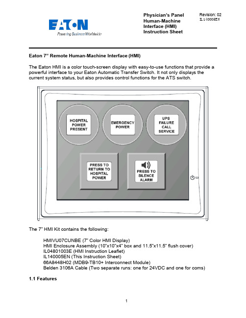
Physician’s Panel Human-Machine Interface (HMI) Instruction Sheet Revision: 02 IL140005ENEaton 7” Remote Human-Machine Interface (HMI)The Eaton HMI is a color touch-screen display with easy-to-use functions that provide a powerful interface to your Eaton Automatic Transfer Switch. It not only displays thecurrent system status, but also provides control functions for the ATS switch.The 7” HMI Kit contains the following:HMIVU07CUNBE (7” Color HMI Display)HMI Enclosure Assembly (10”x10”x4” box and 11.5”x11.5” flush cover)IL04801003E (HMI Instruction Leaflet)IL140005EN (This Instruction Sheet)66A8448H02 (MDB9-TB10+ Interconnect Module)Belden 3106A Cable (Two separate runs: one for 24VDC and one for coms)1.1 FeaturesThere are two types of features incorporated into the HMI: Status and Control. Below are lists of each:StatusHospital Power PresentEmergency PowerUPS Failure – Call ServiceWaiting to Retransfer to Hospital PowerAlarm Muted/Un-mutedControlManual Retransfer to Hospital Power buttonAlarm Silence button1.2 Set-up and WiringTo connect your HMI assembly to your Automatic Transfer Switch, simply follow the wiring diagram S002 (Sheet 3 of 5) or use this quick-reference guide.Each of the supplied Belden 3106A cables (two lengths of 30m) has three insulated wires and one ground connected to the shield of the cable. One cable is for 24VDC power; the other cable is for communications. Stickers are attached to each cable for identification.The UPS Alarm Contact wire max length/size is 92000 ft. (22AWG) to 370000 ft. (16AWG)All wire connections inside the HMI enclosure come pre-assembled from the factory. However, if the wire ever needs to be replaced or serviced, please refe rence the following information:Inside the HMI enclosure, the communication connector (Figure 1) connects to the HMI’s COM2 port (see item “B” on Figure 2). The module has screw-type terminal blocks to terminate the communication cable wiring. After the wires are installed, simply plug the adapter into COM2, and screw in both sides of the connector to the device. A picture of the adapter (Figure 1) is shown below. 24VDC power is done the same way. Wires are terminated in a green screw-type terminal block that plugs directly into the HMI. Termination points noted on drawing S002 (Sheet 3 of 5).Figure 1 - Serial Termination ModuleFigure 2 - HMI Rear-ViewThe communication setpoints on the ATC-300+ should be set from the factory as follows:Baud Rate: 9600Address: 01Terminated: Off (termination micro-switch on back side of ATC-300+)There is a hidden system menu in the HMI that allows the operator to change items like touch screen force, touch screen calibration, time & date, brightness & contrast, alarm and touch volume, and others. The HMI should be set up so the user will not have to adjust anything in the field. If a change is desired, open the HMI enclosure and press the small SYSTEM button (item “H” in Figure 2) on the back of the unit for threeseconds. This will take you to the system menu. The menus are self-explanatory, but if help is required, see instruction leaflet IL04802001E located in the plastic document pouch inside your ATS enclosure. After the adjustments have been made, simply push “Home”, followed by “Run”.1.3 Functional DescriptionThe HMI is programmed with one main screen which shows both status and control of the ATS unit. It also includes an audible alarm.Figure 3 - Main Screen (Indicators ON) Indicator #1Hospital Power Present – Green (ON), Gray (OFF)#4#5This indicator turns green when the main hospital power is present and available. It does not indicate that the ATS is connected to hospital power or not.Indicator #2Emergency Power – Red (ON), Gray (OFF)This indicator turns red when the ATS is connected to UPS backup power.Indicator #3UPS Failure Call Service – Flashing Yellow (ON), Gray (OFF)This indicator starts flashing yellow when the dry contact in the UPS system closes, indicating that there is a system failure at the UPS.Indicating Button #4Press To Return To Hospital Power – Flashing Blue (ON), Gray (OFF)This is a dual purpose indicator/button. The button will start flashing blue when the ATS unit is waiting to manually retransfer back to hospital power. To retransfer, simply press the button on the HMI screen, and the ATS unit will connect to hospital power. Pressing the button while it is gray will have no effect. Note: the transfer switch will automatically transfer back to Hospital Power if Emergency Power becomes unavailable while connected to Emergency Power. This is an automatic failsafe feature.Indicating Button #5Press to Silence/Un-Mute Alarm – Orange (ON), Gray (OFF)This button is used to silence the alarm tone when it is active. Pressing it will change the button color from gray to orange; the speaker icon will change to a muted symbol as well. To un-silence the alarm, press the button again. The alarm will continue to sound, and the button will change back to gray.AlarmsWaiting to Retransfer – Audible (Continuous Tone).The HMI will produce and audible alarm tone whenever the system is waiting for a user input to return to hospital power (Return to Hospital Power button is flashing blue). It will automatically go away as soon as the system transfers back to hospital powe r, or if the system is no longer waiting to return to hospital power. To manually silence the alarm tone, simply press the alarm silence button (Indicating Button #5).CAUTIONThis is a remote control device. Caution should be observed to make sure that appropriate procedures are in place when using manual retransfer. Appropriate procedures include, but are not limited to, switch doors being closed and latched, personnel knowledgeable of transfers, and other site safety recommended procedures.。
SIMATIC HMI HMI 设备操作说明说明书

SIMATIC HMI HMI 设备Unified 精智面板操作说明05/2022A5E46641284-ACSiemens AG Digital Industries Postfach 48 48 90026 NÜRNBERG 德国Ⓟ 05/2022 本公司保留更改的权利Copyright © Siemens AG 2022.保留所有权利法律资讯警告提示系统为了您的人身安全以及避免财产损失,必须注意本手册中的提示。
人身安全的提示用一个警告三角表示,仅与财产损失有关的提示不带警告三角。
警告提示根据危险等级由高到低如下表示。
危险表示如果不采取相应的小心措施,将会导致死亡或者严重的人身伤害。
警告表示如果不采取相应的小心措施,可能导致死亡或者严重的人身伤害。
小心表示如果不采取相应的小心措施,可能导致轻微的人身伤害。
注意表示如果不采取相应的小心措施,可能导致财产损失。
当出现多个危险等级的情况下,每次总是使用最高等级的警告提示。
如果在某个警告提示中带有警告可能导致人身伤害的警告三角,则可能在该警告提示中另外还附带有可能导致财产损失的警告。
合格的专业人员本文件所属的产品/系统只允许由符合各项工作要求的合格人员进行操作。
其操作必须遵照各自附带的文件说明,特别是其中的安全及警告提示。
由于具备相关培训及经验,合格人员可以察觉本产品/系统的风险,并避免可能的危险。
按规定使用 Siemens 产品请注意下列说明:警告Siemens 产品只允许用于目录和相关技术文件中规定的使用情况。
如果要使用其他公司的产品和组件,必须得到 Siemens 推荐和允许。
正确的运输、储存、组装、装配、安装、调试、操作和维护是产品安全、正常运行的前提。
必须保证允许的环境条件。
必须注意相关文件中的提示。
商标所有带有标记符号 ® 的都是 Siemens AG 的注册商标。
本印刷品中的其他符号可能是一些其他商标。
若第三方出于自身目的使用这些商标,将侵害其所有者的权利。
汇川技术IT7070 HMI用户手册说明书

苏州汇川技术有限公司Suzhou Inovanc e Technology Co,.Ltd地址:苏州市吴中区越溪友翔路16号全国统一服务电话:400-777-1260 网址:ht tp://服务与技术APP 官方微信PDF下载IT7070人机界面用户手册前言资料简介感谢购买苏州汇川技术有限公司(以下简称汇川技术)开发、生产的IT7000 系列HMI。
该产品采用高性能处理器,数据处理、响应速度更快。
该产品基于Linux,采用Android风格,为用户提供界面友好的交互式体验,支持自定义样式、VNC远程桌面、矢量格式图标、脚本编程等功能;支持通过USB或者以太网连接PC;支持Modbus 协议,能够实现自动高效的PLC通讯;支持插入U盘对HMI固件、画面程序、配方数据等进行更新。
此外,该产品编程具备离线模拟及在线模拟的功能,方便HMI程序调试与系统调试。
本手册主要描述IT7070机型的规格、特性及使用方法等内容,使用前敬请详细阅读,以便更清楚、安全地使用本产品。
关于本产品用户程序开发环境的使用及用户程序设计方法,请参考本公司发行的后台软件“InoTouch PAD”帮助文档。
软件版本请以汇川技术公司网站()最新公布为准。
面向的读者本手册面向以下读者对象:使用或了解汇川技术HMI产品系列的用户,包括:电气工程师、软件工程师、系统工程师。
初次使用对于初次使用本产品的用户,应先认真阅读本手册。
若对一些功能及性能方面有所疑惑,请咨询我公司的技术支持人员,以获得帮助,有利于正确使用本产品。
■安全声明1.在安装、操作、维护产品时,请先阅读并遵守本安全注意事项。
2.为保障人身和设备安全,在安装、操作和维护产品时,请遵循产品上标识及手册中说明的所有安全注意事项。
3.手册中的“注意”、“警告”和“危险”事项,并不代表所应遵守的所有安全事项,只作为所有安全注意事项的补充。
4.本产品应在符合设计规格要求的环境下使用,否则可能造成故障,因未遵守相关规定引发的功能异常或部件损坏等不在产品质量保证范围之内。
研华HMI产品使用手册

研华HMI产品FAQ中文手册声明:为方便广大用户对研华HMI产品的选型和使用,特Array编制本手册供中国大陆客户使用。
本手册仅供参考!研华免费服务热线:800-810-0345研华(上海)IAG客户服务部目 录第一章HMI产品常见术语总结 (3)第一节常见术语 (3)第二章AWS系列产品特性与使用 (5)第一节AWS-9124 (5)第二节 AWS-8259 (7)第三节 AWS-8430 (8)第四节 AWS-8420 (9)第五节 AWS-8248 (12)第六节 AWS-8124 (14)第三章 IPPC系列产品特性与使用 (15)第一节IPPC-9120/9150 (15)第二节IPPC-920/950 (17)第四章TPC系列产品特性与使用 (19)第一节TPC-1560T (19)第二节 TPC-1260T (21)第三节 TPC-1240T (24)第四节 TPC-650T (25)第五节 TPC-642SE (26)第五章 FPM系列产品特性与使用 (28)第一节 FPM-3120 (28)第二节 FPM-3150 (31)第三节 FPM-3155 (33)第四节 FPM-3175 (34)第五节 FPM-3220 (35)第六节 FPM-3250 (36)第六章PWS系列产品特性与使用 (38)第一节 PWS-1409/1419 (38)第一章 HMI产品常见术语第一节、 常见术语什么是OSD(On-Screen-Display)功能?在FPM-3120和AWS系列的某些产品中你可以清楚的看到几个薄膜按钮,选择其中的按钮可以在显示器上出现调整采单,用于调整色彩、行、场等,这种OSD功能便于用户对图象质量的调整。
实际上,在研华的HMI产品中,凡是支持直接VGA功能的产品,都支持这个功能,如AWS-8248,FPM-3150等。
什么是U?U是欧制标准尺寸单位,一般在IT行业常见于对计算机高度的衡量,1U=4.4445cm。
西门子HMI介绍
冗余功能:在运行系统中服务器互相监控,达到提早识别故障服务器的目的。 如果一台服务器出了故障,客户机将自动从故障服务器切换到仍在运行的服 务器上。这样保证监控和操作过程中所有客户机可用。出现故障时,激活的 服务器会继续将WinCC项目的所有消息和过程数据归档。故障服务器恢复在 线后,所有消息的内容、过程值以及用户归档将自动复制到恢复的服务器。
此处添加变量
7
2.3 画面制作
画面系统负责监控现场设备运行情况,用户通过相应操作可以监视现场情 况,并对现场设备进行开启,关闭等操作。
阀开启关闭
罐液位监控
8
2.4 报警处理
组态报警编辑器,可以对现场重要的设备输入点进行监控,如果此数据点 出现异常,则在报警画面上进行显示,便于操作人员快速进行故障排除等, 报警一般分为故障,警告,信息等
19
3.5 函数
Protool 编写简单函数, 实现特定功能。在画面组态中可以调用。
20
12
2.8 交叉索引
画面中所有的变量,所属位置,类型等
13
2.9 用户管理
设置相应密码级别,控制操作权限。
菲尼克斯电气HMI和工业PC机产品说明书
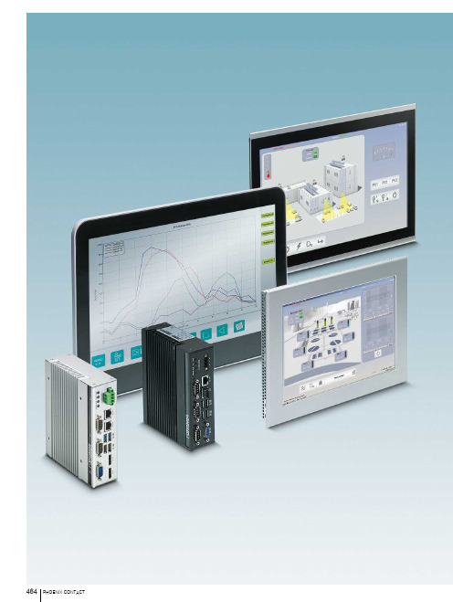
产品一览 466HMI适用于HTML5应用程序的HMI 468 适用于WebVisit软件的HMI 470 适用于Visu+的HMI 471工业PC机嵌入式PC机 474 机架式PC机 477 面板式PC机 481 触摸显示器 485用于移动应用的工业PC机平板式PC机 486 移动面板 487适于恶劣环境的HMI和工业PC机 488用于易爆区域的工业PC机 491用于海事应用的HMI 494HMI和工业PC机是系统和设备的关键所在。
可以通过整机IP65面板式PC机直接在现场操作,也可以采用强大的HMI 设备,高效设计出人机用户界面。
HMIHMI为人机界面的缩写,通过高效输入和监控,实现高性价比的自动化。
用户可根据自己的需求,选择适用于WebVisit、Visu+软件或HTML5应用的设备。
工业PC机工业PC机,简称IPC,同时具备现代化处理器的计算能力以及工业元件的坚固性与可靠性。
IPC配合相应的软件使用,是进行系统和机械控制、操作及监视的多功能高效解决方案。
用于移动场合的工业PC机面板式PC机是用于直观操作的先进的解决方案。
适于恶劣环境的HMI和工业PC机户外HMI 和工业PC 机适合暴露在外、受天气影响的环境。
这些设备采用IP67防护等级前面板、在阳光直射下可读的显示器和宽温设计,可用于充电站、废水处理厂等户外应用场合。
用于危险区域的工业PC机菲尼克斯电气提供通过IECEx和ATEX Zone 2/22认证的易爆区专用工业PC机。
用于海事应用的HMI针对严苛的船舶应用条件,菲尼克斯电气提供坚固耐用的操作和显示面板。
HMI和工业PC机适用于HTML5应用程序的HMI适用于WebVisit软件的HMI支持Visu+的HMI嵌入式PC机机架式PC机远距离连接方案软PLC面板式PC机触摸显示器用于移动场合的工业PC机适于恶劣环境的HMI和工业PC机用于危险区域的工业PC机海事HMI软件适于基础型HTML5应用适于严苛的HTML5应用电阻式触摸屏基本应用触摸屏电阻式触摸屏多点触控触摸屏可配置嵌入式PC机可配置嵌入式PC机可配置嵌入式PC机2U机架式PC机4U机架式PC机软件PLC软件PLC可配置面板PC机,采用Intel® Atom E3845技术可组态面板式PC可配置面板式PC可组态面板式PC可配置面板式PC触摸显示器,带投射电容式多点触控屏可配置平板PC机用于移动应用的工业PC机加固型Web面板加固型触摸屏可配置操作界面可配置嵌入式PC机可配置面板PC机,采用Intel® Atom E3845技术可配置面板式PC适于海事应用的可配置触摸屏。
- 1、下载文档前请自行甄别文档内容的完整性,平台不提供额外的编辑、内容补充、找答案等附加服务。
- 2、"仅部分预览"的文档,不可在线预览部分如存在完整性等问题,可反馈申请退款(可完整预览的文档不适用该条件!)。
- 3、如文档侵犯您的权益,请联系客服反馈,我们会尽快为您处理(人工客服工作时间:9:00-18:30)。
Manual 01/2007 Editionsolutions TRANSLINEGeneral Information Installation 1 2Solutions for Powertrain Global Settings andFunctionality3TRANSLINE – HMI Lite Visualization, Operation and Diagnosis Header and 4 Operator InformationManual OperationProduction Data5Manual6 Manufacturer DocumentationDiagnostics 7Hardware Diagnostics System Screen Forms8 9101112 AAppendix®SINUMERIK documentationPrinting historyBrief details of this edition and previous editions are listed below.The status of each version is indicated by the code in the "Remarks" columns.Status code in the "Remarks" column:A .... New documentation.B .... Unrevised reprint with new order number.C .... Revised edition with new status. Output 03.04 03.05 01.07Order no.Comment A&D MC - Extranet A&D MC - Extranet A&D MC - ExtranetA C CAdditional information is available on the Internet at: http://www.ad.siemens.de/sinumerikIt may be possible to run functions that are not described in this document in your controller. This does not, however, represent an obligation to supply such functions with a new control or when servicing.This documen was prepared with WinWord V 7.0 and Designer V 6.0 using the AutWinDoc documentation tool.Wir haben den Inhalt der Druckschrift auf Übereinstimmung mit der beschriebenen Hard- und Software geprüft. Dennoch kann es Abweichungen geben. Die Angaben in dieser Druckschrift werden re gelmäßig überprüft, und notwendige Korrekturen sind in dennachfolgenden Auflagen enthalten. Für Verbesserungsvorschläge sind wir dankbar.The reproduction, transmission or use of this document or its contents is not permitted without express written authority. Violation of this rule can lead to claims for damage compensation. All rights reserved, especially for granting patents or for GM registration. © Siemens AG 2007. Alle rechte vorbehalten.Technische Änderungen vorbehalten.Siemens AGTable of ContentsTable of Contents............................................................................... 5 1 General Information (11)1.1 Product overview 11 12 13 14 1.2 Provided screens 1.3 Basic knowledge 1.4 Hardware requirements1.5 Software requirements15 15 161.5.1 1.5.2 Configuration and Programming Software / Licenses Runtime software / licenses2 Installation (17)2.1 Unpacking the source project173 Global Settings and Functionality (19)3.1 Layout of the screens and basic screen elements 3.2 Menu structure 19 20 233.3 "Template" screen4 Header and Operator Information (25)4.1 Header25 25 26 26 27 27 27 4.1.1 4.1.2 4.1.3 4.1.4 4.1.5 4.1.6 Layout of the headerDisplay of current operating mode Status displayDisplay of the initial state Text boxesSign-of-life of the CPU 4.2 Operator information275 Manual Operating (29)5.1 Overview29 29 33 5.1.1 5.1.2 Layout and basic functionality of the manual operating screens Elements of the movement/function line5.2 Purpose of the individual manual operating screens 35 35 35 35 35 36 36 365.2.1 5.2.2 5.2.3 5.2.4 5.2.5 5.2.6 5.2.7 Manual operation Power up conditionSelecting/deselecting unitsSelecting/deselecting nut runnersSelecting/deselecting nut driver groups Selecting/deselecting cycle type User operating screen6 "Production Data" Screens (37)6.1 "Cycle times" screen37 37 6.1.1 Layout of the screen and functionality 6.2 "Workpiece counter" screen39 396.2.1 Layout of the screen and functionality7 Diagnostics (43)7.1 "Messages" screen and "Message archive" screen 7.1.1 Layout of the screen and functionality 43 43 7.2 "Interface" screen45 45 7.2.1 Layout of the screen 7.3 "Version" screen468 Hardware Diagnostics (47)8.1 "PROFIBUS" screen47 47 48 49 50 8.1.1 8.1.2 8.1.3 8.1.4 Layout of the "PROFIBUS overview" screen Overview: Diagnostic data of the slave Overview: Diagnosis network overview Detailed diagnostics 8.2 "Drive" screen52 52 53 54 8.2.1 8.2.2 8.2.3 "Drive status" screen "Drive alarms" screen "Drive position" screen8.3 "MOBY-I" screen55 55 56 8.3.1 8.3.2 Layout of the screen and functionality Supported MOBY interface modules 8.4 "AS-i" screen57 57 598.4.1 8.4.2 "AS-i diagnostics" screen "ASIsafe monitor" screen9 System Screens (61)9.1 "System" screen61 61 9.1.1 Layout of the screen and functionality 9.2 "Panel Control" screen63© Siemens AG 2007 All rights reserved9.2.1 Layout of the screen and functionality 639.3 "Status Variable" screen9.3.1 Layout of the screen and functionality 65 65A Appendix (67)A.1 Abbreviations A.2 Bibliography 67 67A.3 Change logA.3.1 Edition 03/2003A.3.2 Changes from 03/2003 edition to 03/2004 edition A.3.3 Changes from 03/2004 edition to 05/2005 edition A.6.4 Changes from 05/2005 edition to 12/2006 edition 69 69 69 69 73© Siemens AG 2007 All rights reservedFiguresFigure 1-1 Figure 1-2 Figure 3-1 Figure 3-2 Figure 3-3 Figure 3-4 Figure 4-1 Figure 5-1 Figure 5-2 Figure 5-3 Filgure 5-4 Figure 5-5 Figure 6-1 Figure 6-2 Figure 6-3 Figure 7-1 Figure 7-2 Figure 7-3 Figure 8-1 Figure 8-2 Figure 8-3 Figure 8-4 Figure 8-5 Figure 8-6 Figure 8-7 Figure 8-8 Figure 8-9 Figure 8-10 Figure 8-11 Figure 8-12 Figure 8-13 Figure 9-1 Figure 9-2 Figure 9-3 System overviewSupported operator panelsScreen elements11141921212325293031323337394143454647484949505152535455575859616365 Structure of the menu for operator panels with 6" screen displayStructure of the menu for operator panels with 10" screen display"SS_90_Template" screen for creating your own screensLayout of the header for the 6" and 10" operator panelLayout of the manual operating screensAssignment to the corresponding function linesManual operating screens - absolute and symbolic viewManual operating screens – touch panel supportManual operating screens - elements of the individual line"Clock times" screen"Workpiece counter" screenWorkpiece counter – procedure for confirming the reset"Alarms and messages" screen"Interface" screen"Version display" screen"PROFIBUS overview" screenPROFIBUS diagnostics – details about the slavePROFIBUS diagnostics – manual selection of the slavePROFIBUS diagnostics – network overview"PROFIBUS detailed diagnostics" screenPROFIBUS diagnostics – error display"Drive status" screen"Drive alarms" screen"Drive position" screen"MOBY-I" screen"AS-i diagnostics" screenStatus of the slave on the AS-i master"ASIsafe Monitor" screen"System" screen"Panel Control" screen"Status Variable" screen© Siemens AG 2007 All rights reservedTablesTable 1-1 Table 8-1 Table 8-2 Table A-1 Supported operator panels 14515668 PROFIBUS diagnostics – types of the enhanced diagnosisSupported MOBY interface modulesBibliography© Siemens AG 2007 All rights reserved© Siemens AG 2007 All rights reserved01.07 1 General Information1.1 Product overview1 1 General Information1.1 Product overviewHMI Lite is a user interface for the operator control and monitoring of machines.This user interface contains several screen forms for Windows CE operator panelsfrom the SIMATIC product series and PLC blocks for supplying the screen forms.The navigation within the individual screen forms is performed using a predefinedmenu structure, where the machine manufacturer also has the possibility to embedits own screens and so extend the existing menu structure.HMI Lite is part of the "Solutions for Powertrain TRANSLINE 2000" concept.(1)PROFIBUS-DP(2)SIMATIC S7-300(3)ET200(1)(2)(3) Operator panel for displaying the HMI Lite screensSIMATIC S7-300 with the PLC program for supplying the screens External devices and I/O peripheralsFigure 1-1 System overview © Siemens AG 2007 All rights reserved1.2 Provided screens1.2 Provided screensMain menu: Preparation and setupManual operationPower up conditionSelecting/deselecting unitsSelecting/deselecting nut driver Selecting/deselecting nut driver groups Selecting/deselecting cycle types User operating screenMain menu: EditCycle times Workpiece countMain menu: DiagnosticsMessages Alarm Log Interface VersionMain menu: Hardware diagnosticsPROFIBUS Drives MOBY-I AS-iMain menu: SystemSystemPanel ControlStatus variable© Siemens AG 2007 All rights reserved1.3 Basic knowledge1.3 Basic knowledgeTo commission the HMI Lite system, the following STEP 7 and WinCC flexibleknowledge is required:SIMATIC HMI (WinCC flexible)Installation of the WinCC flexible softwareSetup and operation of the SIMATIC HMI operator panels Configuring the interfaces and connections between HMI and the programmable controllerCreation and parameterization of WinCC flexible objects Testing the HMI configurationsSIMATIC S7 (STEP 7)Installation of the STEP 7 softwareHandling the project archive filesWorking with programs that use several address typesWorking with symbolic addressingCreation and testing of application programs and troubleshooting Working with binary operations, timers, counters and comparators, and with arithmetic operationsDevelopment of programs that can reuse the same program block Working with data access functionsCreate data blocksWorking with complex structures that contain parameters Including system functions (SFC) in a programKnowledge of the operation of SIMATIC S7 librariesUse of complex data structures for data storageSIMATIC NET (STEP 7)Installation of the PROFIBUS peripherals and troubleshooting Installation of a PROFIBUS DP network and troubleshooting© Siemens AG 2007 All rights reserved1.4 Hardware requirements1.4 Hardware requirementsHMI Lite is available for the SIMATIC HMI panels based on Windows CE listed inTable 1-1.All screens support the touchscreen functionality and so can be converted to touchdevices.Operating devicesDescription Type of the installed screen Touchscreen/keysKeysSIMATIC MP 277 10" 10.4" TFT displaySIMATIC MP 277 10" 10.4" TFT display SIMATIC OP 177B 6” 5.7" LCD STN display Touch screen KeysSIMATIC TP 177B 6" 5.7" LCD STN displayTable 1-1 Supported operator panelsTouch screenFehler! Keine gültige Verknüpfung.Figure 1-2 Supported operator panelsNoteIn addition to the configurations mentioned here, other project-specific configurations for other operator panels not listed here are also possible. The WinCC flexible configuration tool can be used to change the operator panel type (“Change Device Type…”) so it can also be used for other SIMATIC operator panels. The appropriate notes and restrictions for changing the device type are described in the WinCC flexible documentation.© Siemens AG 2007 All rights reserved1.5 Software requirements1.5 Software requirements1.5.1 Configuration and Programming Software / LicensesMandatoryDescription Versioncurrent5.0 Order no.TRANSLINE 2000 HMI Lite TRANSLINE 2000 HMI Lite 6FC5263-0PY11-0AG0 6FC5263-5PY11-0AG0Description WinCC flexible STEP 7 VersionFrom 2005 + SP1 From 5.3 SP2STEP 7 must be installed to edit the STEP 7 program and because of the fact thatthe WinCC flexible file is integrated in STEP 7.OptionalDescription VersionS7-GRAPH From 5.3WINCC FLEXIBLE / PROAGENT FOR SIMATICPANELFrom 2005 + SP1The S7-GRAPH programming language can be used to graphically programmachine sequences. Should an error occur, a ProAgent can be used to diagnosemachine sequences programmed with S7-GRAPH.This diagnostic capability means it is desirable to execute the manual functionsusing a S7-GRAPH sequencer. For this reason, HMI Lite contains a function blockthat can be used to execute the manual functions using a sequencer.NoteThe Service Packs can be downloaded from the Siemens product support at thefollowing Internet address: /support© Siemens AG 2007 All rights reserved1.5 Software requirements1.5.2 Runtime software / licensesMandatoryDescription Version Order no.HMI Lite copy license current 6FC5263 0PY11 0AG1 OptionalDescription Version Order no.WINCC FLEXIBLE / PROAGENT FOR2005 6AV6618-7DB01-1AB0 SIMATIC PANELThe license for ProAgent/MP Runtime is required only when the ProAgent processdiagnostic screens are used.NoteFurther explanations for the PLC software requirements, for the supportedoperator panels and for the dependencies of other software packages arecontained in the ProAgent manual.© Siemens AG 2007 All rights reserved01.07 2 Installation2.1 Unpacking the source project2 2 Installation2.1 Unpacking the source projectFor handling and installation of the ProTool project refer to the correspondingchapter of the HMI Lite configuration manual.© Siemens AG 2007 All rights reserved2 Installation 01.07 2.1 Unpacking the source projectNotes© Siemens AG 2007 All rights reserved3.1 Layout of the screens and basic screen elements3 3 Global Settings and Functionality3.1 Layout of the screens and basic screen elementsAll screens have a standard structure (see Figure 3-1).(1)(2)(3)(4)(5)(1)(2)(3)(4)(5) Header information - plant statusMessage line for alarms and messagesWorking area with vertical softkeys (optional)Line for operator notesHorizontal softkeys with screen-dependent functionsFigure 3-1 Screen elements © Siemens AG 2007 All rights reserved3.2 Menu structure(1) HeaderThe upper area of each screen contains the header. It contains significant statusinformation, such as operating mode, initial state, etc. This area also contains themessage line for alarms and messages.The header can be configured in two different types of representation. Whereas one of the representation types shows the status information as text, the other representationtype shows the status information as graphic elements. Further details about the header are contained in Chapter 4 of this manual.(2) Message line for alarms and messagesThe message line is part of the header and so is visible in each screen. All fault andoperational messages are displayed with number, time, status and message text. Bydefault, the most recently occurring message is always displayed. However, the message settings in WinCC flexible can be changed so that the oldest associated message isalways displayed.(3) Working areaThe working area shows the screen-dependent screen elements.(4) Operator notesNotes for the machine operation can be displayed in this line for the machine operator.The operator note is output as a single line of text.(5) Horizontal softkeysThe horizontal softkeys are used primarily to select other screens and are always located in the lower screen area. Other than their use to call other screens, the function keys are used to scroll within the selected screen (e.g. page up / page down in the operatorscreens) or to activate special functions (e.g. to activate and deactivate the manualoperation in the "PROFIBUS Diagnosis" screen).By default, the menu structure is based on a two-level structure (main menu andsubmenu level). A third menu level is used only when a grouping of inter-related screen forms is required.3.2 Menu structureAlthough the menu structure of the HMI Lite standard project has the following form, itcan at anytime be customized by the user for the specific project.The menu structures differ according to the size of the operator panels:Operator panels with 10" screenOperator panels with 6" screen© Siem ens AG 2007 All rights reserved3.2 Menu structure The menu structures for these variants depend on the number of function keys of thedevices.The following structure figures show the form of the associated standard menus for the two operator panels:Power Up cond. CycletypesSymbolic / Page upabsolutePagedownMainmenuPrepareManualManual operationNutrunnerSymbolic / Page upabsolutePagedownMainmenuMachine overviewPartcounterCycletimesMainmenuMachineMessages AlarmhistoryInterface VersionAS-i MainmenuDiagnosticsHW diag. overview Profibus Drives Moby-I MainmenuHardwareDiagnosticsSystem PanelcontrolStatusvariableMainmenuMaintenance Submenus Main menuFigure 3-2 Structure of the menu for operator panels with 6" screen displayMain OEMmenuPower Up condition CycletypesSelectionUnitsSymbolic /absolutePageupPagedownMainmenuPrepareManualMachineManual operation Nut runner Nut runnergroupUser-definedSymbolic /absolutePageupPagedownMainmenuMachine overviewPartcounterCycletimesMainmenuMessages AlarmhistoryInterfaceDrives Version MainmenuDiagnosticsHardware diagnostic Profibus Moby-I AS-i MainmenuHardwarediagnosticsMain ProcessmenuSystem Panel Status Main Maintenance control variable menuSubmenus Main menu Figure 3-3 Structure of the menu for operator panels with 10" screen display3.2 Menu structureScreen forms of the machine manufacturerThe machine manufacturer should give the operator a graphic overview of the associated machine or plant in the HMI Lite "OEM Plant overview" main screen. From this screen, the horizontal softkeys can be used to change to one of the six or eight main menus.The 10-inch operator panels provide the machine manufacturer with the two main menus "OEM" and "Process" in which the machine manufacturer can include machine-specific screens and functions.The limited number of softkeys for the 6" variant means only single screens can beincluded in the existing main menus. It is possible to create a third menu level.NoteThe menu structure shown here is the standard menu structure for HMI Lite. Themenu structure can be customized for specific projects.Navigation and function keys:The gray-shaded buttons are navigation and function keys assigned to the individualscreens in the corresponding submenus.Click the "Main menu" button to return from the current menu to the main menu ("Plantoverview" screen). The "Return" button is configured in the third menu level to return tothe second menu level.The "Page up"/"Page down" keys and the "Absolute/Symbolic" toggle keys required in the operating screens are described in Chapter 5.© Siemens AG 2007 All rights reserved 3-22 Solutions for Powertrain HMI Lite (VS) - 01.07 Edition3.3 "Template" screen3.3 "Template" screenThe "SS_90_Template" screen is used to add machine-specific screens while retaining the screen layout and the menu structure.This results in the following procedure:Duplicate the "SS_90_Template" screenRename the screenConfigure the screenInclude the screen in the menu structureFigure 3-4 "SS_90_Template" screen for creating your own screens© Siemens AG 2007 All rights reservedSolutions for Powertrain HMI Lite (VS) 01.07 Edition 3- 233.3 "Template" screenNotes© Siemens AG 2007 All rights reserved 3-24 Solutions for Powertrain HMI Lite (VS) - 01.07 Edition4.1 Header4 4 Header and Operator Information4.1 Header4.1.1 Layout of the headerThe HMI Lite header shows the operator general information about the machinestatus.Figure 4-1 shows the structure of the header in HMI Lite.(1) (1)(2) (3) (4) (5) (6)(7) (2) (3) (5) (6)(7)(1)(2)(3)(4)(5)(6)(7) Display of current operating mode Plant statusDisplay of the basic position Header – text field 1Header – text field 2CPU sign-of-life displayAlarm and message lineFigure 4-1 Layout of the header for the 6" and 10" operator panel© Siemens AG 2007 All rights reservedHMI Lite Solutions for Powertrain (VS) 01.07 Edition 4- 254.1 Header4.1.2 Display of current operating modeThe currently selected operating mode is displayed.By default, the following operating modes are defined:Display [empty] Auto Operating modeNo operating mode selected Linked modeCycle clock Step 6 Single mode Single-step modeManual SetupTable 4-1 Display of the operating modes in the headerEach of the operating modes listed above can be subdivided as follows:selected but not active (gray background) selected and active (green or yellow background)"No operating mode" is displayed when:The operating mode selection switch is in an undefined positionThe operating mode is selected using keys but no key has been pressedOperating modes that are selected but not active will be displayed with a graybackground. Operating modes that are active will be displayed with a green oryellow background.Operating mode selected Operating mode activatedText Icon Text IconTable 4-2 Selected and activated operating modes4.1.3 Status displayThe following states are possible for the machine status display:Text Icon Meaning DescriptionReady to run No fault message or operation message ispresent.Warning Fault One or more operation messages are present.One or more fault messages are present.Table 4-3 – Status display© Siemens AG 2007 All rights reserved 4-26 Solutions for Powertrain HMI Lite (VS) - 01.07 Edition4.2 Operator information4.1.4 Display of the initial stateThe following states are possible for the initial state display:Text Icon Meaning DescriptionEmpty The machine is not in the "initial state"Initial state The machine is in the "initial state"Table 4-4 – "Initial state" display4.1.5 4.1.6 Text boxesThe user has two text fields available to display machine-specific text.Sign-of-life of the CPUThe sign-of-life in the header displays the operating mode of the PLC. A periodic flashing in intervals of approximately one second indicates that the controller is in the "RUN" operating mode.The "STOP" operating mode is indicated by a red rectangle.Field InterfaceThe PLC is in the "RUN" operating mode and the Panel –PLC communication occurs.FlashingStaticororThe communication with the PLC has been interrupted.The PLC is in the "STOP" operating modeTable 4-5 – Display of the sign-of-life of the CPU4.2 Operator informationThe operator information is a text output field used to display information for theoperator. The text display is located above the horizontal buttons.NoteFor space reasons, the operator information field on 6-inch operator panels(OP177B & TP177B) is present only in the manual operation screens.© Siemens AG 2007 All rights reservedHMI Lite Solutions for Powertrain (VS) 01.07 Edition 4- 274.2 Operator informationNotes© Siemens AG 2007 All rights reserved 4-28 Solutions for Powertrain HMI Lite (VS) - 01.07 Edition5.1 Overview5 Manual Operating5 5.1 Overview5.1.1 Layout and basic functionality of the manual operating screensThe operator can use the manual operating screens to perform movements,activate/deactivate machine elements, select cycle type and perform other actionsfor which a selection must be made.All screens from the manual operation area have the same general structure (seeFigure 5-1).(1)(2) (3) (4)(1)(2)(3)(4) Movement or function lineSwitch between symbolic/absolute Scroll up/downCurrent page / total number of pagesFigure 5-1 Layout of the manual operating screens© Siemens AG 2007 All rights reservedHMI Lite Solutions for Powertrain (VS) 01.07 Edition 5- 295.1 OverviewMovement and function lineEach movement and each function is represented by a line.Every movement or function can be performed in two directions, such asinput/output, open/close, up/down, forwards/backwards. One direction of themovement or function is shown on the left-hand side of the screen and the otherdirection is shown on the right-hand side of the screen.The two keys to the immediate left or right of the function line are assigned to eachmovement as shown in Figure 5-2. These keys are used to activate the associatedmovement or function.(1)(2) (1) (3)(1) The two upper vertical softkeys are not assigned to any function line.(2)(3) This button is assigned to the left-hand function in the first line. This button is assigned to the right-hand function in the first line.Figure 5-2 Assignment to the corresponding function lines© Siemens AG 2007 All rights reserved 5-30 Solutions for Powertrain HMI Lite (VS) - 01.07 Edition5.1 OverviewAbsolute and symbolic viewThe "symbolic/absolute" toggle key can be used to switch between the symbolicand the absolute designation of the inputs and outputs (e.g. I1.0, O1.0) that areassigned to the corresponding movements/functions (see Figure 5-3).The represention in absolute form is displayed only for a parameterizable time.After this time has expired, the HMI Lite system switches automatically to thesymbolic representation.(1)(2)(1)(2) Symbolic view Absolute viewFigure 5-3 Manual operating screens - absolute and symbolic viewScrollingA scroll function can be used to fetch all configured actions for a maximum displayof five (10" device) or three (6" device) movements/functions per page.When the scroll function is performed, the complete screen is always opened (alldisplayed function lines will be replaced by the function lines present on the nextpage).When the last page is reached and the page-up key is pressed, the displaychanges back to the first page. Similarly, when the first page is reached and thepage-down key is pressed, the display jumps to the last page.You cannot change the screen (the page is locked) while a movement or function isbeing performed.Selection and display of the page numberThe current page number and the total number of pages are displayed at thebottom in each screen. The page number field, which is an input field, can be usedto directly select a page by entering the appropriate page number from thekeyboard or keypad.© Siemens AG 2007 All rights reservedHMI Lite Solutions for Powertrain (VS) 01.07 Edition 5- 31。