ABB隔离开关操作步骤说明
隔离开关的操作方法

隔离开关的操作方法隔离开关是一种电气设备,用于切断或接通电路的电器元件。
它通常用于维护电气设备、检修电路以及保护人身安全。
下面将详细介绍隔离开关的操作方法。
一、隔离开关的组成隔离开关通常由开关本体、固定部件和操作机构组成。
开关本体是开关的主体部分,固定部件用于固定开关本体,操作机构用于操作开关。
二、隔离开关的操作准备在操作隔离开关之前,应做好以下准备工作:1. 确保电气设备的电源已经切断;2. 检查隔离开关的电源线是否已经拔掉;3. 使用工具检查开关是否已经处于断开状态;4. 观察开关周围的环境是否安全,避免对人身和设备的危害。
三、隔离开关的操作步骤1. 观察开关的位置:开关有两种基本位置,即“断开”和“闭合”。
在正常情况下,应将开关处于断开状态。
2. 手动操作:可以使用手动操作机构打开或关闭开关。
此时,应根据需要选择适当的工具,如手柄或杆子,握住操作杆,将其推到相应的位置,使开关旋转到所需操作的位置。
3. 检查开关位置:在操作开关后,应用手动操作机构检查开关的位置是否正确。
确保开关处于正确的工作状态,如闭合或断开状态。
4. 检查操作情况:在操作开关后,应仔细观察开关的操作情况。
检查开关是否工作正常,如操作是否灵活、没有卡住或堵塞现象。
5. 报告:如果开关工作异常或发现任何问题,应及时向上级报告,以便进行维修或更换。
四、隔离开关的注意事项1. 操作人员必须具备一定的电气知识和操作技能,确保操作的安全性;2. 在操作开关前,应确保电源已切断,并取下电源线;3. 操作人员应佩戴绝缘手套和绝缘工具,以防止触电事故的发生;4. 在操作过程中,应有足够的照明设备,确保操作的准确性;5. 避免长时间操作开关,以免造成过热和损坏。
总结:隔离开关是一种重要的电器元件,它在维护电气设备、检修电路和保护人身安全方面起着重要的作用。
在操作隔离开关时,我们应注意遵循操作步骤和注意事项,确保操作的安全性和准确性。
只有正确操作隔离开关,才能更好地保护电气设备和人身安全。
隔离开关的分闸操作流程

隔离开关的分闸操作流程下载温馨提示:该文档是我店铺精心编制而成,希望大家下载以后,能够帮助大家解决实际的问题。
文档下载后可定制随意修改,请根据实际需要进行相应的调整和使用,谢谢!并且,本店铺为大家提供各种各样类型的实用资料,如教育随笔、日记赏析、句子摘抄、古诗大全、经典美文、话题作文、工作总结、词语解析、文案摘录、其他资料等等,如想了解不同资料格式和写法,敬请关注!Download tips: This document is carefully compiled by theeditor. I hope that after you download them,they can help yousolve practical problems. The document can be customized andmodified after downloading,please adjust and use it according toactual needs, thank you!In addition, our shop provides you with various types ofpractical materials,such as educational essays, diaryappreciation,sentence excerpts,ancient poems,classic articles,topic composition,work summary,word parsing,copy excerpts,other materials and so on,want to know different data formats andwriting methods,please pay attention!隔离开关的分闸操作流程如下:1. 操作前准备:操作人员应穿戴好个人防护装备,如绝缘手套、绝缘靴等。
ABB MV 室内空气隔离开关-断电器产品特点和应用说明书
—INTERNALELDS, 3408 INDOOR PRODUCTSNAL- MV indoor air insulated switch-disconnector Products features and applications—AgendaIntroduction to MV indoor air insulated switches Design and operation principlesDrivesAccessoriesApplicationsSummary—Introduction to MV switch-disconnectorsWhat is switch-disconnector•Switch-disconnectors are designed to open and close circuitsunder normal current conditions•Cannot interrupt under fault conditions •Able to close into a fault up to its fault-close current ratingOverviewNAL/NALF (IEC)VersaRupter (USA)NAL CSA (Canada)Portfolio –indoor air insulated switch-disconnectorsIEC standards –12-36 kV •Rated current:…1250A •STC: …31.5 kA (1s)•Making: …67 kA peakANSI standard–4.76-38 kV•Rated current: …1200A•STC: …40 kA (3s)•Fault making: (61)kA RMS CSA 22.2 compliance –4.16-34.5 kV •Rated current:…1200A •STC:…25 kA (3s)•Fault close:…40 kA RMSPortfolio – indoor air insulated switch-disconnectors NAL/NALF (IEC)-highlightsIEC standards–12-36 kV•Rated current:…1250A •STC: …31.5 kA (1s)•Making: …67 kA peak •well known around the globe, with more than 800,000 switches delivered•unique design that extinguishes electric arcs and enables high switching capacity•an attractive solution as a key breaking element for applications in enclosed switchgear and transformer compact substations.•In combination with ABB type CEF current limiting fuses, NALF switch-fuse combination ensures control over the full range of overload and short-circuit current •NAL/NALF switch-disconnector can be used in all medium voltage primary and secondary distribution systems like industrial workshops, factories, prefabricated substations, CSS, solar and wind grid connection stations.Applications–Line switch disconnector in MV networks:•Interrupt load, sectionalize, isolate downstream equipment –Industrial and commercial–Switching and protection for distribution transformers when combined with fuses (IEC 62271-105)–NAL switch capable of:•1000 mechanical no load operations•Up to 100 electrical operations at full rated current–Service conditions – indoor, with ambient air temp. within -40 and up to 55 °C•Standard NAL/F is addressed for normal service conditions (Design Class 0)•NAL –H/NALF-H is suitable for severe operating conditions (Design Class 2) acc. to IEC 62271-304:2008-05What are the applications?NAL design configurations–Pole distance•12 kV – 150 mm, 170 mm and 210 mm,•17.5 kV – 170 mm and 210 mm,•24 kV – 235 mm and 275 mm,•36 kV – 360mm,–Rated currents•400, 630 and 1250 A at 12 kV,•400, 630 A at 17.5/24 kV,•630/800/1000 A at 36 kV,–STC: up to 31.5 kA (1s)–Making capacity: up to 67 kA (peak)–E3 electrical class performance: NAL/NAL-H 12 630A and NAL/NAL-H 17/24 630ASmart choice of available product basic variants withstandard and severe application variantsNAL switches comply with recent IEC 62271-1 and IEC 62271-103 standard NALF switch-fuse combination comply with recent IEC 62271-1 and IEC62271-105 standardsTypes designation1) Only for versions with A mechanism and fuse release.2) The “EB” type of free standing earthing switch, contains the following free standingearthing switches for 36 kV only: EB (free standing earthing switch for separateinstallation), EBS ( EB 36 on pivot side NAL), EBSU ( EB 36 on opening side NAL),EBF (EB 36 on pivot side NAL), EBFU (EB 36 on opening side NALF). EBS, EBSU, EBF,EBFU names are used in product configurator and as configuration description only.3) For 36 kV only4) For 12 kV only5) For left hand side operation shaft extension must be used6) The earthing switch is normally delivered without mechanical interlocking, whichmust be specified separately.7) The “E” type of earthing switch, contains the following earthing switches:EF (earthing switch attached to fuse-base) and EI (earthing switch attachedto fuse-base and located under fuse-links). EF and EI names are used in productconfigurator and as configuration description only.8) For 12, 17.5 and 24 kV9) K for 12&36 kV; K17 for 17.5 kV; K24 for 17.5&24 kV10) A for 12&36 kV; A17 for 17.5 kV; A24 for 17.5&24 kV—Design and operation principles NALModular design for easy adaptationNAL/F design principlesThe NAL can be easily configured in line with specific application requirements–Main configurable components•Single or double spring mechanism•Auxiliary contacts for switch and earthing switch•Motor drives – shaft and front mounted•Blocking and tripping coils•Fuse base with or w/o fuse tripping system – upper/lower•Earthing switch – upper/lower•Mechanical interlocks•Blown fuse indicatorModular design for easy adaptationNAL/F design principlesThe NAL can be easily configured in line with specific application requirements–Main configurable components•Single or double spring mechanism•Auxiliary contacts for switch and earthing switch•Motor drives – shaft and front mounted•Blocking and tripping coils•Fuse base with or w/o fuse tripping system – upper/lower•Earthing switch – upper/lower•Mechanical interlocks•Blown fuse indicatorModular design for easy adaptationThe NAL can be easily configured in line with specific application requirements–Main configurable components•Single or double spring mechanism•Auxiliary contacts for switch and earthing switch•Motor drives – shaft and front mounted•Blocking and tripping coils•Fuse base with or w/o fuse tripping system – upper/lower •Earthing switch – upper/lower•Mechanical interlocks•Blown fuse indicatorNAL/F design principlesModular design for easy adaptationNAL/F design principlesThe NAL can be easily configured in line with specific application requirements–Main configurable components•Single or double spring mechanism•Auxiliary contacts for switch and earthing switch•Motor drives – shaft and front mounted•Blocking and tripping coils•Fuse base with or w/o fuse tripping system – upper/lower•Earthing switch – upper/lower•Mechanical interlocks•Blown fuse indicatorModular design for easy adaptationNAL/F design principlesThe NAL can be easily configured in line with specific application requirements–Main configurable components•Single or double spring mechanism•Auxiliary contacts for switch and earthing switch•Motor drives – shaft and front mounted•Blocking and tripping coils•Fuse base with or w/o fuse tripping system – upper/lower•Earthing switch – upper/lower•Mechanical interlocks•Blown fuse indicatorModular design for easy adaptationNAL/F design principlesThe NAL can be easily configured in line with specific application requirements–Main configurable components•Single or double spring mechanism•Auxiliary contacts for switch and earthing switch•Motor drives – shaft and front mounted•Blocking and tripping coils•Fuse base with or w/o fuse tripping system – upper/lower•Earthing switch – upper/lower•Mechanical interlocks•Blown fuse indicatorModular design for easy adaptationNAL/F design principlesThe NAL can be easily configured in line with specific application requirements–Main configurable components•Single or double spring mechanism•Auxiliary contacts for switch and earthing switch•Motor drives – shaft and front mounted•Blocking and tripping coils•Fuse base with or w/o fuse tripping system – upper/lower•Earthing switch – upper/lower•Mechanical interlocks•Blown fuse indicatorModular design for easy adaptationNAL/F design principlesThe NAL can be easily configured in line with specific application requirements–Main configurable components•Single or double spring mechanism•Auxiliary contacts for switch and earthing switch•Motor drives – shaft and front mounted•Blocking and tripping coils•Fuse base with or w/o fuse tripping system – upper/lower•Earthing switch – upper/lower•Mechanical interlocks•Blown fuse indicatorModular design for easy adaptationNAL/F design principlesThe NAL can be easily configured in line with specific application requirements–Main configurable components•Single or double spring mechanism•Auxiliary contacts for switch and earthing switch•Motor drives – shaft and front mounted•Blocking and tripping coils•Fuse base with or w/o fuse tripping system – upper/lower•Earthing switch – upper/lower•Mechanical interlocks•Blown fuse indicatorModular design for easy adaptationNAL/F design principlesThe NAL can be easily configured in line with specific application requirements–Main configurable components•Single or double spring mechanism•Auxiliary contacts for switch and earthing switch•Motor drives – shaft and front mounted•Blocking and tripping coils•Fuse base with or w/o fuse tripping system – upper/lower•Earthing switch – upper/lower•Mechanical interlocks•Blown fuse indicatorNAL with ES design schemePiston w. rodPost insulatorES main contactES kniveHollow insulatorArch chuteMain contactCurrent kniveArching kniveMain shaftFrameES shaft ES frameOctober 20, 2023Slide21NAL/VR design principles (1)Two active breaking systems during interruption process–Gas blast (current dependent)•Whenever high overload current must be interrupted the high temperature appears inside arcing chamber, that activates intensive gas molecules release process –Air blast (current independent)•Whenever NAL opens, air has been compressed inside cylinder of hollow insulator by moving up the piston, that is mechanically interlocked with main shaft •The compressed air is blown througharcing chamber to support interruption of small load currentsUnique combination of two arc extiguinishing systemsFunction – switch in closed position(1) Closed position•Main and arcing knives are closed•Current floats through main knivesFunction – switch opening(2)Opening process•Main knives open first•Current load stays on arcing knives only•Arcing knives open and break load currentFunction – switch in open position(3) Completely opened•All knives are disconnected•Visible insulation breakFunction – switch closing(4)Closing process•Main knives close first•Arcing knives close•Load current is connected toterminalsFunction – switch in closed position(5/1) Closed position•Main and arcing knives are closed•Current floats through main knives–Single spring snap action device–Operates when shaft is rotated past dead center –Clockwise to open, counterclockwise to close–Can be operated remotely by motor–Dual spring stored energy device–Clockwise to charge spring, counterclockwise to close –Minimal rotation clockwise to open switch–Can be operated remotely by motor –Required for shunt and fuse tripping –Can be opened remotely by shunt tripK-mechanismNAL/F design principlesA-mechanism—Drives NAL—Indoor switch-disconnector NALHE rotating operating system▪HE is intended to preform maneuvers of NAL/F and earthing switches types E/EB from the front of application panel.▪HE enable both manual and motor operations for motor drives is placed at HE bevel gear.NAL –manual operationFront mounted - Up to 40°Front mounted 90°Side mounted HE drive installation - examples1. HE drive2. Manual operating Handle3. LHS Shaft extension1. Front bearing HE with cardanic joint2. Manual operating handle3. Connecting rod L=2 m*4. Bevel gear * Other lengths available on request 1. Front bearing HE with cardanic joint 2. Manual operating handle 3. Connecting rod L=2 m*4. Bevel gear5. Transmission 90° complete6. Connecting rod * Other lengths available on requestNEMD vertical operating system▪NEMD is intended to preform maneuvers of NAL/F and earthing switches types E/EB from the front of application panel.▪Manual operations can be performed by vertical up and down movements of hand levelSpecification:•Optional blocking by pad lock•Moving angle of operating handle MAX 90o•Mechanical withstand 2000 c/o NAL –manual operationOperating sides1 – RHS – NAL operated from right side2 – LHS – NAL operated from left side NAL/VR application arrangements12Mounted directly on the NAL shaft or on the front of application panel •Remote operations (time and resources savings),•Motor drive dedicated for operating springs type K and A,•Does not need maintenance in normal service conditions ,•Can be integrated and delivered with RTU, protection relay and gateways,•Wide range of supplying voltages and blocking coils types:•24, 48, 110/125, 230 AC/DC ,•Operating temperatures ( -40o C +55o C),•Dedicated front bearing HE for motors,•Proven design and reliable operation,•Silent operations,•Easy for use – compact design.Motor drive type NMFor frontal assembly on the panel or directly on the switch shaft •Suitable for switch-disconnectors, disconnectors and earthing switches due to adjustable rotating angle.•Control and commands send locally or remotely (radio, internet).•Operating time from 4 up to do 10 s depends on applicable switch and operating load.•Compliance with the following IEC standards:•EN 60335-1, EN 62271-1,•EN 62271-102, EN 62271-103Motor drive type UEMC41Retrofit and new installationsFor frontal assembly on the panel or directly on the switch shaft •Remote control (saving time and manpower), •No maintenance needed (for 5000 operations and 10 years),•Flexibility in application (same device for different switches),•Easy adjustable rotation angle (from 0° to 300°)•Could be supplied together with RTU/relay and communication module, •Wide range of applications and supplying voltages:•24, 48, 110/125, 220/230 AC/DC,•Working temperature (from -40o C to +70o C),•Reliability:High number of operation – up to 5000 cycles, Max. torque 300 Nm,•Safety:•Continuous power supply, •Mechanical and electrical locking,•Low noise level,•Easy to use - compact design.Motor drive type UEMC41UEMC 41 with integrated control unit - ICU UEMC 41 with outer control box - OCB UEMC 41 with loose control componentsfor OEM - CCFront mounting motor with connection up to 40°Front mounting motor with 90° connection Motor drive type UEMC411 – UEMC 41 drive2 – Connectingrod L=1,3 m*3 – Bevel gear4 – Manual operating handle* Other lengths available on request 1 – UEMC 41 drive2 – Manual operating handle3 – Vertical connecting rod L=2 m*4 – Bevel gear5 – Transmission 90° complete6 – Connecting rod* Other lengths available on requestMotor drive installed directly on the shaft (left side)Motor drive installed on the wall Motor drive type UEMC411 – UEMC 41 drive2 – Shaft connector3 – Manual operating handle 1 – UEMC 41 drive2 – Support with bevel gear3 – Connectingrod L=2 m*4 – Bevel gear* Other lengthsavailable on request—Accessories NAL—Auxiliary switch can be mounted on all switch disconnectors, max.8NO and 8NC and on all earthing switches except LCES, max. 4NO + 4NC.Auxiliary switch for blown fuse (1NO + 1NC) – for use only in NALF with A-mechShunt trip coil mounted on all A-mechanisms. This coil is available for the following voltages: 24, 48, 110, 220 V DC and 110, 220 V AC. Itshall always be connected in series with an auxiliary switch.Blocking coil on lower part of HE driveAccessories for NALIndoor switch-disconnector NALManual drive HE, coils and auxiliary contacts—Indoor switch-disconnector NALEarthing switches available for NAL:-Quick type E – earthing switch attached to the switch and/or to the fuse base insulators and equipped with quick spring mechanism with making capacity,-Quick type EB – free standing earthing switch for assembling at both sides of the switch configuration or for independent application,Earthing switches—Applications NALNAL-H RemarksThe regular NAL/F with BMC insulators is designclass 0 (C0P L ) that corresponds to normal servicecondition application and standard NAL works fine everywhere where this operating conditions are provided.Wherever we observe harsh operating conditions, special type of the switch-disconnector NAL/F-H is recommended that has been type tested according to IEC 62271-304 design class 2 for severe operating conditions.Regardless type of the switch all installation work, station design, location selection, ground preparation, maintenance must be done in professional way to keep installation in good conditions within assumed lifetime.NALPrefabricated substation/CSS application highlightsNAL Application inside substationsCompact design with side mounted switches, NALF in upper level and up to three NAL in lower level Back or side mounted switches, stations with transformers or coupling unitsSwitch-fuse combinationWhy do we use indoor switch-fuse combination?Switch-fuse combination - according to IEC 62271-105 - combination of a three-pole switch with three fuses provided with strikers, the operation of any striker causing all three poles of the switch to open automaticallyBenefits–Switch-fuse combinations are commonly used as line and transformer switches being an economic alternative to circuit breakers–Capable to interrupt full range overload and short circuits current due to high breaking performance of fuses and automatic fuse tripping system IEC 62271-105–Capable of significantly reduce of prospective current value due to extremely fast operating time of current limiting fusesApplication example – NALF + CEF switch-fuse combination acc. to IEC 62271-10512 kV Switch 12 kV Switch-fuse combination▪Rated current630A 125A determined by fuse▪Max. breaking capacity1600A 63kA extended by fuseReference list of ABB fusesNALF GSec V-Contact VSCNAL/VR application inside air insulated switchgearsHighlights for typical panel applications–ZS1 primary•Switch on the side in common compartment with IT (12-24 kV)•Doors interlocked•Manual and motor drives–Panel builder primary and secondary•Switch on the side or on the back•IEC compact secondary panels (615 mm for 24 kV)•With or w/o fuse holdersABB ZS1 IEC (on the picture)/panelbuildersNAL application inside open switchgearsHighlights for retrofit of old distribution stations–Open cells stations•Switch on the back operated from front of installation (12-24 kV)•Simplified access prevention (fenceprotection only)•Installed in concrete housing connected to overhead lines•Manual or motorizedOld distribution stations IECIndoor switch-disconnectors NAL and CEF fuses – application highlightsCommercial Switchgear Canada – NAL CSA Group Certified Product Listed installed in the outdoor panels. Toromocho copper minelocated in Junin Peru at 4300MASL. ABB NALF and CEFwere delivered for Chinalcomining in 2010.Åre is the major center foralpine skiing in Swedenhosted twice the AlpineWorld Championships andFreestyle FIS World Cup. ABBNAL/NALF 12 kV switchesand CEF fuses are installed intransformer station thereNALF 17NALF and CEF 24NALF and CEF 12。
abb隔离开关说明书

abb隔离开关说明书一、产品概述abb隔离开关是一种用于切断和隔离电路的电气设备。
本产品设计精巧,安装方便,具有高可靠性和安全性能,可广泛应用于低压配电系统中。
本说明书将详细介绍abb隔离开关的特点、技术参数、安装要求及使用方法,方便用户正确使用该设备并确保电气设备的正常运行。
二、产品特点1. 高可靠性:abb隔离开关采用优质的导电材料和高级绝缘材料制造,确保其在长时间使用过程中不易老化和损坏。
2. 安全可靠:该设备具备良好的隔离性能,能够有效切断电路并保护人身安全。
同时,abb隔离开关在设计过程中考虑了防误操作的因素,有效避免了因误操作导致的电击事故。
3. 操作简便:abb隔离开关具有简洁明了的操作界面,用户只需按照说明书操作即可完成开关的开启和切换操作。
4. 节能环保:本产品在正常使用过程中无需外部能源供应,不会产生额外的能源消耗,符合节能环保要求。
三、技术参数名称:abb隔离开关额定电压:AC220V/380V额定电流:10A/20A/32A/63A工作温度:-20℃~+40℃绝缘电阻:≥100MΩ机械寿命:10000次防护等级:IP65四、安装要求1. 安装位置:abb隔离开关应安装在通风良好、干燥的室内环境中,位置选定要远离易燃易爆物品和腐蚀性物质,以免影响设备的正常运行。
2. 安装固定:请使用符合国家标准的配件进行固定,并确保设备不会因外界震动而脱落或松动。
3. 电源连接:在连接电源之前,请务必确认电源已切断,并按照符合国家相关标准的接线方法进行连接。
接线过程需注意导线的规格和截面积要符合设备的要求,确保电气连接的可靠性。
4. 接地保护:在安装abb隔离开关的过程中,请确保设备的接地线与地线连接牢固可靠,以提供必要的电气保护。
五、使用方法1. 开关动作:通过操作装置将abb隔离开关切换至所需位置。
开关切换过程中,请确保操作装置与开关本体之间的连接稳固,并避免过度用力造成损坏。
2. 检查开关状态:在操作abb隔离开关后,请检查开关的位置是否与所需状态一致,以确保电路的安全隔离。
各种隔离开关的操作方法

各种隔离开关的操作方法隔离开关是一种用于控制电气设备的电气开关,它能够切断或连接电源,实现设备的隔离和停止操作。
根据不同的应用场景和设计要求,隔离开关的操作方法也有所不同。
下面将介绍一些常见的隔离开关的操作方法。
首先,我们来介绍一下手动隔离开关的操作方法。
手动隔离开关一般由一个手柄或者手把来操作,其工作原理是通过机械传动装置来实现切断或连接电源的目的。
手动隔离开关通常有两种状态:接通状态和断开状态。
当手柄或手把位于接通位置时,开关处于接通状态;当手柄或手把位于断开位置时,开关处于断开状态。
操作手柄或手把时,需按照规定的方向和门槛力施加力量,使其达到期望的位置。
其次,是自动隔离开关的操作方法。
自动隔离开关是一种能够根据电气信号或其他外部条件来实现自动切断或连接电源的开关。
自动隔离开关通常由控制电路、传感器和执行机构组成。
当接收到控制电路发出的切断电源的信号时,传感器会检测到信号,并通过执行机构来操作开关进行断开动作。
同样地,当接收到控制电路发出的连接电源的信号时,传感器会检测到信号,并通过执行机构来操作开关进行闭合动作。
另一种常见的隔离开关是绝缘隔离开关,它主要用于切断或连接高压设备,以保证人身和设备安全。
绝缘隔离开关的操作方法与手动隔离开关类似,通常使用手柄或手把进行操作。
不同点在于绝缘隔离开关需要在切断或连接电源之前进行绝缘断开,以确保电路中的电压为零,从而保证操作人员的安全。
在操作绝缘隔离开关时,首先需要将开关手柄或手把从接通位置转到断开位置,然后等待一段时间,确保电路中的电压已经消失,最后才能进行下一步操作。
此外,还有一种常见的隔离开关是隔爆隔离开关,它主要用于有爆炸危险场所的电气设备。
隔爆隔离开关的操作方法与手动隔离开关相似,但是在操作时需要注意防止火花或电弧的产生,以免引起火灾或爆炸。
因此,在操作隔爆隔离开关时,应严格按照操作要求进行,并遵循相应的安全操作规程,以确保人身和设备的安全。
ABB隔离开关操作步骤说明
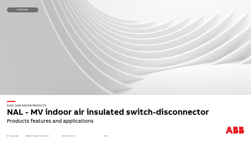
ABB 隔离开关操作步骤说明一、隔离开关各部件图例说明 1.总图说明图1①手动操作孔②合闸按钮④分闸按钮⑤当地、远动转换开关⑥加热电源开关⑦控制电源开关⑧电机电源开关③停止按钮⑨温湿度控制器⑩总电源开关2.分部说明图2①手动操作孔:摇把插入电动机构蜗杆时(面板手动操作孔内),顺时针操作为手动合闸,逆时针操作为手动分闸。
图3②合闸按钮:电动合闸时的操作按钮;③停止按钮:电动分、合闸时,需要中途停止时,切断控制电源的操作按钮;④分闸按钮:电动分闸时的操作按钮。
图4⑤当地、远动转换开关:白色标记方向打在1档处为“就地”现场人员电动操作档位;白色标记方向打在0档处为“停”现场人员手动操作档位;白色标记方向打在2档位为“远控”电调远动操作档位。
图5⑥加热电源开关:向上为“ON”(打开),向下为“OFF”(关闭);⑦控制电源开关:向上为“ON”(打开),向下为“OFF”(关闭);⑧电机电源开关:向上为“ON”(打开),向下为“OFF”(关闭);⑨温湿度控制器:显示温度、湿度,若温湿度不在环境工作温湿度下,可自动/手动操作(-5℃至20℃)加热。
图6⑩总电源开关:向左为“ON”(打开),向右为“OFF”(关闭)。
二、隔离开关操作步骤说明1.电动操作流程1.1检查总电源开关(⑩),开关状态应处于“ON”。
1.2检查加热电源开关(⑥)、控制电源开关(⑦)、电机电源开关(⑧),开关状态应处于“ON”。
1.3检查当地、远动转换开关(⑤),档位应打在1档“就地”。
1.4分、合闸操作1.4.1开关合闸:按下红色合闸按钮(②)。
1.4.2开关分闸:按下绿色合闸按钮(④)。
1.4.3分、合闸停止:在分、合闸过程中,需要中途停止时,按下黑色停止按钮(③)。
注意:电动操作完毕后,应将当地、远动转换开关(⑤),档位打在“2”“远控”电调远动操作档位。
(其它操作开关不能再进行操作,开关状态均应处于“ON”)2.手动操作流程电动分、合闸操作,开关拒动时,应进行手动分、合闸操作:2.1检查总电源开关(⑩),开关状态应处于“OFF”。
ABB--隔离开关
UL
电流等级 A
16 25 32 25 32 45
100 160 200 250 100 160 200 250
16 25 32 16 25 32 16 25 32
100 160 200 250
100
200
16 25 40 25 32 40 16 25 40 16 20 23 16 25 25
20 30 40
附件
附件概览
3/18
手柄
3/19
加长轴
3/21
辅助触头
3/22
第4极和中性极、硬连接片
3/23
端子罩、相隔板
3/24
标签板、保护插件、端子线夹、绝缘板、铜铝电缆端子线夹 3/25
正面操作的组合开关转换套件
3/27
锁紧附件
3/27
熔断器监测器、熔断器指示器(DPMM)
3/28
机械联锁套件和电气联锁、线圈
安装方式 P : 带门上安装手柄和轴
2
K : 带直接安装手柄
_ : 不带手柄和轴(无后缀)
中性极或端子宽度 N3 : 机械机构内含可拆卸的中性极 W : 宽相间距(适用于OT200-400)
操作机构位置(第一位表示在机械机构左侧的极数、第二位表示在机械机构右侧的极数) 03 : 3极(机械机构在开关左端) 04 : 4极(机械机构在开关左端) 12 : 3极(机械机构在开关极间,不适用于侧面操作) 22 : 4极(机械机构在开关极间,不适用于侧面操作)
2/78
开关类产品 目录
隔离开关熔断器组(PowerLine) - OS
产品概述 产品一览表 型号说明
3
3/1 3/5 3/6
技术数据 OS32G...OS160G OS250...OS1250 OS60...200J(UL/CSA)
写出隔离开关的操作方法

写出隔离开关的操作方法隔离开关是一种用于隔离和断开电路的设备,常用于电力系统中。
它的操作方法如下:1. 安全检查:在操作隔离开关之前,首先要进行安全检查。
确保开关周围没有可燃物或易燃物,没有电气设备漏电或短路现象,且操作人员要穿戴好个人防护装备。
2. 确定断开电路:在操作隔离开关之前,需要先确定要断开的电路。
可以查看电路图、设备标识或请专业人员提供指导。
3. 通知相关人员:在进行隔离开关操作之前,需要通知相关人员,确保其它人员不会受到电击或意外伤害。
4. 备料:准备好需要使用的隔离开关、电气工具和安全工具。
确保这些工具在操作过程中保持良好的运行状态。
5. 断开电源:断开电源是进行隔离开关操作的关键步骤。
首先,切断电源开关或拔掉电源插头。
然后,用电压表或电流表测试电源是否真正断开。
只有确认电源已经断开,才能继续操作。
6. 定位隔离开关:根据电路需求和设备位置,在合适的位置找到隔离开关。
通常,在主接线盘或配电盘上会有明显的标记。
7. 打开隔离开关:将隔离开关切换至断开位置,通常是向上移动手柄、摇把或旋转开关。
在操作过程中,要确保手指或其他部位不接触到带电部分以防触电事故发生。
8. 检查断开状态:在打开隔离开关之后,检查并确认电源已经真正断开。
可以使用电压表或电流表进行测试,确认电压为0并且没有电流流过。
9. 安全指示:在断开电源后,在隔离开关的附近设置安全指示牌或标识,提醒其他人员该电路已经断开。
10. 操作记录:在操作隔离开关时,要详细记录操作的日期、时间、操作员和操作的具体内容,以便于后续的检查和维护。
11. 恢复电源:在需要重新接通电路时,首先要确保电路和设备已经准备好,然后按照相反的步骤操作:关闭隔离开关、恢复电源,并使用合适的仪器确认电源已经重新接通。
12. 测试确认:在恢复电源后,进行测试以确认电路是否正常运行,设备是否处于预期的状态。
可以使用多功能测试仪或相关设备进行测试。
总结起来,操作隔离开关需要进行安全检查,确定断开电路,通知相关人员,备料,断开电源,定位隔离开关,打开隔离开关,检查断开状态,设置安全指示,操作记录,恢复电源,测试确认。
- 1、下载文档前请自行甄别文档内容的完整性,平台不提供额外的编辑、内容补充、找答案等附加服务。
- 2、"仅部分预览"的文档,不可在线预览部分如存在完整性等问题,可反馈申请退款(可完整预览的文档不适用该条件!)。
- 3、如文档侵犯您的权益,请联系客服反馈,我们会尽快为您处理(人工客服工作时间:9:00-18:30)。
ABB 隔离开关操作步骤说明
一、隔离开关各部件图例说明 1.总图说明
图1①手动操作孔②合闸按钮④分闸按钮⑤当地、远动转换开关⑥加热电源开关⑦控制电源开关⑧电机电源开关③停止按钮⑨温湿度控制器
⑩总电源开关
2.分部说明
图2
①手动操作孔:摇把插入电动机构蜗杆时(面板手动操作孔内),顺时针操作为手动合闸,逆时针操作为手动分闸。
图3
②合闸按钮:电动合闸时的操作按钮;③停止按钮:电动分、合闸时,需要中途停止时,切断控制电源的操作按钮;
④分闸按钮:电动分闸时的操作按钮。
图4
⑤当地、远动转换开关:白色标记方向打在1档处为“就地”现场人员电动操作档位;白色标记方向打在0档处为“停”现场人员手动操作档位;白色标记方向打在2档位为“远控”
电调远动操作档位。
图5
⑥加热电源开关:向上为“ON”(打开),向下为“OFF”(关闭);⑦控制电源开关:向上为“ON”(打开),向下为“OFF”(关闭);⑧电机电源开关:向上为“ON”(打开),向下为“OFF”(关闭);⑨温湿度控制器:显示温度、湿度,若温湿度不在环境工作温湿度下,可自动/手动操作(-5℃至20℃)加热。
图6
⑩总电源开关:向左为“ON”(打开),向右为“OFF”(关闭)。
二、隔离开关操作步骤说明
1.电动操作流程
1.1检查总电源开关(⑩),开关状态应处于“ON”。
1.2检查加热电源开关(⑥)、控制电源开关(⑦)、电机电源开关(⑧),开关状态应处于“ON”。
1.3检查当地、远动转换开关(⑤),档位应打在1档“就地”。
1.4分、合闸操作
1.4.1开关合闸:按下红色合闸按钮(②)。
1.4.2开关分闸:按下绿色合闸按钮(④)。
1.4.3分、合闸停止:在分、合闸过程中,需要中途停止时,按下黑色停止按钮(③)。
注意:电动操作完毕后,应将当地、远动转换开关(⑤),档位打在“2”“远控”电调远动操作档位。
(其它操作开关不能再进行操作,开关状态均应处于“ON”)
2.手动操作流程
电动分、合闸操作,开关拒动时,应进行手动分、合闸操作:
2.1检查总电源开关(⑩),开关状态应处于“OFF”。
2.2检查当地、远动转换开关(⑤),档位应打在0档“停”。
2.3摇把插入手动操作孔(①),顺时针操作为手动合闸,逆时针操作为手动分闸。
(开启黑色盖片,对齐手动操作孔后,方可操作)
注意:手动操作完毕后,应将手动操作孔内黑色盖片复位,将当地、远动转换开关(⑤),档位打在“2”“远控”电调远动操作档位。
并且,须将其它操作开关(⑥、⑦、⑧、⑩)打开,开关状态均应处于“ON”。
流芳供电车间:Mr Yao
2014年8月17日。