ABB S260微型断路器选型指南
ABB S2系列微型电路断路器说明书
12351020307multiple of rated current123510203018multiple of rated currentKSpace foriden t i fi c a t ion markerTripping leverTrip in d i c a t orOperatorOperatingmechanismElectro-magnetic pro t ec t ionThermal protection-bimetal Upper terminalFixed contactMoving contactLower terminalDIN rail holderArc chamberUL 1077CSA C22.2 No. 235VDE 0641IEC-898Cable protectionBDelivery ClassA - Standard item, stock to 2 weeks lead timeB - Stock to 4 weeks lead timeC - 6 to 8 week lead timeD - 10 to 12 week lead timeE - Call for deliveryCUL 1077 CSA C22.2 - NO. 235VDE 0641 IEC-898Cable & equipment protectionS261-C1NA, 1P+NDelivery ClassA - Standard item, stock to 2 weeks lead timeB - Stock to 4 weeks lead timeC - 6 to 8 week lead timeD - 10 to 12 week lead timeE - Call for deliveryDUL 1077 CSA C22.2VDE 0641 IEC-898Cable & equipment protectionS263-D63, 3 poleDelivery ClassA - Standard item, stock to 2 weeks lead timeB - Stock to 4 weeks lead timeC - 6 to 8 week lead timeD - 10 to 12 week lead timeE - Call for deliveryK UL 1077CSA C22.2 - NO. 235VDE 0641IEC-898Cable & equipment protectionDelivery ClassA - Standard item, stock to 2 weeks lead timeB - Stock to 4 weeks lead timeC - 6 to 8 week lead timeD - 10 to 12 week lead timeE - Call for delivery1 KS is for standard U.S. size.UL 1077 CSA C22.2 - NO. 235VDE 0660Cable & equipment protectionDelivery ClassA - Standard item, stock to 2 weeks lead timeB - Stock to 4 weeks lead timeC - 6 to 8 week lead timeD - 10 to 12 week lead timeE - Call for deliveryUL 1077 CSA C22.2 - NO. 235VDE 0660Cable & equipment protection➀ For use with ring tongue or cable terminals only. Cannot be used with busbar system.2 No charge when ordered with the S280(W).Delivery ClassA - Standard item, stock to 2 weeks lead timeB - Stock to 4 weeks lead timeC - 6 to 8 week lead timeD - 10 to 12 week lead timeE - Call for deliveryUL 1077 VDE 0660CSA 22.2 No. 235Cable and Equip m ent Protection Direct current applicationsThe S280UC differs from standard miniature circuit breakers in that the UC versions include a permanent magnet which aids in the extinguishing of the arc during medium and high level faults. It is necessary toobserve the correct polarity and current direction when connecting the UC breakers. Two examples of correct connection are shown below.Termination points are marked on all UC type MCBs, points one (1) and four (4) are negative and points two(2) and three (3) are positive. Four pole breakers are also available for voltage reversal applications.Delivery ClassA - Standard item, stock to 2 weeks lead timeB - Stock to 4 weeks lead timeC - 6 to 8 week lead timeD - 10 to 12 week lead timeE - Call for deliveryLow Voltage Products & Systems14.13 Z UL 1077VDE 0660CSA 22.2No. 235Fast trip characteristicS281-Z16, 1 poleS282-Z32, 2 poleS283-Z32, 3 poleDiscount schedule CB7multiple of rated current multiple of rated current14.14 Low Voltage Products & SystemsVDE 0660Cable and equipment protectionDiscount schedule CB9480 VACDelivery ClassA - Standard item, stock to 2 weeks lead timeB - Stock to 4 weeks lead timeC - 6 to 8 week lead timeD - 10 to 12 week lead timeE - Call for deliveryLow Voltage Products & Systems 14.151PhaseDiscount schedule CB8For use on load side (bottom) of S260, S270, S280 and line side (top) of S280 MCBs.Insulated busbar assembly contains 2 separate circuits for use with 1, 1+N or 2 pole MCBs.For use on load side (bottom) of S260, S270, S280 and line side (top) of S280 MCBs.Insulated busbar assembly contains 3 separate circuits for use with 1 or 3 pole MCBs.For use on load side (bottom) of S260, S270, S280 and line side (top) of S280 MCBs.Delivery ClassA - Standard item, stock to 2 weeks lead timeB - Stock to 4 weeks lead timeC - 6 to 8 week lead timeD - 10 to 12 week lead timeE - Call for deliveryInsulated busbar assembly contains 4 separate circuits for use with 3+N1 or 4 pole MCBs.For use on load side (bottom) of S260, S270, S280 and line side (top) of S280 MCBs.14.16 Low Voltage Products & SystemsPhase with 1auxiliaryDiscount schedule CB8MCBs.(bottom) of S260, S270, S280 and line side (top) of S280 MCBs.Insulated busbar assembly contains 3 separate circuits for use with 1 or 3 pole MCBs. For use on load side (bottom) of S260, S270, S280 and line side (top) of S280 MCBs.(bottom) of S260, S270, S280 and line side (top) of S280 MCBs.Delivery ClassA - Standard item, stock to 2 weeks lead timeB - Stock to 4 weeks lead timeC - 6 to 8 week lead timeD - 10 to 12 week lead timeE - Call for deliveryLow Voltage Products & Systems 14.17PhaseMCB Busbar accessoriesDiscount schedule CB8For use on line side (top) of S260 and S270 MCBs.Insulated busbar assembly contains 4 separate circuits for use with 1+N or 2 pole MCBs.For use on load side (bottom) of S260, S270, S280 and line side (top) of S280 MCBs.Delivery ClassA - Standard item, stock to 2 weeks lead timeB - Stock to 4 weeks lead timeC - 6 to 8 week lead timeD - 10 to 12 week lead timeE - Call for deliveryInsulated busbar assembly contains 1 circuit for use with 1 pole MCBs.For use on line side (top) of S260 and S270 MCBs.NOTEALL BUSBARS MAY BE CENTER FED IN OR-DER TO DOUBLE THE AMPACITY RATING14.18 Low Voltage Products & SystemsFactory mountingAll accessories can be easily mounted in the fi eld. For factory mounting of any accessory devices, add $30 list to total price per breaker. To create complete catalog number, take suf fi x of accessory device following “S2-” and add suf fi x to end of breaker part number. Multiple suf fi xes must be added in alphabetical order.Example: S272-K20A1 $ 264 (2 pole, 20A breaker with type A1 shunt trip) S272-K20 @ $96 + A1@ $138 + factory mounting @ $30 = $264 S272-K20A2H11 $ 300 (2 pole, 20A breaker with type A2 shunt trip and H11 aux. contacts) S272-K20 @ $96 + A2 @ $138 + H11 @ $36 + factory mounting @ $30 = $300Auxiliary contacts and shunt trips may be mounted in combination.Discount schedule CB8NOTE: Above accesssories are for use with types S260, S270 and S280 breakers only.Delivery ClassA - Standard item, stock to 2 weeks lead timeB - Stock to 4 weeks lead timeC - 6 to 8 week lead timeD - 10 to 12 week lead timeE - Call for deliveryLow Voltage Products & Systems 14.19SA1SA2MB-3PDMB-CLS500-ME2Discount schedule CB8Delivery ClassA - Standard item, stock to 2 weeks lead timeB - Stock to 4 weeks lead timeC - 6 to 8 week lead timeD - 10 to 12 week lead timeE - Call for delivery14.20 Low Voltage Products & SystemsDiscount schedule CB8Low Voltage Products & Systems 14.21MountingUniversal mounting position using snap-on mounting to standard 35x7.5mm DIN rail.Miniature circuit breakers (MCBs) can also be mount e d to front of door using a panel cut-out with breaker handle pro t rud i ng through panel opening for external operation. Special front mount i ng kit type ME is avail a ble (see page 2.12).ConnectionTerminals are suitable for solid or fl exible conductors from 18 to 4 AWG (0.75 to 25mm 2) with no busbar connected. When max i m um busbar size of 36 mm 2 is used, maximum cable is 6 AWG (16 mm 2).Maximum tightening torque of 17.5 in-lb (2 Nm) for line/load terminals and 4.5 in-lb (0.5Nm) for ac c es s o r y device terminals.OperationMCBs are switched on by moving the handle to the upper po s i t ion. Stamped onto the handle switch, a “I” is visible con fi rming that the breaker is closed.The MCBs are “trip-free,” if the handle is being forced to the “ON” position, the breaker will still trip under fault conditions.The “O” marking indicates that the breaker is in the “OFF” position. The MCB is now open and the load is disconnected from line power.When a breaker has tripped, the MCB handle should fi rst be set to the full “OFF” position to make certain the trip mechanism has been reset. Once the fault has been determined and cleared the MCB can again be switched “ON”.MaintenanceABB miniature circuit breakers require no specialmaintenance; only normal electrical system maintenance pro c e d ures are required.Possible mounting arrangements of MCB accessoriesAuxiliary switch/bell alarmneutral disconnect Shunt trip and/or undervoltage releaseShunt trip or undervoltage release mounted with auxiliary switch14.22 Low Voltage Products & SystemsLower terminals can be bussed together with single phase or multi-phase busbars as shown. Upper ter m i n als can also be busbar con n ect e d.Dual function terminals provided in open position for connection to busbars. Pressing on screw head opens box terminal for cable insertion. Only the lower terminal is dual func t ion.Terminals allow for con n ec t ion of cable 18-4AWG. Conductors of different sizes may also be used in same terminal.Up to fi ve conductors, 16 AWG each, can be safely connected per terminal.Lower terminal can also be bussed with solidround con d uc t or.Cables can be connected to box terminals inaddition to busbar con n ec t ions on lower, dual function terminals.Thermal tripping is independent of frequency.1 Available for purchase. See page 14.19.Infl uence of frequency on electro-magnetic tripsMagnetic trip values shown on trip curves are valid for 50/60Hz ap p li c a t ions. For frequencies other than 50/60Hz, the mag n et i c (in s tan t a n eous) trip values are increased by the factor given below:16 2/3 - 60Hz100Hz 200Hz 400Hz DC Approx. factor 1 1.1 1.2 1.5 1.5Thermal tripping is independent of frequency.S260-BS280-KS270-KLet-through values I 2tFor other curves, please contact ABB Control.Version I 2t I PeakS260B TD9980 — S260C TD9981 — S260D TD9982 —S270K TD9972 TD9950 S280K TD9978 — S280Z TD9979 — S290C TD9985 —Version Amps Time-current tripS260B 6- 63 TD9725 S270K 0.5- 8 TD9705 10- 40 TD9706 50- 63 TD9707 S280K 0.2- 8 TD9708 10- 40 TD9709 50- 63 TD9710 S280Z 0.5- 63 TD9711DescriptionAll ABB miniature circuit breakers substantially reduce the maximum let-through current from the peak avail a ble short circuit current.I K - RMS current of fault I D - Max let-through of MCB V n - System voltage V B - Arc voltage of MCB t k - Breaking time of MCBType B, C, D Type K, ZCurrent carrying capacity of type “B”, “C”, “D”, “K” and “Z” thermal trip characteristics as a function of ambient tem p er a t ure.Terminal markingsInput optional from top or bottom.Miniature circuit breaker resistance valuesAmpacities for AWG wire are based on copper cable rated 75° C, except for 16AWG which is based on 60° C wire. Taken from UL508 Table 52.2.Consult applicable standards for futher detail and information. Comparison of IEC and AWG wire sizesS280S260 & S270 S290MB-CLFront mounting clipMB-3PDRHS2-MHandle mechanismAccessories12644126461265012652Many older styles of ABB miniature circuit breakers have been replaced by new and improved versions. Many of these newer styles can be directly interchanged, both electrically and physically, with the older version. There are also many international styles of ABB circuit breakers which are not normal stock items and may be inter-changed with stocked ABB versions.Note: MCB types S260/270 and S280 can be raised to the same height as older style S210 series MCBs through the use of a height adjuster (SZ-ES68/83; $ 30 list per 20). The height adjustor snaps onto the DIN rail and raises the height of com p o n ents 68mm to match that of the S210 series (83mm).S281U-K1S281UX-K1 S282UX-K10S283UX-K2014S281UX-K25LISTED10,00010001001010.10.01Current in multiples of breaker ampere rating1.02345681014.520301.0 1.35T i m e i n s e c o n d sTime –Current trip curveThermal release threshold:1.0-1.35X Magnetic release threshold:8-14.5X Ambient calibration temperature:25°CApproval UL489 UL File No. E212323 CE Marked Voltage240 VAC 1, 2, and 3 poleCurrent ratings (A) 0.2, 0.3, 0.5, 0.75, 1, 1.6, 2, 3, 4, 5, 6, 8,10, 13, 15, 16, 20, 25, 30, 32, 40, 50, 60, 63Interrupting capacity (A) 0.2 - 25A: 14kA @ 240VAC, 1, 2, and 3 pole 30 - 63A: 10kA @ 240VAC, 1, 2, and 3 pole Frequency 50/60 HzTerminals Dual function, up to (2) stripped wires plus fork style crimp terminals.Ring tongue terminal compatible Terminal range (1) 18 - 4 AWG or (2) 18 - 8 AWG (copper wire only) or (1) 18 - 4 AWG + (1) 18 - 14 AWGSolid or stranded wire, or mixedTerminal torque 18 lb.in., combination fl at blade /No. 2 posi-drive screw Service life 20,000 operations at rated loadHACR rating Heating, Air-Conditioning, and Refrigerationrating (marked on front of breaker)Ambient temperature 25° CThermal release (A) 1.0 - 1.35 x MCB amperage rating Magnetic release8 - 14.5 x MCB amperage ratingOperational temperature -25° to +55° C rangeScale 1:1141.0526.72.1053.43.1580.12.5464.51.77451.9950.5DINRAIL3.00763.54900.6917.5S281U-K_S281UX-K_S282UX-K_S283UX-K_UL 1077 CSA C22.2VDE 0641 IEC 947-2UL 1077 CSA C22.2VDE 0641 IEC 947-2Delivery ClassA - Standard item, stock to 2 weeks lead timeB - Stock to 4 weeks lead timeC - 6 to 8 week lead timeD - 10 to 12 week lead timeE - Call for deliveryUL 1077 CSA C22.2VDE 0641 IEC 947-1S502-D13Delivery ClassA - Standard item, stock to 2 weeks lead timeB - Stock to 4 weeks lead timeC - 6 to 8 week lead timeD - 10 to 12 week lead timeE - Call for deliveryUL 1077 CSA C22.2VDE 0641 IEC-898UL 1077 CSA C22.2VDE 0660Delivery ClassA - Standard item, stock to 2 weeks lead timeB - Stock to 4 weeks lead timeC - 6 to 8 week lead timeD - 10 to 12 week lead timeE - Call for deliveryS502UC-K0.15UL 1077 CSA C22.2VDE 0660Factory mount only Delivery ClassA - Standard item, stock to 2 weeks lead timeB - Stock to 4 weeks lead timeC - 6 to 8 week lead timeD - 10 to 12 week lead timeE - Call for deliveryBusbarsS500-RD3 Handle mechanism S5001 For use on 3p/3w systems, add jumper between 4 and 8N for operation of test button.Delivery ClassA - Standard item, stock to 2 weeks lead timeB - Stock to 4 weeks lead timeC - 6 to 8 week lead timeD - 10 to 12 week lead timeE - Call for deliveryApproximate dimensionsWiring diagram。
ABB低压培训

第三章:ABB低压-框架断路器概述
1.2 ABB低压-框架断路器的特性及选型
1.2.2 选型 E2N1600 R400 PR121/P-LI FHR 3P NST
第三章:ABB低压-框架断路器概述
1.2 ABB低压-框架断路器的特性及选型
1.2.2 选型 E2N1600 R400 PR121/P-LI FHR 3P NST
第四章:ABB低压-工控产品概述
1.1 接触器
接触器分为交流操作接触器和直流操作接触器 A接触器型号示例:
A30-30-10*230-240V 50Hz/240-260V 60Hz
第四章:ABB低压-工控产品概述
1.2 继电器
ABB继电器同样分为时间继电器、中间继电器、热过载继电器等
第四章:ABB低压-工控产品概述
壳绝对安全和可靠。
第二章:ABB低压-塑壳断路器概述
1.2 ABB低压-T塑壳-灵活自由
1.2 T塑壳选型
T2N160 TMD100/1000 FF 4P 2:框架号码,可选: 1 I=160 2 I=160 3 I=250 4 I=250,320 5 I=400,630 N:分断能力
第二章:ABB低压-塑壳断路器概述
ABB软启动器分为PSR和 PST,有适宜常规起动, 也有适宜重载起动的。
型号示例: PSR16-600-70 PST 85-690-70
第四章:ABB低压-工控产品概述
1.4 按钮指示灯
ABB的按钮指示装置主要 优点是具有高防护等级和 方便快速的安装,可为客 户节约成本。该产品适用 于各种工业环境,包括户 外使用以及一些其他的应 用,如运输卡车、公共汽 车、机车车辆和公共建筑 等
1.2 继电器
断路器选型指南

断路器选型指南(低压)断路器选型:怎样才能正确选择低压断路器?以下五大步骤必不可少:(1)由线路的计算电流来决定断路器的额定电流;(2)按线路的最大短路电流来校验低压断路器的分断能力;(3)按照线路的最小短路电流来校验断路器动作的灵敏性,即线路最小短路电流应不小于断路器短路整定电流的1.3倍;(4)断路器的短路整定电流应躲过线路的正常工作启动电流;(5)按照线路上的短路冲击电流(即短路全电流最大瞬时值)来校验断路器的额定短路接通能力(最大电流预期峰值),即后者应大于前者。
读完断路器选型的五大步骤,我们再来看看断路器选型其他要注意的一些问题。
低压断路器的选用,应根据具体使用条件选择使用类别,选择额定工作电压、额定电流、脱扣器整定电流和分励、欠压脱扣器的电压电流等参数,参照产品样本提供的保护特性曲线选用保护特性,并需对短路特性和灵敏系数进行校验。
当与另外的断路器或其他保护电器之间有配合要求时,应选用选择型断路器。
1.额定工作电压和额定电流低压断路器的额定工作电压Ue。
和额定电流Ie。
应分别不低于线路,设备的正常额定工作电压和工作电流或计算电流。
断路器的额定工作电压与通断能力及使用类别有关,同一台断路器产品可以有几个额定工作电压和相对应的通断能力使用类别。
2.长延时脱扣器整定电流Ir1 所选断路器的长延时脱扣器整定电流Ir1应大于或等于线路的计算负载电流,可按计算负载电流的1~1.1倍确定;同时应不大于线路导体长期允许电流的0.8—1倍。
3.瞬时或短延时脱扣器的整定电流Ir2:所选断路器的瞬时或短延时脱扣器整定电流Ir2应大于线路尖峰电流。
配电断路器可按不低于尖峰电流1.35倍的原则确定,电动机保护电路当动作时间大于0.02s时可按不低于1.35倍起动电流的原则确定,如果动作时间小于0.02s,则应增加为不低于起动电流的1.7—2倍。
这些系数是考虑到整定误差和电动机起动电流可能变化等因素而加的。
4.短路通断能力和短时耐受能力校验低压断路器的额定短路分断能力和额定短路接通能力应不低于其安装位置上的预期短路电流。
S系列BCDK选型及尺寸ABB

L/104/69 寸附图见最后页面
4极 S204-B6 S204-B10 S204-B13 S204-B16 S204-B20 S204-B25 S204-B32 S204-B40 S204-B50 S204-B63
4极
S204-C0.5
S204-C1 S204-C2 S204-C3 S204-C4 S204-C6 S204-C10 S204-C13 S204-C16 S204-C20 S204-C25 S204-C32 S204-C40 S204-C50 S204-C63
D特性:对线路接通时有较大冲击电流的负载提供线路保护
额定电流 分段能力
S260-D
(A) (kA) 1极
1极+NA
2极
3极
3极+NA
0.5
S201-D0.5 S201NA-D0.5 S202-D0.5 S203-D0.5 S203NA-D0.5
1
S201-D1 S201NA-D1 S202-D1 S203-D1 S203NA-D1
2
S201-C2 S201NA-K2 S202-K2 S203-K2 S203NA-K2
3
S201-K3 S201NA-K3 S202-K3 S203-K3 S203NA-K3
4
S201-K4 S201NA-K4 S202-K4 S203-K4 S203NA-K4
6
S201-K6 S201NA-K6 S202-K6 S203-K6 S203NA-K6
4极
S204-D0.5
S204-D1
S204-D2 S204-D3 S204-D4 S204-D6 S204-D10 S204-D13 S204-D16 S204-D20 S204-D25 S204-D32 S204-D40 S204-D50 S204-D63
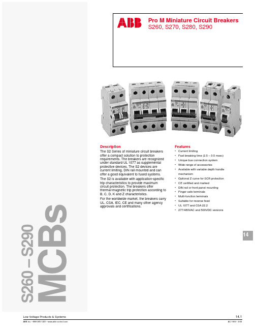
ABB S260微型断路器选型指南
S260(G)、S260(M)、S260H)
单磁式(S260(PT)、S260(M))
2.5 极数:1、2、3、4 、1+NA
脱扣特性:B、C、D、K
注意事项
1.准备好签和笔,以便记录客户所需产品的要求。
2.要把自己记录和理解的东西向客户确认一次,以免出错。
一. 名词解释
1.1额定电流:
电气设备的额定电流是指在基准环境温度下,在额定电压工作条件下,发热不超过长期发热允许温度时所允许长期通过的最大电流。
1.2分断能力:
断路器的分断能力是指该断路器安全切断故障电流的能力。
1.3脱扣器:s260系列微型断路器有电磁脱扣器与热脱扣器。
(1)电磁脱扣器:
只提供磁保护,也就是短路保护,其实际上是一个磁回力,当电流足够大时产生的磁场力克服反力弹簧吸合衔铁打击牵引杆从而带动机构动作切断电路。
说明:该脱扣状态仅是机械性的动作,只控制MCB的脱扣元件部分工作
4.4手动操作中性极:用于测量回路的中性线分断
说明:由于采用了特殊设计的手柄,可保证中性极先于断路器闭合,而后于断路器断开
4.5位置机械锁:锁定的仅为断路器操作手柄,此时如果电路发生故障,断路器自由脱扣机构仍能分断电路
4.6ABB配电附件汇流排有嵌入式汇流排(单相)与外绝缘汇流排(单相、二相、三相)。S260微型断路器的汇流排为外绝缘汇流排,
2.2S260微型断路器的系列:S260
S260OV
S260UC
S260(PT)
S260(G)
S260(M)
S260H
2.3S260微型断路器的额定电流(A):0.5、1、2、3、4、6、10、16、20、25、32、40、50、63
ABB直流断路器选型
直流产品被广泛地应用在光伏发电、电力牵引、关键电源以及港口等低压领域。ABB 全系列的直流断路器、隔离开关和熔断器以及监测和控制产品,凭借其优越的性能, 为直流配电系统提供高品质的保证。
光伏设备
随着太阳能行业的迅猛发展,大型装机容量的太阳能发电厂不断增加,大型光伏电厂 对所需的控制和保护设备的性能要求也越来越高。 当光伏电厂的功率超过某一水平时,需要采用断路器或隔离开关。特别是逆变器的保 护隔离,对低压元器件提出了更高的要求。 ABB Emax DC 直流专用空气断路器、Tmax塑壳断路器及其隔离开关系列,其优越的 性能得到全球逆变器制造商的认可,并作为他们配电的首要选择。 全新的1000V DC OT系列隔离开关是针对太阳能光伏系统中的直流分断问题而专门设 计的。在直流1000V DC时,该系列隔离开关具有出色的分断能力。 ABB 光伏专用系列产品还包括S800 PV系列,它又可分为高性能微型断路器S800 PV - S 和隔离开关S800PV-M两个系列,其额定电压最高可达1200VDC。考虑到光伏发电对 高直流电压的实际应用需求,S800PV系列产品以其高电压、防逆流、与极性无关的保 护特性和紧凑体积等特点,为客户提供了完美的光伏组件和直流汇流解决方案。
直流隔离开关和熔断器 - 隔离开关 - Emax/MS ……………………………………………………………… 13 - 隔离开关 - Tmax D ………………………………………………………………… 14 - 隔离开关 - OT / 隔离开关熔断器组 - OS ………………………………………… 15 - 熔断器式隔离开关 / 熔断器座 - E90 ……………………………………………… 17
直流电的电路保护和交流电电路保护的架构设计在信号采样、分断机构、触头材 料、形状设计等方面都有不同。这些不同决定了直流回路保护电器特定的分断能力和 快速灭弧,使得故障电路在最短时间内分断隔离。凭借着先进的制造工艺,通过对大 量的工程数据分析和经验积累,ABB在直流产品中应用了许多创新的设计,使得这些 产品在增加分断速度、减少燃弧时间、提高灭弧室效率等方面的性能大大提高。
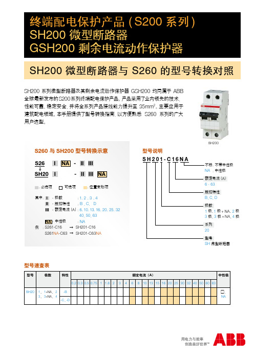
ABB 终端配电保护产品S200系列

ዐࡔู۫षళ 250011
ዐࡔࢶళู෭ 410005
ዐࡔࢶԛูࡲ 430071
ዐࡔࢋళูኣዝ 450007
ආୟ 17 ࡽ ࣀీٷေ 6 ୍ 8601
In = 50 - 63Aࣜೝ႗ࢅዐ༗ୟฆခ88୍ࡽ12B01
ׅዐళୟ 7 ࡽ ዐฆ࠽ׇႀጴ୍ 34 ୍ B3408
GS261
GS262 / 3 / 4
1+NA B、C、D
2、3、4 C、D
AC 型、A 型 0.01 0.03 0.1 0.03 0.1 0.3
AC280V(只适用于 GS261OV) 手柄+CPI
2
详见 S200 样本资料
建筑配电用 GSH200 → GS260 型号转换
3
型号速查表
型号
极数 特殊应用
70 70 35 35 35
70 70 70
ABB (ዐࡔ) ᆶ၌ࠅິ
ԛጺև : ዐࡔԛ 100015 וᄞ൶৶့ൃୟ 10 ࡽ ࢛ཚ࠽ေ ࣆۉ: (010) 8456 6688 دኈ : (010) 8456 9907
ཀৄ ິࠅݴ: ዐࡔཀৄ 300051 ࢅೝ൶ళୟ 189 ࡽ ৄࣹ࠽ׇႀጴ୍ᅃࡽӸࠅ୍ 3402 ࣆۉ: (022) 8319 1801 دኈ : (022) 8319 1802 / 1803
S260 与 SH200 型号转换示意
S26 I NA - II III
SH20 I
- II III NA
:必选项 :可选项
:位置变动项
其中: I - 极数
:1、2 、3 、4
II - 脱扣特性 :B 、C、 D
SH200-GSH200
ዐࡔఢഋ 830002
ዐࡔဇูᇱ 030002
ႎࣀٷন 66 ࡽ
ߛႎਸ݀൶ߛႎୟ
ዐୟ 86 ࡽ
ުဇন 69 ࡽ
ాࠟࡔाٷ৶ ی23 ֫
ߛႎࡔाฆခዐ႐ຕஓٷေ 16 ֫ ዐආ࠽ ׇ6 ୍ Bፗ
ဇࡔाஹᅟዐ႐ဇ୍ 10 ֫ 1009Aࡽ
ࣆۉ: (0471) 6916 330
ዐᇱဇୟ 220 ࡽ ᇧࡔٳाஹᅟዐ႐ A ፗ 1006
ࣆۉ: (0531) 8609 2726 دኈ : (0531) 8609 2724
70 ࣆۉ70 : (0731) 8268 308582 52 دኈ : (0731) 847404 575019 70
ࣆۉ: دኈ52:
型号说明
GSH201□AC□-C63/0.03□
特殊应用 不标 :无
GSH200
AP-R:抑制瞬态干扰型
(动作时间:10 - 200ms)
额定剩余电流(A)
0.01、0.03、0.1、0.3
额定电流(A)
6 - 63
脱扣特性
B、C、D
动作特性及时间
不标 :瞬动型(<100ms)
S :选择型(130 - 500ms)
防护等级 隔离指示 认证信息
上下端子可连接汇流排 U 形接线端子 IP20 手柄 CCC、RoHS、CE、CB
外形尺寸图(mm)
S260 S260-B、C、D S260NA - C、D
1、1+NA、2、3、4 B、C、D、K 0.5 - 63 A 6 kA (B、C、D) 6 kA (K) 0.75 - 25 ( ≤ 40 A) 0.75 - 35 ( 50、63 A) 上下端子可同时接导线及汇流排 U 形接线端子
- 1、下载文档前请自行甄别文档内容的完整性,平台不提供额外的编辑、内容补充、找答案等附加服务。
- 2、"仅部分预览"的文档,不可在线预览部分如存在完整性等问题,可反馈申请退款(可完整预览的文档不适用该条件!)。
- 3、如文档侵犯您的权益,请联系客服反馈,我们会尽快为您处理(人工客服工作时间:9:00-18:30)。
本文选自:工控商务网
规格 :ABB S260微型断路器选型指南
意义:为了更快更精确筛选出客户要求的产品,提高客户的满意度和交易率
事件类别:产品选型 (自动生成)
应用岗位:[业务 业务助理 技术 后勤]
需备资质:[对S260微型断路器主要技术参数了解和熟悉]
品牌:ABB系列:S260品名:微型断路器客户类型:全部行业:全部
一. 名词解释
1.1额定电流:
电气设备的额定电流是指在基准环境温度下,在额定电压工作条件下,发热不超过长期发热允许温度时所允许长期通过的最大电流。
1.2分断能力:
断路器的分断能力是指该断路器安全切断故障电流的能力。
1.3脱扣器:s260系列微型断路器有电磁脱扣器与热脱扣器。
(1)电磁脱扣器:
只提供磁保护,也就是短路保护,其实际上是一个磁回力,当电流足够大时产生的磁场力克服反力弹簧吸合衔铁打击牵引杆从而带动机构动作切断电路。
2.4S260微型断路器脱扣器形式:热磁式(S260、S260OV、S260UC
S260(G)、S260(M)、S260H)
单磁式(S260(PT)、S260(M))
2.5 极数:1、2、3、4 、1+NA
脱扣特性:B、C、D、K
注意事项
1.准备好签和笔,以便记录客户所需产品的要求。
2.要把自己记录和理解的东西向客户确认一次,以免出错。
SZ-KS 18/56N(单相)
SZ-PSB 12N(三相)
参考资料:《ABB 终端配电保护产品—辅件、附件》 2005
部分附件选型参考图表:
S260微型断路器的外形尺寸大小(mm):
五、示例
某客户需要一个S260断路器, 要求:
这一断路器要求适合于高原使用,额定电流为32A,脱扣器具有对高感性负荷和有较大冲击电流产生的配电系统的保护功能,三极。
(2)热磁脱扣器:
由于每相电流都对应安装有一个电磁脱扣装置和一个热脱扣装置,在任何一相短路或者过载时,相应的电磁脱扣装置或热脱扣装置均会动作。
1.4接线方式:两用端子可同时连接电缆和汇流排
当额定电流小于40A时,用0.75-25的导线
当额定电流为50、63A时,用0.75-35的导线
二. 了解信息
2.1S260微型断路器的选型必须向客户了解以下技术参数信息:
S2-H11
一个辅助触头2NO
S2-H20
一个辅助触头2NC
S2-H02
一个信号触头
S2-S
一个信号辅助结合触头
S2-S/H
注:NO为常开,NC为常闭
4.2分励、欠压、过压脱扣器
(1)分励脱扣器:有两种不同额定电压的类型,它们用于远程使断路器脱扣。当需远程操控时,需加分励脱扣器
说明:此辅件是利用通过控制电压来远程控制MCB的脱扣
三、选型步骤
S261无—B0.5( G)
代码
极数
型号
1
1极
2
2极
3
3极
4
4极
1NA
1+NA极
代码
0.5
1
2
3
4
6
10
16
20
25
32
40
50
63
额定电流(A)
0.5
1
2
3
4
6
10
16
20
25
32
40
50
63
参考资料:《ABB 终端配电保护产品》 2007
部分选型参考图表:
四、配件选择(只适用于S260、S260UC系列微型断路器)
4.1辅助触头(如果接触器自身所带的触点数量不能满足要求,则需要另外增加辅助触头;触头总数量为自带数量与辅助触头数量之和)
(1)辅助触点:用于指示断路器的工作状态:断开/闭合,当断路器的工作状态发生改变时,提供一个远程信号
说明:辅助触点的开闭状态取决于微型断路器的位置(ON/OFF),总是与主触点同开闭
说明:该脱扣状态仅是机械性的动作,只控制MCB的脱扣元件部分工作
4.4手动操作中性极:用于测量回路的中性线分断
说明:由于采用了特殊设计的手柄,可保证中性极先于断路器闭合,而后于断路器断开
4.5位置机械锁:锁定的仅为断路器操作手柄,此时如果电路发生故障,断路器自由脱扣机构仍能分断电路
4.6ABB配电附件汇流排有嵌入式汇流排(单相)与外绝缘汇流排(单相、二相、三相)。S260微型断路器的汇流排为外绝缘汇流排,
更多相关资料可见:工控网
4.7标签指示:ST透明标签指示内插指示内容
.SZ-KZS白色标签指示可直接书写指示或印刷内容
描述
型号
机械联动装置
S2-BPS(带信号触点)
S2-BP(不带信号触点)
手动操作中性极
S2-NT
位置机械锁
SA1(不带锁)
SA3(带锁)
标签指示
ST(透明)
SZ-KZS(空白)
SZ-KZS/5(带图示)
汇流排
选型步骤:
1.根据需要一个S260适于高原使用的断路器,所选的断路器为S260(G)系列
2.要求断路器为三极,可选其代码为3
3.要求脱口器具有对高感性负荷和有较大冲击电流产生的配电系统的保护功能,可知其脱扣特性为D,代码:D
4.额定电流为32A,确定代码为32
根据以上步骤,所选断路器的型号为S263-D32(G)
自带触点隔离
(2)欠压脱扣器:用于电压下降到额定值的70%到35%可发生脱扣,保护负载。电路电压恢复后断路器才能重新闭合,在许多情况下,它用于在安全可靠的情况下进行紧急断电
说明:此辅件采用自带延时装置,可滤过供电系统中小于100ms的干扰信号
只有电压在允许的范围的情况下欠压脱扣器允许闭合MCB
如果供应电压被中断或关闭(如紧急情况下关闭电路),欠压脱扣器即可发出脱扣信号使MCB脱扣
欠压脱扣器
S2-UA12(12DC)
S2-UA24(24AC/DC)
S2-UA48(48AC/DC)
S2-UA110(110AC/DC)
S2-UA220(220AC/DC)
S2-UA380(380AC)
过压脱扣器
S2-OV(只适用于S260)
4.3机械联动装置:此附件可在配电盘的面板开启或移动使MCB脱扣。并在相连接的线路中显示此状态。
(3)过压脱扣器:是指电压在额定电压的280+5%时发生脱扣,过压脱扣将用点设备与供电系统分开避免烧坏设备。当需要过压保护是,需加个过压脱扣器。
描述
辅件型号
分励脱扣器
S2-A1(12-60VAC/DC
40-200VA/W)
S2-A2(110-415AC
55-210VA
110-250DC
555-110W )
2.2S260微型断路器的系列:S260
S260OV
S260UC
S260(PT)SFra bibliotek60(G)S260(M)
S260H
2.3S260微型断路器的额定电流(A):0.5、1、2、3、4、6、10、16、20、25、32、40、50、63
0.5~50(S260(G)脱扣特性为C)
3、6、10(S260(PT))
(2)信号触头:可以指示由于故障原因所引起的断路器脱扣,对于人为操作断路器,信号触头不做任何指示
说明:自带红色复位手柄,它独立操作信号触点复位,无需操作断路器
自带测试按纽,可在不操作断路器情况下检查信号电路
(3)信 号,辅助结合触点:同时具有信号触点与辅助触点的功能
描述
辅件型号
一个辅助触头1NO+1NC