【ROUTE-3】CCNP ROUTE Path Control综合实验
【ROUTE-2】CCNP ROUTE OSPF综合实验
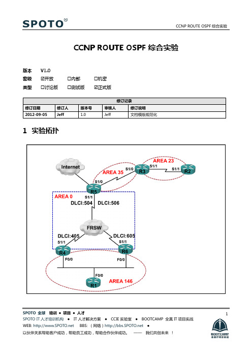
SPOTO 全球 培训 ● 项目 ● 人才 SPOTO IT 人才培训机构 ● IT 人才解决方案 ● CCIE 实验室 ● BOOTCAMP 全真IT 项目实战1CCNP ROUTE OSPF 综合实验版本 V1.0密级☑开放 ☐内部 ☐机密 类型☐讨论版 ☐测试版 ☑正式版1 实验拓扑SPOTO 全球培训●项目●人才SPOTO IT人才培训机构●IT人才解决方案●CCIE实验室●BOOTCAMP 全真IT项目实战22IP地址规划拓扑中的IP地址段采用:172.8.AB.X/24:其中AB为两台路由器编号组合,例如:R2-R3之间的AB为23,X为路由器编号,例如R3的X=3R1/R4/R6之间的网段为:172.8.146.X/24,其中X为路由器编号。
R4/R5/R6之间的网段为:172.8.100.X/24,其中X为路由器编号。
所有路由器都有一个loopback 0接口,地址格式为:X.X.X.X/32,其中X为路由器编号。
3实验需求1、要求按照下列标准配置一个OSPF网络。
2、配置一个IP网络,实验逻辑图如图,IP地址由IP地址规划部分规定而定。
3、路由协议采用OSPF,进程ID为2012 ,RID为loopback0地址。
4、模拟帧中继环境,PVC如图所示(现网中由ISP提供商提供)。
5、R4/R5/R6帧中继相连的三个站点链路OSPF网络类型配置成广播型,其中R5路由器做为永久性DR,且采用子接口方式。
6、按照图示配置OSPF区域,其中R1/R4/R6之间的区域要配置成完全末梢区域。
7、R2为新并入的站点,由于来不及布线施工而暂时并到R3这个站点上,所在区域为AREA 23,配置使得所有网络可达(采用ping测试)。
8、OSPF内部的网络希望通过R5路由器访问Internet,配置R5使其能够满足需求,只考虑内部路由器上路由的实现。
SPOTO 全球培训●项目●人才SPOTO IT人才培训机构●IT人才解决方案●CCIE实验室●BOOTCAMP 全真IT项目实战39、AREA 0基于安全的原因配置上MD5认证,密码:SPOTO10、AREA 146中,配置R1为指定路由器,R4/R6之间保持two-way的邻居关系。
CCNP中文实验手册

Gateway of last resort is not set
R2 的配置 R2(config)# key chain cisco Æ定义 chain 名称 R2(config-keychain)# key 1 Ækey 值编号,须一致 R2(config-keychain-key)# key-string aaa Æ定义密钥,须一致 R2(config)# interface s1 R2(config-if)# ip authentication mode eigrp 100 md5 Æ启用 eigrp 验证模式 md5 R2(config-if)# ip authentication key-chain eigrp 100 cisco Æ将 chain 应用到验证
步骤五:查看路由表
R1#show ip route Æ显示路由表,如下图显示证明验证通过 D 为 eigrp 路由 Codes: C - connected, S - static, I - IGRP, R - RIP, M - mobile, B - BGP
D - EIGRP, EX - EIGRP external, O - OSPF, IA - OSPF inter area N1 - OSPF NSSA external type 1, N2 - OSPF NSSA external type 2 E1 - OSPF external type 1, E2 - OSPF external type 2, E - EGP i - IS-IS, su - IS-IS summary, L1 - IS-IS level-1, L2 - IS-IS level-2 ia - IS-IS inter area, * - candidate default, U - per-user static route o - ODR, P - periodic downloaded static route
CCNP路由实验
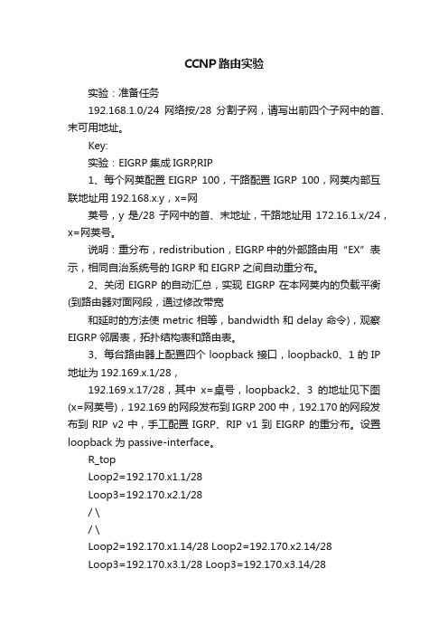
CCNP路由实验实验:准备任务192.168.1.0/24网络按/28分割子网,请写出前四个子网中的首、末可用地址。
Key:实验:EIGRP集成IGRP,RIP1、每个网荚配置EIGRP 100,干路配置IGRP 100,网荚内部互联地址用192.168.x.y,x=网荚号,y是/28子网中的首、末地址,干路地址用172.16.1.x/24,x=网荚号。
说明:重分布,redistribution,EIGRP中的外部路由用“EX”表示,相同自治系统号的IGRP 和EIGRP之间自动重分布。
2、关闭EIGRP的自动汇总,实现EIGRP在本网荚内的负载平衡(到路由器对面网段,通过修改带宽和延时的方法使metric相等,bandwidth和delay命令),观察EIGRP邻居表,拓扑结构表和路由表。
3、每台路由器上配置四个loopback接口,loopback0、1的IP 地址为192.169.x.1/28,192.169.x.17/28,其中x=桌号,loopback2、3的地址见下图(x=网荚号),192.169的网段发布到IGRP 200中,192.170的网段发布到RIP v2中,手工配置IGRP、RIP v1到EIGRP 的重分布。
设置loopback为passive-interface。
R_topLoop2=192.170.x1.1/28Loop3=192.170.x2.1/28/ \/ \Loop2=192.170.x1.14/28 Loop2=192.170.x2.14/28Loop3=192.170.x3.1/28 Loop3=192.170.x3.14/28R_left ------------- R_right说明:手工重分布在目的路由进程中进行。
redistriute 源路由进程 metric 种子度量值其它选项ping 192.170这个网段的对面路由器的loopback接口的地址,观察现象(一个通,一个不通)。
CCNP闫辉老师讲解【递归路由】实验手册(课堂笔记)
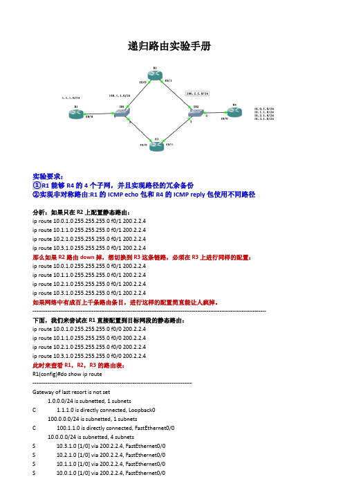
递归路由实验手册实验要求:①R1能够R4的4个子网,并且实现路径的冗余备份②实现非对称路由:R1的ICMP echo包和R4的ICMP reply包使用不同路径分析:如果只在R2上配置静态路由:ip route 10.0.1.0 255.255.255.0 f0/1 200.2.2.4ip route 10.1.1.0 255.255.255.0 f0/1 200.2.2.4ip route 10.2.1.0 255.255.255.0 f0/1 200.2.2.4ip route 10.3.1.0 255.255.255.0 f0/1 200.2.2.4那么如果R2路由down掉,想切换到R3这条链路,必须在R3上进行同样的配置:ip route 10.0.1.0 255.255.255.0 f0/1 200.2.2.4ip route 10.1.1.0 255.255.255.0 f0/1 200.2.2.4ip route 10.2.1.0 255.255.255.0 f0/1 200.2.2.4ip route 10.3.1.0 255.255.255.0 f0/1 200.2.2.4如果网络中有成百上千条路由条目,进行这样的配置简直能让人疯掉。
------------------------------------------------------------------------------------------------------------------------------ 下面,我们来尝试在R1直接配置到目标网段的静态路由:ip route 10.0.1.0 255.255.255.0 f0/0 200.2.2.4ip route 10.1.1.0 255.255.255.0 f0/0 200.2.2.4ip route 10.2.1.0 255.255.255.0 f0/0 200.2.2.4ip route 10.3.1.0 255.255.255.0 f0/0 200.2.2.4此时来查看R1,R2,R3的路由表:R1(config)#do show ip route--------------------------------------------------------------------------------------Gateway of last resort is not set1.0.0.0/24 is subnetted, 1 subnetsC 1.1.1.0 is directly connected, Loopback0100.0.0.0/24 is subnetted, 1 subnetsC 100.1.1.0 is directly connected, FastEthernet0/010.0.0.0/24 is subnetted, 4 subnetsS 10.3.1.0 [1/0] via 200.2.2.4, FastEthernet0/0S 10.2.1.0 [1/0] via 200.2.2.4, FastEthernet0/0S 10.1.1.0 [1/0] via 200.2.2.4, FastEthernet0/0S 10.0.1.0 [1/0] via 200.2.2.4, FastEthernet0/0R2(config)#do sh ip route----------------------------------------------------------------------------------------Gateway of last resort is not set100.0.0.0/24 is subnetted, 1 subnetsC 100.1.1.0 is directly connected, FastEthernet0/0C 200.2.2.0/24 is directly connected, FastEthernet0/110.0.0.0/24 is subnetted, 4 subnetsS 10.3.1.0 [1/0] via 200.2.2.4, FastEthernet0/1S 10.2.1.0 [1/0] via 200.2.2.4, FastEthernet0/1S 10.1.1.0 [1/0] via 200.2.2.4, FastEthernet0/1S 10.0.1.0 [1/0] via 200.2.2.4, FastEthernet0/1R3(config)#do show ip route-------------------------------------------------------------------------------------------Gateway of last resort is not set100.0.0.0/24 is subnetted, 1 subnetsC 100.1.1.0 is directly connected, FastEthernet0/0C 200.2.2.0/24 is directly connected, FastEthernet0/110.0.0.0/24 is subnetted, 4 subnetsS 10.3.1.0 [1/0] via 200.2.2.4, FastEthernet0/1S 10.2.1.0 [1/0] via 200.2.2.4, FastEthernet0/1S 10.1.1.0 [1/0] via 200.2.2.4, FastEthernet0/1S 10.0.1.0 [1/0] via 200.2.2.4, FastEthernet0/1可以看出R1,R2,R3都有了去往目标网络的完整路由表此时,如果ping目标网络可以通吗?当然不通,因为R1配置的静态路由只是告诉它去往4个目标网段要从f0/0接口发数据,到达R4的200.2.2.4。
OSPF实验报告-CCNP

Page 4
4
配置
R5: interface Serial1/1 no ip address encapsulation frame-relay serial restart-delay 0 ! interface Serial1/1.1 multipoint ip address 172.8.100.5 255.255.255.0 ip ospf network broadcast frame-relay map ip 172.8.100.4 504 broadcast frame-relay map ip 172.8.100.6 506 broadcast no frame-relay inverse-arp R6: interface Serial1/1 ip address 172.8.100.6 255.255.255.0 encapsulation frame-relay ip ospf network broadcast ip ospf priority 0 serial restart-delay 0 frame-relay map ip 172.8.100.5 605 broadcast no frame-relay inverse-arp 5 R4: interface Serial1/1 ip address 172.8.100.4 255.255.255.0 encapsulation frame-relay ip ospf network broadcast serial restart-delay 0 frame-relay map ip 172.8.100.5 405 broadcast no frame-relay inverse-arp
Page 18
18
ccnp交换综合实验(有图有配置) 精
实验要求:在交换机上面配置VLAN,TRUNK,VTP,STP,SPANNING TREE PORTFAST(速端口)和UPLINKFAST(上行速链路).在路由器上面配置单臂路由实现不同VLAN 之间通讯,配置双向HSRP 热备份组,实现负载均衡.配置部分:1.SW1 配置:SW1#vlan databaseSW1(vlan)#vlan 2SW1(vlan)#vlan 3SW1(vlan)#vtp serverSW1(vlan)#vtp domain sySW1(vlan)#vtp password ciscoSW1(vlan)#vtp pruningSW1(vlan)#exitSW1(config)#int rang f0/1 - 5SW1(config-if-range)#switchport mode trunkSW1(config-if-range)#exitSW1(config)#int range f0/3 - 4SW1(config-if-range)#channel-group 1 mode on // 配置以太通道SW1(config-if-range)#end2.SW2 配置:SW2#vlan databaseSW2(vlan)#vtp serverSW2(vlan)#vtp domain sySW2(vlan)#vtp password ciscoSW2(vlan)#exitSW2#conf tSW2(config)#int range f0/1 - 5SW2(config-if-range)#switchport mode trunkSW2(config-if-range)#exitSW2(config)#int range f0/3 - 4SW2(config-if-range)#channel-group 1 mode on // 配置以太通道SW2(config-if-range)#end3.SW3 配置:SW3#vlan databaseSW3(vlan)#vtp clientSW3(vlan)#vtp domain sySW3(vlan)#vtp password ciscoSW3(vlan)#exitSW3#conf tSW3(config)#int rang f0/1 -2SW3(config-if-range)#int rang f0/1 - 2SW3(config-if-range)#switchport mode trunkSW3(config-if-range)#end4.SW4 配置:SW4#vlan databaseSW4(vlan)#vtp clientSW4(vlan)#vtp domain sySW4(vlan)#vtp password ciscoSW4(vlan)#exitSW4#conf tSW4(config)#int range f0/1 - 2SW4(config-if-range)#switchport mode trunkSW4(config-if-range)#endSW4#conf tSW4(config)#spanning-tree uplinkfastSW4(config)#int f0/4SW4(config-if)#spanning-tree portfastSW4(config-if)#end5.SW3 配置:SW3#conf tSW3(config)#spanning-tree uplinkfastSW3(config)#int f0/4SW3(config-if)#spanning-tree portfastSW3(config-if)#exitSW3(config)#end6.SW2 配置:SW2#conf tSW2(config)#spanning-tree vlan 3 priority 4096 // (spanning-tree vlan 3 root primary)设置为VLAN3 的根桥SW2(config)#end7.SW1 配置:SW1#conf tSW1(config)#spanning-tree vlan 2 priority 4096 // (spanning-tree vlan 2 root primary)设置为VLAN2 的根桥SW1(config)#end8.R1 配置:R2#conf tR1(config)#int f0/0R1(config-if)#no shutdownR1(config-if)#exitR1(config)#int f0/0.1R1(config-subif)#encapsulation dot1Q 1 // HSRP 配置部分R1(config-subif)#ip address 192.168.1.254 255.255.255.0R1(config-subif)#no shutdownR1(config-subif)#exitR1(config)#int f0/0.2R1(config-subif)#encapsulation dot1q 2R1(config-subif)#ip address 192.168.2.254 255.255.255.0R1(config-subif)#no shutdownR1(config-subif)#exitR1(config-subif)#int f0/0.3R1(config-subif)#encapsulation dot1q 3R1(config-subif)#ip address 192.168.3.254 255.255.255.0R1(config-subif)#no shutdownR1(config-subif)#exitR1(config)#int f0/0.1R1(config-subif)#standby 1 ip 192.168.1.1R1(config-subif)#standby 1 priority 200 // 默认优先级为100,这里更改为200 是使其成为活跃路由器R1(config-subif)#standby 1 preempt // 配置抢占,使得本路由器从DOWN 中恢复了后仍可以抢占为活跃路由器R1(config-subif)#exitR1(config)#int f0/0.2R1(config-subif)#standby 2 ip 192.168.2.1R1(config-subif)#standby 2 priority 200R1(config-subif)#standby 2 preemptR1(config-subif)#exitR1(config)#int f0/0.3R1(config-subif)#standby 3 ip 192.168.3.19.R2 配置:R2#conf tR2(config)#int f0/0R2(config-if)#no shutdownR2(config-if)#exitR2(config)#int f0/0.2 //HSRP 配置部分R2(config-subif)#encapsulation dot1q 253 255.255.255.0R2(config-subif)#no shutdownR2(config-subif)#int f0/0.3R2(config-subif)#encapsulation dot1q 3R2(config-subif)#ip address 192.168.3.253 255.255.255.0R2(config-subif)#no shutdownR2(config-subif)#exitR2(config)#int f0/0.1R2(config-subif)#encapsulation dot1Q 1R2(config-subif)#ip address 192.168.1.253 255.255.255.0R2(config-subif)#no shutdownR2(config-subif)#endR2(config-subif)#exitR2(config)#int f0/0.1 //这一部分没有配置抢占,它将成为备用路由器R2(config-subif)#standby 1 ip 192.168.1.1R2(config-subif)#exitR2(config)#int f0/0.2R2(config-subif)#standby 2 ip 192.168.2.1R2(config-subif)#exitR2(config)#int f0/0.3R2(config-subif)#standby 3 ip 192.168.3.1R2(config-subif)#standby 3 priority 200R2(config-subif)#standby 3 preempt10.客户机配置:PC1:IP:192.168.2.2/24GW:192.168.2.1 //这里的网关地址实际上是虚拟出来的地址,真正转发数据的是活跃路由器PC3:IP:192.168.3.3/24GW:192.168.3.1实验效果验证部分:sw3#show vlan-switch briefVLAN Name Status Ports---- -------------------------------- --------- ------------------------------- 1 default active Fa0/0, Fa0/3, Fa0/5, Fa0/6Fa0/7, Fa0/8, Fa0/9, Fa0/10Fa0/11, Fa0/12, Fa0/13, Fa0/14Fa0/152 VLAN0002 active Fa0/43 VLAN0003 active1002 fddi-default active1003 token-ring-default active1004 fddinet-default active1005 trnet-default activesw3#sw3#sho vtp statusVTP Version : 2Configuration Revision : 1Maximum VLANs supported locally : 256Number of existing VLANs : 7VTP Operating Mode : ClientVTP Domain Name : syVTP Pruning Mode : EnabledVTP V2 Mode : DisabledVTP Traps Generation : DisabledMD5 digest : 0xC6 0xB6 0xCD 0xF2 0xA5 0x97 0x3C 0x7BConfiguration last modified by 0.0.0.0 at 3-1-02 00:16:27r1#show standby briefP indicates configured to preempt.|Interface Grp Prio P State Active Standby Virtual IPFa0/0.1 1 100 P Active local 192.168.1.253 192.168.1.1Fa0/0.2 2 200 P Active local 192.168.2.253 192.168.2.1Fa0/0.3 3 100 Standby 192.168.3.253 local 192.168.3.1r1#r2#sho standby briefP indicates configured to preempt.|Interface Grp Prio P State Active Standby Virtual IPFa0/0.1 1 100 Standby 192.168.1.254 local 192.168.1.1Fa0/0.2 2 100 Standby 192.168.2.254 local 192.168.2.1Fa0/0.3 3 200 P Active local 192.168.3.254 192.168.3.1r2#show standbyFastEthernet0/0.1 - Group 1State is Standby4 state changes, last state change 00:06:53Virtual IP address is 192.168.1.1Active virtual MAC address is 0000.0c07.ac01Local virtual MAC address is 0000.0c07.ac01 (v1 default)Hello time 3 sec, hold time 10 secNext hello sent in 0.716 secsPreemption disabledActive router is 192.168.1.254, priority 100 (expires in 8.364 sec) Standby router is localPriority 100 (default 100)IP redundancy name is "hsrp-Fa0/0.1-1" (default)FastEthernet0/0.2 - Group 2State is Standby4 state changes, last state change 00:06:53Virtual IP address is 192.168.2.1Active virtual MAC address is 0000.0c07.ac02Local virtual MAC address is 0000.0c07.ac02 (v1 default)Hello time 3 sec, hold time 10 secNext hello sent in 0.824 secsPreemption disabledActive router is 192.168.2.254, priority 200 (expires in 8.348 sec) Standby router is localPriority 100 (default 100)IP redundancy name is "hsrp-Fa0/0.2-2" (default)FastEthernet0/0.3 - Group 3State is Active2 state changes, last state change 00:09:31Virtual IP address is 192.168.3.1Active virtual MAC address is 0000.0c07.ac03Local virtual MAC address is 0000.0c07.ac03 (v1 default)Hello time 3 sec, hold time 10 secNext hello sent in 2.048 secsPreemption enabledActive router is localStandby router is 192.168.3.254, priority 100 (expires in 8.676 sec) Priority 200 (configured 200)IP redundancy name is "hsrp-Fa0/0.3-3" (default)r2#pc2#ping 192.168.1.1Type escape sequence to abort.Sending 5, 100-byte ICMP Echos to 192.168.1.1, timeout is 2 seconds:!!!!!Success rate is 100 percent (5/5), round-trip min/avg/max = 60/84/108 ms pc2#pc2#pc2#ping 192.168.2.1Type escape sequence to abort.Sending 5, 100-byte ICMP Echos to 192.168.2.1, timeout is 2 seconds:.!!!!Success rate is 80 percent (4/5), round-trip min/avg/max = 60/66/76 ms pc2#pc2#pc2#ping 192.168.3.1Type escape sequence to abort.Sending 5, 100-byte ICMP Echos to 192.168.3.1, timeout is 2 seconds:!!!!!Success rate is 100 percent (5/5), round-trip min/avg/max = 32/45/76 ms pc2#。
ROUTE Path Control综合实验
CCNP ROUTE Path Control综合实验一、实验拓扑:二、IP地址规划:1、拓扑中的IP地址段采用:172.8.AB.X/24:其中AB为两台路由器编号组合,例如:R3-R6之间的AB为36,X为路由器编号,例如R3的X=32、所有路由器都有一个loopback 0接口,地址格式为:X.X.X.X/24,其中X的含义同1描述。
3、各区网段为XX.XX.XX.0/24,A1网段为55.55.55.0/24和A2网段为55.55.66.0/24。
4、如无明确说明,可以按照规定范围的IP配置IP地址。
三、实验需求:所有区均用loopback 10模拟(其中A1区采用loopback 1,A2区采用loopback 2);地址写法遵守实验规则写法;如无明确说明,禁止使用静态路由,禁止出现主机路由,禁止直接使用ACL过滤数据:1 、连通:R2、R4做双向重分布,R6把RIP重分布到EIGRP,在重分布到EIGRP时metric 值一致;关闭所有自动汇总,OSPF指明RID为loopback0,要求全网ping通。
R1(config)#router ospf 100R1(config-router)#router-id 1.1.1.1R1(config-router)#network 11.11.11.0 0.0.0.255 area 1R1(config-router)#network 172.8.12.0 0.0.0.255 area 0R1(config-router)#network 172.8.14.0 0.0.0.255 area 3R2(config)#router ospf 100R2(config-router)#router-id 2.2.2.2R2(config-router)#network 172.8.12.0 0.0.0.255 area 0R2(config-router)#network 22.22.22.0 0.0.0.255 area 0R2(config-router)#redistribute rip subnetsR2(config)#router ripR2(config-router)#version 2R2(config-router)#network 172.8.23.0R2(config-router)#no auto-summaryR2(config-router)#redistribute ospf 100 metric 3R3(config)#router ripR3(config-router)#version 2R3(config-router)#network 172.8.23.0R3(config-router)#network 172.8.36.0R3(config-router)#network 33.33.33.0R3(config-router)#no auto-summaryR4(config)#router ospf 100R4(config-router)#router-id 4.4.4.4R4(config-router)#network 172.8.14.0 0.0.0.255 area 3R4(config-router)#redistribute eigrp 200 subnetsR4(config)#router eigrp 200R4(config-router)#network 44.44.44.0 0.0.0.255R4(config-router)#network 172.8.47.0 0.0.0.255R4(config-router)#no auto-summaryR4(config-router)#redistribute ospf 100 metric 10000 100 255 1 1500R5(config)#router eigrp 200R5(config-router)#network 172.8.57.0 0.0.0.255R5(config-router)#network 55.55.55.0 0.0.0.255R5(config-router)#network 55.55.66.0 0.0.0.255R5(config-router)#no auto-summaryR6(config)#router ripR6(config-router)#version 2R6(config-router)#network 172.8.36.0R6(config-router)#no auto-summaryR6(config)#router eigrp 200R6(config-router)#network 172.8.47.0 0.0.0.255R6(config-router)#network 66.66.66.0 0.0.0.255R6(config-router)#no auto-summaryR6(config-router)#redistribute rip metric 10000 100 255 1 1500R7 (config)#router eigrp 200R7(config-router)#network 172.8.47.0 0.0.0.255R7(config-router)#network 172.8.57.0 0.0.0.255R7(config-router)#network 172.8.67.0 0.0.0.255R7(config-router)#network 77.77.77.0 0.0.0.255R7(config-router)#no auto-summary2 、A1区有一http server,IP为55.55.55.100/24 ,配置使得此server只对I、II 区开放,对III区隐藏。
[福建金科]CCNP ROUTE OSPF综合实验
![[福建金科]CCNP ROUTE OSPF综合实验](https://img.taocdn.com/s3/m/3a89f493a76e58fafab003fb.png)
CCNP ROUTE OSPF综合实验一、实验目的掌握OSPF的配置命令,学会应用一些OSPF的高级功能,如虚链路,手动指定网络类型,帧中继环境中的OSPF配置,OSPF选路的修改,完全末梢区的配置,OSPF区域验证,手动汇总,默认路由的传递。
二、实验拓扑实验背景假定著名医生Dr.Stai拥有一些地方性的事务所,每个事务所专门研究牙科的某个特定领域,如牙根管填弃手术,补牙等等。
DR.Stai希望通过一个帧中继网络将他的这些事务所连接起来.这些事务所同时还希望通过共享一个公用连接实现与Internet互联,这样他们才能及时获取牙科新技术的最新发展动态.要求按照下列标准配置一个OSPF网络。
三、实验需求:1.配置一个IP网络,实验逻辑图如图,IP地址由IP地址规划而定。
2.路由协议采用OSPF,进程ID为2014,RID为loopback0地址。
3.模拟帧中继环境,PVC如图所示(现实中这由ISP提供商提供)。
4.将与帧中继相连的三个事务所配置成广播型,共子网:99.99.99.0/28,其中dental_ho(R66)事务所的路由器做为永久性DR,且采用子接口方式。
5.按照图示配置OSPF区域,其中crowns(R55),root_canals(R44),pain_center(R11)之间的区域要配置成完全末梢区域。
6.Orthopaedics(R22)是新收购的事务所,由于来不及布线施工而暂时并到surgery(R33)事务所,配置使得所有网络可达(ping测试)。
7.在dental_ho(R66)事务上配置使得所有访问internet的流量都指向网络其直连的以太网络,同时把这条路由告诉OSPF区域。
8.Area0基于安全的原因配置上MD5认证,密码:goldtech9.pain_center(R11)是事务所总部,将其做为指定路由器,与它直连的两个事务所邻居关系保持two-way状态。
10.为了减少网络流量,将pain_center(R11)所在区域汇总有主类网络通告出去。
- 1、下载文档前请自行甄别文档内容的完整性,平台不提供额外的编辑、内容补充、找答案等附加服务。
- 2、"仅部分预览"的文档,不可在线预览部分如存在完整性等问题,可反馈申请退款(可完整预览的文档不适用该条件!)。
- 3、如文档侵犯您的权益,请联系客服反馈,我们会尽快为您处理(人工客服工作时间:9:00-18:30)。
3 实验需求
1、 所有区均用 loopback 10 模拟(其中 A1 区采用 loopback 1,A2 区采用 loopback 2),地址写法 遵循 IP 地址规划中关于各区网段的规范配置;如无明确说明,禁止使用静态路由,禁止出现主机 路由,禁止直接使用 ACL 过滤数据。 2、 连通性:按照拓扑图配置 RIP/EIGRP/OSPF 路由协议,关闭所有自动汇总,要求配置 RIP 使得路 由器只向 RIP 路由器发送更新, OSPF 手动指明 RID 为 loopback0,R2、R4 做双向重分布,R6 把 RIP 重分布到 EIGRP,在重分布到 EIGRP 时 metric 值一致,要求全网 ping 通。 3、 A1 区有一 http server,IP 为 55.55.55.100/24 ,配置使得此 server 只对 I、II 区开放,对 III 区 隐藏。 4、 R4 上配置,要求 EIGRP 重分布到 OSPF 时,B 区 metric 值为 100,类型为 E1;C 区 metric 值 为 200,类型为 E1,其他路由按照默认设置。 5、 R1 有如下网段:11.11.1.0/24、11.11.2.0/24、11.11.3.0/24,要求在 R2 上配置最小路由汇总使
CCNP ROUTE Path Control 综合实验
CCNP ROUTE Path Control 综合实验
版本 密级 类型 V1.0 开放 讨论版 内部 测试版 机密 正式版
修订记录 修订日期 2012-09-05 修订人 Jeff 版本号 1.0 审核人 Jeff 修订说明 文档模版规范化
SPOTO 全球 培训 ● 项目 ● 人才 SPOTO IT 人才培训机构 ● IT 人才解决方案 ● CCIE 实验室 ● BOOTCAMP 全真 IT 项目实战 WEB: BBS: (网络) ● —— 我们共创未来 !
1 实验拓扑
SPOTO 全球 培训 ● 项目 ● 人才 SPOTO IT 人才培训机构 ● IT 人才解决方案 ● CCIE 实验室 ● BOOTCAMP 全真 IT 项目实战 WEB: BBS: (网络) ● —— 我们共创未来 !
3
以伙伴关系帮助客户成功,帮助员工成功,帮助合作伙伴成功。
1
以伙伴关系帮助客户成功,帮助员工成功,帮助合作伙伴成功。
CCNP ROUTE Path Control 综合实验
2 IP 地址规划
拓扑中的 IP 地址段采用:172.8.AB.X/24: 其中 AB 为两台路由器编号组合,例如:R3-R6 之间的 有路由器都有一个 loopback 0 接口,地址格式为:X.X.X.X/24,其中 X 为路由器编号。 各区网段为 XX.XX.XX.0/24,A1 网段为 55.55.55.0/24 和 A2 网段为 55.55.66.0/24。 如无明确说明,在不影响需求的前提下可任意设置。
2
以伙伴关系帮助客户成功,帮助员工成功,帮助合作伙伴成功。
CCNP ROUTE Path Control 综合实验
得 III 区可以访问 R1 的这三个网段。 6、 R7 上有 loopback 100 IP 为 10.10.10.1/24,配置 R5 无法接收到 10.10.10.0/24 的路由要求用 前缀列表。 7、 要求 A1 到 F 区的数据流走 R4,并将报文优先及改为 1,A2 到 G 区的数据流走 R6。 8、 假设怀疑 F 区可能发生故障, 现要求 A1 原本流向 F 区的优先级为 1 的数据流在 R1 上丢弃以免造 成拥塞。 (提示:扩展 ACL 可以定义优先级数据流) 9、 R4 上配置,要求 R4 访问 G 区走 I 区 III 区路线其他照常。(要求:不用策略路由 PBR)
SPOTO 全球 培训 ● 项目 ● 人才 SPOTO IT 人才培训机构 ● IT 人才解决方案 ● CCIE 实验室 ● BOOTCAMP 全真 IT 项目实战 WEB: BBS: (网络) ● —— 我们共创未来 !