ABB的S塑壳断路器技术样本
ABB S2系列微型电路断路器说明书
12351020307multiple of rated current123510203018multiple of rated currentKSpace foriden t i fi c a t ion markerTripping leverTrip in d i c a t orOperatorOperatingmechanismElectro-magnetic pro t ec t ionThermal protection-bimetal Upper terminalFixed contactMoving contactLower terminalDIN rail holderArc chamberUL 1077CSA C22.2 No. 235VDE 0641IEC-898Cable protectionBDelivery ClassA - Standard item, stock to 2 weeks lead timeB - Stock to 4 weeks lead timeC - 6 to 8 week lead timeD - 10 to 12 week lead timeE - Call for deliveryCUL 1077 CSA C22.2 - NO. 235VDE 0641 IEC-898Cable & equipment protectionS261-C1NA, 1P+NDelivery ClassA - Standard item, stock to 2 weeks lead timeB - Stock to 4 weeks lead timeC - 6 to 8 week lead timeD - 10 to 12 week lead timeE - Call for deliveryDUL 1077 CSA C22.2VDE 0641 IEC-898Cable & equipment protectionS263-D63, 3 poleDelivery ClassA - Standard item, stock to 2 weeks lead timeB - Stock to 4 weeks lead timeC - 6 to 8 week lead timeD - 10 to 12 week lead timeE - Call for deliveryK UL 1077CSA C22.2 - NO. 235VDE 0641IEC-898Cable & equipment protectionDelivery ClassA - Standard item, stock to 2 weeks lead timeB - Stock to 4 weeks lead timeC - 6 to 8 week lead timeD - 10 to 12 week lead timeE - Call for delivery1 KS is for standard U.S. size.UL 1077 CSA C22.2 - NO. 235VDE 0660Cable & equipment protectionDelivery ClassA - Standard item, stock to 2 weeks lead timeB - Stock to 4 weeks lead timeC - 6 to 8 week lead timeD - 10 to 12 week lead timeE - Call for deliveryUL 1077 CSA C22.2 - NO. 235VDE 0660Cable & equipment protection➀ For use with ring tongue or cable terminals only. Cannot be used with busbar system.2 No charge when ordered with the S280(W).Delivery ClassA - Standard item, stock to 2 weeks lead timeB - Stock to 4 weeks lead timeC - 6 to 8 week lead timeD - 10 to 12 week lead timeE - Call for deliveryUL 1077 VDE 0660CSA 22.2 No. 235Cable and Equip m ent Protection Direct current applicationsThe S280UC differs from standard miniature circuit breakers in that the UC versions include a permanent magnet which aids in the extinguishing of the arc during medium and high level faults. It is necessary toobserve the correct polarity and current direction when connecting the UC breakers. Two examples of correct connection are shown below.Termination points are marked on all UC type MCBs, points one (1) and four (4) are negative and points two(2) and three (3) are positive. Four pole breakers are also available for voltage reversal applications.Delivery ClassA - Standard item, stock to 2 weeks lead timeB - Stock to 4 weeks lead timeC - 6 to 8 week lead timeD - 10 to 12 week lead timeE - Call for deliveryLow Voltage Products & Systems14.13 Z UL 1077VDE 0660CSA 22.2No. 235Fast trip characteristicS281-Z16, 1 poleS282-Z32, 2 poleS283-Z32, 3 poleDiscount schedule CB7multiple of rated current multiple of rated current14.14 Low Voltage Products & SystemsVDE 0660Cable and equipment protectionDiscount schedule CB9480 VACDelivery ClassA - Standard item, stock to 2 weeks lead timeB - Stock to 4 weeks lead timeC - 6 to 8 week lead timeD - 10 to 12 week lead timeE - Call for deliveryLow Voltage Products & Systems 14.151PhaseDiscount schedule CB8For use on load side (bottom) of S260, S270, S280 and line side (top) of S280 MCBs.Insulated busbar assembly contains 2 separate circuits for use with 1, 1+N or 2 pole MCBs.For use on load side (bottom) of S260, S270, S280 and line side (top) of S280 MCBs.Insulated busbar assembly contains 3 separate circuits for use with 1 or 3 pole MCBs.For use on load side (bottom) of S260, S270, S280 and line side (top) of S280 MCBs.Delivery ClassA - Standard item, stock to 2 weeks lead timeB - Stock to 4 weeks lead timeC - 6 to 8 week lead timeD - 10 to 12 week lead timeE - Call for deliveryInsulated busbar assembly contains 4 separate circuits for use with 3+N1 or 4 pole MCBs.For use on load side (bottom) of S260, S270, S280 and line side (top) of S280 MCBs.14.16 Low Voltage Products & SystemsPhase with 1auxiliaryDiscount schedule CB8MCBs.(bottom) of S260, S270, S280 and line side (top) of S280 MCBs.Insulated busbar assembly contains 3 separate circuits for use with 1 or 3 pole MCBs. For use on load side (bottom) of S260, S270, S280 and line side (top) of S280 MCBs.(bottom) of S260, S270, S280 and line side (top) of S280 MCBs.Delivery ClassA - Standard item, stock to 2 weeks lead timeB - Stock to 4 weeks lead timeC - 6 to 8 week lead timeD - 10 to 12 week lead timeE - Call for deliveryLow Voltage Products & Systems 14.17PhaseMCB Busbar accessoriesDiscount schedule CB8For use on line side (top) of S260 and S270 MCBs.Insulated busbar assembly contains 4 separate circuits for use with 1+N or 2 pole MCBs.For use on load side (bottom) of S260, S270, S280 and line side (top) of S280 MCBs.Delivery ClassA - Standard item, stock to 2 weeks lead timeB - Stock to 4 weeks lead timeC - 6 to 8 week lead timeD - 10 to 12 week lead timeE - Call for deliveryInsulated busbar assembly contains 1 circuit for use with 1 pole MCBs.For use on line side (top) of S260 and S270 MCBs.NOTEALL BUSBARS MAY BE CENTER FED IN OR-DER TO DOUBLE THE AMPACITY RATING14.18 Low Voltage Products & SystemsFactory mountingAll accessories can be easily mounted in the fi eld. For factory mounting of any accessory devices, add $30 list to total price per breaker. To create complete catalog number, take suf fi x of accessory device following “S2-” and add suf fi x to end of breaker part number. Multiple suf fi xes must be added in alphabetical order.Example: S272-K20A1 $ 264 (2 pole, 20A breaker with type A1 shunt trip) S272-K20 @ $96 + A1@ $138 + factory mounting @ $30 = $264 S272-K20A2H11 $ 300 (2 pole, 20A breaker with type A2 shunt trip and H11 aux. contacts) S272-K20 @ $96 + A2 @ $138 + H11 @ $36 + factory mounting @ $30 = $300Auxiliary contacts and shunt trips may be mounted in combination.Discount schedule CB8NOTE: Above accesssories are for use with types S260, S270 and S280 breakers only.Delivery ClassA - Standard item, stock to 2 weeks lead timeB - Stock to 4 weeks lead timeC - 6 to 8 week lead timeD - 10 to 12 week lead timeE - Call for deliveryLow Voltage Products & Systems 14.19SA1SA2MB-3PDMB-CLS500-ME2Discount schedule CB8Delivery ClassA - Standard item, stock to 2 weeks lead timeB - Stock to 4 weeks lead timeC - 6 to 8 week lead timeD - 10 to 12 week lead timeE - Call for delivery14.20 Low Voltage Products & SystemsDiscount schedule CB8Low Voltage Products & Systems 14.21MountingUniversal mounting position using snap-on mounting to standard 35x7.5mm DIN rail.Miniature circuit breakers (MCBs) can also be mount e d to front of door using a panel cut-out with breaker handle pro t rud i ng through panel opening for external operation. Special front mount i ng kit type ME is avail a ble (see page 2.12).ConnectionTerminals are suitable for solid or fl exible conductors from 18 to 4 AWG (0.75 to 25mm 2) with no busbar connected. When max i m um busbar size of 36 mm 2 is used, maximum cable is 6 AWG (16 mm 2).Maximum tightening torque of 17.5 in-lb (2 Nm) for line/load terminals and 4.5 in-lb (0.5Nm) for ac c es s o r y device terminals.OperationMCBs are switched on by moving the handle to the upper po s i t ion. Stamped onto the handle switch, a “I” is visible con fi rming that the breaker is closed.The MCBs are “trip-free,” if the handle is being forced to the “ON” position, the breaker will still trip under fault conditions.The “O” marking indicates that the breaker is in the “OFF” position. The MCB is now open and the load is disconnected from line power.When a breaker has tripped, the MCB handle should fi rst be set to the full “OFF” position to make certain the trip mechanism has been reset. Once the fault has been determined and cleared the MCB can again be switched “ON”.MaintenanceABB miniature circuit breakers require no specialmaintenance; only normal electrical system maintenance pro c e d ures are required.Possible mounting arrangements of MCB accessoriesAuxiliary switch/bell alarmneutral disconnect Shunt trip and/or undervoltage releaseShunt trip or undervoltage release mounted with auxiliary switch14.22 Low Voltage Products & SystemsLower terminals can be bussed together with single phase or multi-phase busbars as shown. Upper ter m i n als can also be busbar con n ect e d.Dual function terminals provided in open position for connection to busbars. Pressing on screw head opens box terminal for cable insertion. Only the lower terminal is dual func t ion.Terminals allow for con n ec t ion of cable 18-4AWG. Conductors of different sizes may also be used in same terminal.Up to fi ve conductors, 16 AWG each, can be safely connected per terminal.Lower terminal can also be bussed with solidround con d uc t or.Cables can be connected to box terminals inaddition to busbar con n ec t ions on lower, dual function terminals.Thermal tripping is independent of frequency.1 Available for purchase. See page 14.19.Infl uence of frequency on electro-magnetic tripsMagnetic trip values shown on trip curves are valid for 50/60Hz ap p li c a t ions. For frequencies other than 50/60Hz, the mag n et i c (in s tan t a n eous) trip values are increased by the factor given below:16 2/3 - 60Hz100Hz 200Hz 400Hz DC Approx. factor 1 1.1 1.2 1.5 1.5Thermal tripping is independent of frequency.S260-BS280-KS270-KLet-through values I 2tFor other curves, please contact ABB Control.Version I 2t I PeakS260B TD9980 — S260C TD9981 — S260D TD9982 —S270K TD9972 TD9950 S280K TD9978 — S280Z TD9979 — S290C TD9985 —Version Amps Time-current tripS260B 6- 63 TD9725 S270K 0.5- 8 TD9705 10- 40 TD9706 50- 63 TD9707 S280K 0.2- 8 TD9708 10- 40 TD9709 50- 63 TD9710 S280Z 0.5- 63 TD9711DescriptionAll ABB miniature circuit breakers substantially reduce the maximum let-through current from the peak avail a ble short circuit current.I K - RMS current of fault I D - Max let-through of MCB V n - System voltage V B - Arc voltage of MCB t k - Breaking time of MCBType B, C, D Type K, ZCurrent carrying capacity of type “B”, “C”, “D”, “K” and “Z” thermal trip characteristics as a function of ambient tem p er a t ure.Terminal markingsInput optional from top or bottom.Miniature circuit breaker resistance valuesAmpacities for AWG wire are based on copper cable rated 75° C, except for 16AWG which is based on 60° C wire. Taken from UL508 Table 52.2.Consult applicable standards for futher detail and information. Comparison of IEC and AWG wire sizesS280S260 & S270 S290MB-CLFront mounting clipMB-3PDRHS2-MHandle mechanismAccessories12644126461265012652Many older styles of ABB miniature circuit breakers have been replaced by new and improved versions. Many of these newer styles can be directly interchanged, both electrically and physically, with the older version. There are also many international styles of ABB circuit breakers which are not normal stock items and may be inter-changed with stocked ABB versions.Note: MCB types S260/270 and S280 can be raised to the same height as older style S210 series MCBs through the use of a height adjuster (SZ-ES68/83; $ 30 list per 20). The height adjustor snaps onto the DIN rail and raises the height of com p o n ents 68mm to match that of the S210 series (83mm).S281U-K1S281UX-K1 S282UX-K10S283UX-K2014S281UX-K25LISTED10,00010001001010.10.01Current in multiples of breaker ampere rating1.02345681014.520301.0 1.35T i m e i n s e c o n d sTime –Current trip curveThermal release threshold:1.0-1.35X Magnetic release threshold:8-14.5X Ambient calibration temperature:25°CApproval UL489 UL File No. E212323 CE Marked Voltage240 VAC 1, 2, and 3 poleCurrent ratings (A) 0.2, 0.3, 0.5, 0.75, 1, 1.6, 2, 3, 4, 5, 6, 8,10, 13, 15, 16, 20, 25, 30, 32, 40, 50, 60, 63Interrupting capacity (A) 0.2 - 25A: 14kA @ 240VAC, 1, 2, and 3 pole 30 - 63A: 10kA @ 240VAC, 1, 2, and 3 pole Frequency 50/60 HzTerminals Dual function, up to (2) stripped wires plus fork style crimp terminals.Ring tongue terminal compatible Terminal range (1) 18 - 4 AWG or (2) 18 - 8 AWG (copper wire only) or (1) 18 - 4 AWG + (1) 18 - 14 AWGSolid or stranded wire, or mixedTerminal torque 18 lb.in., combination fl at blade /No. 2 posi-drive screw Service life 20,000 operations at rated loadHACR rating Heating, Air-Conditioning, and Refrigerationrating (marked on front of breaker)Ambient temperature 25° CThermal release (A) 1.0 - 1.35 x MCB amperage rating Magnetic release8 - 14.5 x MCB amperage ratingOperational temperature -25° to +55° C rangeScale 1:1141.0526.72.1053.43.1580.12.5464.51.77451.9950.5DINRAIL3.00763.54900.6917.5S281U-K_S281UX-K_S282UX-K_S283UX-K_UL 1077 CSA C22.2VDE 0641 IEC 947-2UL 1077 CSA C22.2VDE 0641 IEC 947-2Delivery ClassA - Standard item, stock to 2 weeks lead timeB - Stock to 4 weeks lead timeC - 6 to 8 week lead timeD - 10 to 12 week lead timeE - Call for deliveryUL 1077 CSA C22.2VDE 0641 IEC 947-1S502-D13Delivery ClassA - Standard item, stock to 2 weeks lead timeB - Stock to 4 weeks lead timeC - 6 to 8 week lead timeD - 10 to 12 week lead timeE - Call for deliveryUL 1077 CSA C22.2VDE 0641 IEC-898UL 1077 CSA C22.2VDE 0660Delivery ClassA - Standard item, stock to 2 weeks lead timeB - Stock to 4 weeks lead timeC - 6 to 8 week lead timeD - 10 to 12 week lead timeE - Call for deliveryS502UC-K0.15UL 1077 CSA C22.2VDE 0660Factory mount only Delivery ClassA - Standard item, stock to 2 weeks lead timeB - Stock to 4 weeks lead timeC - 6 to 8 week lead timeD - 10 to 12 week lead timeE - Call for deliveryBusbarsS500-RD3 Handle mechanism S5001 For use on 3p/3w systems, add jumper between 4 and 8N for operation of test button.Delivery ClassA - Standard item, stock to 2 weeks lead timeB - Stock to 4 weeks lead timeC - 6 to 8 week lead timeD - 10 to 12 week lead timeE - Call for deliveryApproximate dimensionsWiring diagram。
ABB塑壳断路器样本_Simax 明扬工控网 工控产品在线直销商城
安装位置
Simax 断路器可以多种方式安装在开关柜里 :水平、 垂直或平装在安装板上,且不会影响其额定参数。由于 Simax 断路器可以采用上进线或下进线的接线方式。可从 上端或下端接入电源,因此其安装相当简单,且不会影 响断路器性能。
符合标准
Simax 断路器及其附件均符合 IEC 60947-2 标准和 GB14048.2标准。
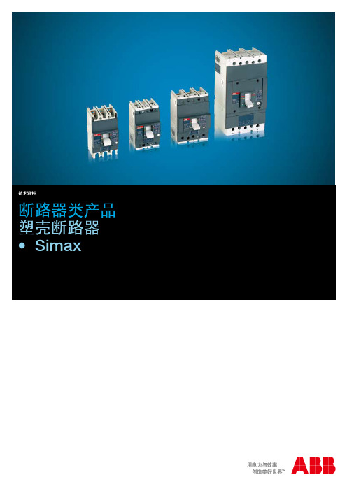
Simax
Simax 塑壳断路器
产品特性一览表
产品特性
Sim 100
额定不间断电流 Iu 极数 额定工作电压 Ue 额定冲击耐受电压 Uimp 额定绝缘电压 Ui 工频测试电压 1 分钟 额定极限短路分断能力 Icu (AC) 50 - 60 Hz 380/415 V (AC) 50 - 60 Hz 500 V (DC) 250 V - 2 极串联 (DC) 500 V - 3 极串联 额定运行短路分断能力 Ics (AC) 50 - 60 Hz 380 / 415 V (AC) 50 - 60 Hz 500 V 使用类别 (IEC 60947-2 GB14048.2) 符合标准 (IEC 60947-2 GB14048.2) 隔离功能 [%lcu] [%lcu] 50% [kA] [kA] [kA] [kA] (AC) 50-60 Hz [A] [p] [V] [kV] [V] [V] A 10 3 3 B 16 5 5 6 690 100
技术资料
断路器类产品 塑壳断路器 ● Simax
富士变频器、富士接触器、富士开关按钮、富士温控表、富士断路器、富士触摸屏、富士P L C 三菱变频器、三菱接触器、和泉开关按钮、RKC温控表、三菱断路器、三菱触摸屏、三菱P L C 西门子变频器、西门子接触器、西门子开关按钮、西门子P L C、西门子断路器、西门子触摸屏 ABB变频器、ABB接触器、ABB开关按钮、ABB断路器、AUT ONI CS 光电开关、欧姆龙光电 海利普变频器、丹佛斯变频器、日立变频器、东芝变频器、三肯变频器、三晶变频器、 L G变频器、L G接触器、天得开关按钮、天得限位开关、L G断路器、L GP L C 施耐德变频器、施耐德接触器、施耐德开关按钮、施耐德断路器、施耐德P L C 士林变频器、士林接触器、康沃变频器、AUT ONI CS 温控表、台安断路器、AUT ONI CS 行程开关
ABB断路器产品样本
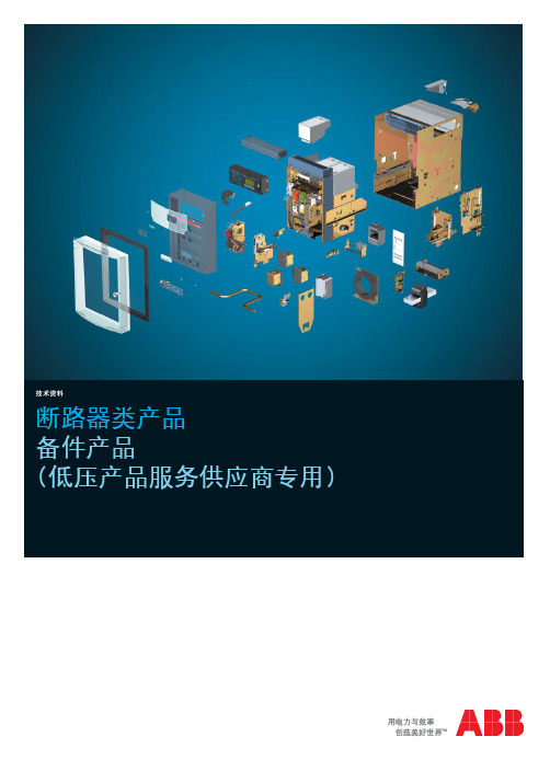
技术资料断路器类产品备件产品(低压产品服务供应商专用)缺图储备空气断路器和塑壳断路器的备件是对电气系统进行正确维护的必要条件。
尤其对于那些建立于多年前,且有部分所用低压元器件正被逐渐淘汰的电气系统,更显重要。
ABB低压产品业务部备件库存可为客户提供长期的供货保证。
从80年代迄今生产的所有断路器,ABB均做了足够的备件库存,并为您提供有效的备件服务。
ABB低压产品业务部是唯一可提供有质量保证的原装备件供应商,可按客户所需,提供整套备件方案。
并可在本地灵活安排备件供应。
为确保给客户提供最大限度的支持,简化备件的选型和订购,ABB低压产品业务部还构建了密集的服务供应商网络,其专业的服务人员可直接为您解答各种产品问题,并快速处理各种需求。
本样本能帮助简化备件的选型和订货。
此外,备件的型号和参数以标签形式贴在断路器上,查找方便快捷。
ABB低压产品业务部 - 技术服务技术技能 掌控于心备件产品 一应俱全目录 页2E m a x E3I s o m a x S4T m a x T1M e g a m a x F1/1断路器备件产品1M e g a m a xF空气断路器 - Megamax FMegamax F1 / F2产品结构端子夹头电流互感器与电子脱扣器的连线 (AR1)电流互感器与电子脱扣器的连线 (PR1)电子脱扣器的脱扣线圈(YO1)1/2断路器备件产品1M e g a m a x F空气断路器 - Megamax F订货资料Megamax F1 / F21/3断路器备件产品1M e g a m a x F空气断路器 - Megamax F订货资料Megamax F1 / F21/4断路器备件产品1M e g a m a x F空气断路器 - Megamax F产品结构Megamax F4 / F5 / F6端子夹头电流互感器与电子脱扣器的连线 (AR1)电流互感器与电子脱扣器的连线 (PR1)电子脱扣器的脱扣线圈(YO1)前档1/5断路器备件产品1M e g a m a x F空气断路器 - Megamax F订货资料Megamax F4 / F5 / F61/6断路器备件产品1M e g a m a x FMegamax F4 / F5 / F6空气断路器 - Megamax F订货资料1/7断路器备件产品1M e g a m a x F空气断路器 - Megamax F订货资料Megamax F4 / F5 / F62/1断路器备件产品2E m a xE220177空气断路器 - Emax E产品结构连线灭弧罩抽出部分的二次插件接地插组件提升板2/2断路器备件产品2E m a xE空气断路器 - Emax E订货资料Emax E1 / E63/1断路器备件产品3I s o m a xS空气断路器 - Isomax S 系列产品结构注: 如需订购相关备件,请与ABB 低压产品业务部联系剩余电流底座接4/14T m a x T断路器备件产品T1T2T3T4T5T6空气断路器 - Tmax T产品结构注: 如需订购相关备件,请与ABB 低压产品业务部联系备检维升支培长久的保证:库存备件齐全,涵盖了 ABB 在中国所销售的各类通过对断路器进行全面检修,可恢复断路器电气及机械部件的性提供整套的预防性和维护方案,提高系统的可靠性和安全性,并借助转换套件,采用新型断路器替换原有的旧断路器。
ABB塑壳断路器的功能及作用

ABB 设计的2种系列的塑壳断路器:众所周知的Isomax S系列和新开发的Tmax系列(在2003国际设计中,以其技术含量和环保而闻名)。
此外,Tmax 更具有极高的性能水平:外形尺寸小,安装简单。
再加上双重绝缘,确保操作者安全。
因其Tmax 断路器的卓越性能以及脱扣器和附件的完整性,可使用在交流和直流用电工厂的主配电和子配电中。
Tmax 特性 Tmax系列技术高,采用了最先进的设计和模拟工具,保证在最小的外形尺寸上达到最优的性能。
由于灭弧室采用最新科技和能够加快分闸速度,Tmax系列断路器可极大地限制允通能量、减少电流峰值,从而避免装置过热和降低电动应力。
此外,Tmax系列断路器使用了一套完全通用和标准的附件,具有很多优点:减少库存、方便灵活和使用方便。
它们皆可选配(使用电流高达500A的)新型剩余电流脱扣器。
(RC221, RC222, RC223)应用领域
塑壳断路器应用在工业和城市低压工厂,工作电流从1 - 1000A。
它们安装在直流和交流配电柜中,用于电机保护(电机控制中心)、发电机保护、电容器保护和终端用户。
艾驰商城是国内最专业的MRO工业品网购平台,正品现货、优势价格、迅捷配送,是一站式采购的工业品商城!具有 10年工业用品电子商务领域研究,以强大的信息通道建设的优势,以及依托线下贸易交易市场在工业用品行业上游供应链的整合能力,为广大的用户提供了传感器、图尔克传感器、变频器、断路器、继电器、PLC、工控机、仪器仪表、气缸、五金工具、伺服电机、劳保用品等一系列自动化的工控产品。
如需进一步了解相关断路器产品的选型,报价,采购,参数,图片,批发等信息,请关注艾驰商城。
ABB塑壳断路器样本

Sim 100, 160, 250
plo=
!
Sim 500
!"# AC [VA] 24V AC / DC 110…120V AC - 110…125V DC 220…240V AC - 220…250V DC 380…400V AC !"ãë Sim 500 100 100 100 100 < _ 15 DC [W] 120 120 120 < _ 15
Sim 160
Sim 250
Sim 500
!"
[W /
In[A] 10 15 16 20 25 30 32 40 50 60 63 75 80 90 100 125 160 200 250 320 400 500 6 7 7 10.7 15 5.6 7.9 7.9 13.2 17.8 60 65 102 4.2 4.8 4.8 2.6 3.7 3.9 4.3 4.3 1.8 2 2.1 2.1 2.6 3.7
J= J= J= J= J= J= J= J= J=
!"=J=plo ! " # =J=rso ! " # $ % =J=^ru !"#$ ! " # $ % =J=oea=L=oeb ! " # =J=mii ! " # $ % & =J=cia ! =J=m_ !
!"#$%&
=K KKKKKKKKKKKKKKKKKKKKKKKKKKKKKKKKKKKKKKKKKKKKKKKKKKKKKKKKKKKKKKKKKKKKKKKKKKKKKKKK V=J=NM
!K KKKKKKKKKKKKKKKKKKKKKKKKKKKKKKKKKKKKKKKKKKKKKKKKKKKKKKKKKKKKKKKKKKKKKKKKKKKKKKKKKKKKKKKKKKKKKKKKKKKKKKKKKKKKKKKKK NO
ABB塑壳断路器

塑料外壳式断路器作为低压配电系统和电动机保护回路中的过载、短路保护电器,额定电流在600A以下,且短路电流不大时,可选用塑壳断路器;因而塑壳断路器是应用广泛的产品。
塑壳断路器工作原理联锁装置有机械联锁和电气联锁两种类型。
工作原理是:(1)机械联锁装置一般使用钢丝绳或者杠杆机构,以机械位置的变动(也可采用多功能程序锁)来保证在断路器切断电源以前,隔离开关的操作把手不能动作。
(2)电气联锁装置电气联锁一般有两种联锁方式,一种是通过操作机构上的联动辅助接点(常开或常闭)去控制隔离开关的把手。
当断路器未断开时,隔离开关操作把手不能动作。
另一种电气联锁是利用距离开关操作机构上的联动辅助接点(常开或常闭)去控制断路器。
当拉动隔离开关的把手时,联动辅助接点(常开或常闭)使断路器动作以切断电路,从而可防止带负荷拉动距离开关的事故。
塑壳断路器的特性1.额定极限短路分断能力Icu:断路器的分断能力指标有两种:额定极限短路分断能力Icu和额定运行短路分断能力Ics。
Ics作为一个特性参数,并非只简单考虑断路器的分断能力,而是作为一种分断指标,即分断几次短路故障后,还能保证其正常工作。
2.限流分断能力:断路器发生短路时、触头快速打开产生电弧,相当于在线路中串入1个迅速增加的电弧电阻,从而限制了故障电流的增加。
断路器断开时间越少,Ics就越接近Icu,限流效果就越好,也可大大降低短路电流引起的电磁效应、电动效应和热效应对断路器和用电设备的不良影响,延长断路器的使用寿命。
3.短路保护:短路保护就是短路瞬时跳闸。
要注意在负荷变化后及时调整保护的整定值,防止整定值过小频繁跳闸影响供电质量,或整定值过大使线路和设备得不到有效保护。
4.过载延时保护:过载延时保护是指负荷电流超过设备的限定范围有烧毁设备的危险,保护装置能在一定时间内切断电源。
过载有个热量积累的过程,保护动作不需要过于迅速。
对于短时过电流,保护不应该动作。
5.隔离功能:隔离功能就是要求断路器断开后的泄漏电流不致对人身和设备产生危害。
ABB断路器参数调试讲义(完整资料).doc

【最新整理,下载后即可编辑】ABB 断路器参数调试讲义电控柜的断路器进行设置,在ABB 塑壳断路器(正面)下方有两个旋钮(见下图),通过调节旋钮的位置可以设置断路器的过流、过载保护值,具体设置方法如下:一、ABB 塑壳断路器过流、过载旋钮设置说明:1、过流调节旋钮,设置电控箱整个负载的过流保护值,调节范围从2000A —4000A ,从MIN —MED —MAX 共有9个档位,档位对应值如下:MIN (1)档—2000A; (2)档—2250A; (3)档—2500A; (4)档—2750A;MED (5)档—3000A; (6)档—3250A; (7)档—3500A; (8)档—3750A ;MAX (9)档—4000A;2、过载调节旋钮,设置电控箱整个负载的过载保护值,调节范过流调节旋钮过载调节旋钮围从280A—400A,从MIN—MED—MAX共有9个档位,档位对应值如下:MIN(1)档—280A; (2)档—295A; (3)档—310A; (4)档—325A;MED(5)档—340A; (6)档—355A; (7)档—370A; (8)档—385A;MAX(9)档—400A;二、ABB断路器机型设置说明3.1、空气断路器的框架电流Iu、额定电流Ie、额定电流整定值Ir的含义是什么?•框架电流Iu:又称为额定不间断电流。
指在规定条件下,电器在长期工作制下,各部件的温升不超过规定极限值时所承受的电流值。
•额定工作电流Ie:指在规定条件下,能保证电器正常工作的电流值。
它和额定电压、电网频率、额定工作制、使用类别、触头寿命及防护等级等因素有关。
有时被标识为In。
•额定电流整定值Ir:这是使用者通过断路器的脱扣器自行整定的一个电流值,断路器根据使用者整定的Ir对电路进行过载、短路保护。
•比如ABB的塑壳断路器S5N400 R320 PR112/LI FF 3P , Iu=400A Ie=320A, Ir=( 0.4 – 1)Ie 可调。
ABB样本资料
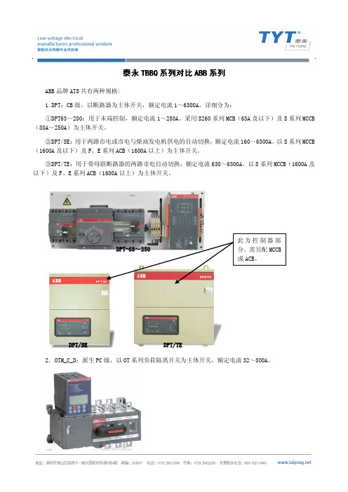
泰永TBBQ系列对比ABB系列ABB品牌ATS共有两种规格:1.DPT:CB级,以断路器为主体开关,额定电流1~6300A。
详细分为:①DPT63~250:用于末端控制,额定电流1~250A。
采用S260系列MCB(63A及以下)及S系列MCCB (80A~250A)为主体开关。
②DPT/SE:用于两路市电或市电与柴油发电机供电的自动切换,额定电流160~6300A。
以S系列MCCB (1600A及以下)及F、E系列ACB(1600A以上)为主体开关。
③DPT/TE:用于带母联断路器的两路市电自动切换,额定电流630~6300A。
以S系列MCCB(1600A及以下)及F、E系列ACB(1600A以上)为主体开关。
2.OTM_C_D:派生PC级,以OT系列负荷隔离开关为主体开关,额定电流32~800A。
DPT/SE DPT/TE泰永科技TBBQ3系列自动转换开关电器是完全按照GB/T14048.11标准要求专门设计的PC级一体化ATSE,其特点如下:●驱动力采用励磁驱动。
励磁驱动是最简单的电动力源,比其它采用减速电机作为驱动力的结构(CB 级、采用隔离/负荷开关的ATSE)可靠性要高。
●采用连杆传动、结构自锁,整个传动机构十分简单(运动部件不超过10个)。
●触头材料均采用银合金,大大提高导电性能。
●触头压力大,可有效防止触头的跳动并承受较高的电流冲击。
●分离速度快(100A以下能够达到0.75m/s以上的速度),有利于灭弧。
●有专门的灭弧装置,快速灭弧。
●驱动机构非常可靠,可以做到大电流等级(泰永科技TBBQ3系列,一种驱动机构可以做到5000A,而且可靠性很高)。
针对PC级产品泰永TBBQ3系列与ABB OTM_C_D系列产品对比如下:一、产品类别不同泰永TBBQ3系列:三段式、两段式、轨道型、瞬间并联型、抽出带旁路型、交直流混合型。
OTM_C_D系列:三段式。
备注:泰永TBBQ3系列种类齐全,可为多行业提供针对性更强的解决方案。