CY-2010A数字风速仪说明书
sY_2010A说明书
sY_2010A说明书
sY_2010A主界面显示以下信息:
风扇、加热、排潮以及喷蒸的自动/手动状态,和各自当前的开关(正反转)状态。
6点含水率测量值,以及含水率均值。
含水率月标值。
干球温度值、目标值:湿球温度值、目标值:升温速度和当前干球温度目标值。
注:“←”号代表风扇正转:“→”号代表风扇反转:“△”号代表阀门开:“”代表阀门关。
在主界面下可以完成以下操作:
风扇的手动/白动控制:按“风扇”键,风扇状念兰处于选中状念(黑底白字显示)。
如果风扇此时为反转,则按“川正”键后风扇进入手动状态并停止:按“关/及”键无影响:按“白动”键后风扇进入自动状态。
如果风扇此时为停止:,则按“开正”键后风扇进入于动状态并开始正转:按“关/反”键后风扇进入手动状态并开始反转:按“自动”键后风扇进入自动状态。
如果风扇此时为正转,其动作变化与反转状态下类同。
Met One 010C 风速传感器用户手册说明书

MODEL010CWIND SPEED SENSOROPERATION MANUALMet One Instruments, IncCorporate Sales & Service: 1600 NW Washington Blvd. Grants Pass, OR 97526 Tel (541) 471-7111 Fax (541) 471-7116******************1.0 GENERAL INFORMATION1.1 The 010C Wind Speed Sensor uses a durable, three-cup anemometer assembly andsolid-optical link with a 40-slot chopper disk to produce a pulsed output whosefrequency is proportional to wind speed. An internal heater reduces moisture forextended bearing life. This sensor is usually used in conjunction with the 191 Cross arm Assembly. The sensor may be used with a translator module, or used directlywith a variety of data loggers.1.2 The Sensor Cable has a quick-connect connector with vinyl jacketed, shielded cable.Cable length is given in -XX feet on each cable part number. A 1953-XX cable isused with translators having terminal strip connections.Table 1-1Model 010C Wind Speed Sensor SpecificationsPerformance CharacteristicsMaximum Operating Range 0-60 meters/sec or 0-125 mphStarting Speed 0.27 meters/sec or 0.6 mphCalibrated Range 0-50 meters/sec or 0-100 mphAccuracy ±1% or 0.15 mphTemperature Range -50︒C to +85︒CResponse Distance constant less than 5 ft of flow**The distance traveled by the air after a sharp-edged gust has occurred for theanemometer rate to reach 63% of the new speed. Distant constant less than 15ft of flow with optional 010C-1 aluminum cupset.Electrical CharacteristicsPower Requirements 12 VDC at 10 mAOutput Signal 11-volt pulseOutput Impedance 100 ohms maximumHeater Power Requirement 12 VDC at 350 mAStandard Cable Length 300’ maximum (consult factory if longercable is to be used for special requirements) Physical CharacteristicsWeight 1.1 poundsFinish Anodized aluminumMounting Use with 191 CrossarmCabling 1953-XX Cable (XX is cable length in feet)Optional AccessoriesA. External heater and power supply for extreme low temperature operation.B. Ice Skirt for extreme icing environments.C. Aluminum cup assembly.2.0 INSTALLATION2.1 The 010C Wind Speed InstallationA. Mount the cup assembly and secure with the Allen head set screw, check to seethat the cup assembly rotates freely.B. Install the sensor in the end of the Model 191 Crossarm Assembly (the endwithout the bushing).C. Tighten the locking set screw. Do not over-tighten. Apply a small amount ofsilicone grease to set screws to prevent freezing in adverse environments.D. Connect the cable assembly to the keyed sensor receptacle and tape it to themounting arm.2.2 WiringA. The cable assembly contains five wires. Typical wiring hookup is shown inFigure 2-1.No Connection White/Brown ShieldElectrical ConnectorView looking at connector pins. (Pins are also identified on connector).2.3 Lightning ProtectionA. Weather sensors are sensitive to direct or nearby lightning strikes. A well-grounded metal rod or frame should be placed above the sensor installation. Inaddition, the shield on the signal cable leading to the translator must beconnected to a good earth ground at the translator end and the cable routeshould not be vulnerable to lightning.3.0 OPERATIONAL CHECK-OUT AND CALIBRATION3.1 010C Wind Speed Sensor Check-OutA. Spinning the anemometer cup assembly will produce a series of pulses (40pulses per revolution). To verify sensor output, monitor this signal with either thetranslator module, data logger, or an oscilloscope. (Refer to Frequency vs. WindSpeed Table 3-1). Spinning the hub of the wind speed transmitter without thecup assembly mounted and allowing it to coast to a stop will give a goodindication of threshold performance; a jerky or sudden stop indicates damage tobearings, bent drive shaft, or obstruction in the light chopper.B. Inspect the cup assembly for loose cup arms or other damage. The cupassembly cannot change calibration unless a mechanical part has come loose orhas been broken. If a cup arm is loose or broken the calibration of the sensormay be affected.C. If the sensor heater is used, check internal heater operation by sliding sensorcover down and touching the housing behind the printed circuit board. Thehousing should feel warmer than the adjoining metal parts. The sensor has abuilt-in heater that is designed to provide a raise in the internal temperature,providing a small amount of positive pressure. This heater requires as external12 V (@500ma) power supply.FREQUENCY vs WIND SPEED FOR 010 SENSORTABLE 3-1Transfer FunctionsMiles per hour: Meters per second:rpm = 16.767 * (V mph - 0.6) rpm = 37.522 * (V m/s - 0.27) V mph = (rpm / 16.767) + 0.6 V m/s = (rpm / 37.522) + 0.27 f Hz = (V mph - 0.6) / .08946 f Hz = (V m/s - 0.27) / 0.039976 V mph = V m/s * 0.44704 V m/s = V mph / 0.447044.0 MAINTENANCE AND TROUBLESHOOTING4.1 General Maintenance Schedule*6 – 12 Month Intervals:A. Inspect sensor for proper operation per Section 4.2.B. Replace wind speed sensor bearings in extremely adverse environments perSection 4.5.12 – 24 Month Intervals:A. Recommended complete factory overhaul of sensor.*Schedule is based on average to adverse environments.Table 4-1010C Wind Speed Sensor TroubleshootingSymptom Probable Cause Solution Refer toNo wind speed output Loss of supplyvoltage Check translator +12supply & connectingcablesFigure 2-1Faulty integratedamplifierReplace circuit board Section 4.5Faulty diodes,D1, D2Replace circuit board Section 4.5Faulty detector Replace detector Section 4.6No wind speed outputbelow 2-5 mphBad bearing(s) Replace bearing(s) Section 4.4Faulty detector Replace detector Section 4.6Wind speed signal drops ouas speed increasesFaulty detector Replace detector Section 4.64.2 010C Wind Speed Sensor: 6 – 12 Month Periodic ServiceA. At the crossarm assembly, disconnect the quick disconnect plug from the sensor(leave the cable secured to the crossarm) and remove the sensor from thecrossarm assembly.B. Loosen the set screw holding the cup assembly. Support the rotating hub of thesensor with one hand and pull the anemometer cup assembly free.C. Visually inspect the anemometer cups for cracks and breaks. Also, make surethat each arm is securely attached to the cup assembly hub.D. Slide the sensor cover down to expose the light-chopper disc assembly, lightsource, detector, and circuit board.E. Inspect the interior of the sensor for any signs of corrosion and/or dust buildup.F. Inspect the light-chopper for cracks, and make sure that all slots are free ofcorrosion.G. Inspect the signal-conditioning module for cracks and corrosion around solderedconnections.H. Rotate the sensor hub assembly to ensure that it turns freely and that the sensorbearings are not damaged. Make sure the light-chopper assembly is notcontacting the light source and detector.I. Apply a small amount of silicone lubricant. (Dow-Corning DC-33 or equivalent) tothe sensor O-ring seals; slide the cover up over the sensor and wipe off anyexcess lubricant.J. A moisture vent is located on the base of the sensor; make sure that this vent is clear.K. Re-install sensor according to installation procedure (Section 2.0); verify proper operation using procedures in Section 3.0.4.3 010C Wind Speed Sensor Maintenance (Refer to 010C Sensor Assembly Drawing)The following procedures require a relatively clean, dry work area, a source of 12VDC power at approximately 20 mA, and an oscilloscope (DC to 10 KHz minimumrange required.4.4 Sensor Bearing Replacement. (Refer to 010C Sensor Assembly Drawing)A. Remove sensor from tower and remove cup assembly (1). Refer to Section 4.2.B. Disassemble sensor and remove old bearings (6).1. Slide the sensor cover (16) down to expose the light-chopper discassembly (10), detector assembly (12) and circuit board (18).2. Loosen both special set screws on the shaft of the light chopper assembly(11).3. Support the light-chopper assembly (10) with one hand and slowly pullthe rotating hub/shaft assembly (2) out of the column (8).4. Remove the shield (4) and slinger (5) from the column (8).5. Remove the light-chopper assembly (10) from the sensor housing, beingcareful not to damage the slots located between the light-chopper holderand the lower bearing.6. Insert the lower end of the rotating hub/shaft assembly into the upperbearing, cock it slightly to one side and push out the lower bearing.7. Insert a right-angle type of tool, such as an Allen wrench, into the upperbearing; cock it slightly to one side and remove the bearing.8. Clean dirt from bearing bores, using a cotton swab and alcohol.C. Install the new bearings and assemble the sensor.1. Install new upper and lower bearings in the column (8). Bearings shouldslide easily into bearing bores.2. Install a slinger and shield (4, 5) on the column assembly. Use new partsif old ones are damaged or corroded.3. Insert the rotating hub shaft (2) into the column assembly (8), through theshield (4), slinger, and upper bearing, until it starts to protrude through thelower bearing.4. Support the light-chopper assembly (10) with one hand and slowly pushthe rotating hub shaft into it until the shaft almost touches the bottom.5. Tighten both special set screws on the light-chopper assembly; do notover tighten as the set screw tips will damage the shaft.6. Rotate the sensor hub assembly (2) to ensure that it turns freely and thatan endplay of about .005” exis ts.7. Hold sensor vertically and make sure that the light-chopper assembly (10)is not contacting the detector assembly (12).8. Apply small amount of silicone lubricant (Dow-Corning DC-33 orequivalent) to the sensor O-rings (9); slide the cover (16) up over thesensor and wipe off any excess lubricant.D. Replace cup assembly and re-install (refer to Section 2.0)4.5 1200-1 Circuit Board Assembly Replacement (Refer to 010C Assembly Schematic)A. Remove sensor from tower and remove cup assembly (refer to Section 4.2).B. Slide the sensor cover (16) down to expose the light-chopper disc assembly (10),detector assembly (12), and circuit board (18).C. Remove two screws (17) holding circuit board assembly (18) and lift circuit boardaway from sensor housing.D. Note color of wires and then unsolder wires to detector assembly from circuitboard and three wires from connector (19).E. Install new circuit board assembly by reversing above procedure.4.6 Detector Assembly Replacement Refer to 010C Assembly Schematic)NOTE: 010C sensors SN M10560 and later use 520253 photodetector. Oldersensors use 1074 photodetector assemblies.A. Remove sensor from tower and remove cup assembly. Refer to Section 4.2.B. Slide the sensor cover (16) down to expose the light-chopper disc assembly (10),detector assembly (12) and circuit board (18).C. Remove two screws (17) holding circuit board assembly (18) and lift circuit boardaway from sensor housing.D. Note color of wires and then unsolder wires to detector assembly from circuitboard (18).E. Remove two screws (20) holding detector assembly (12) and remove assembly.F. Install new detector assembly by reversing above procedures.4.7 010C Wind Speed Sensor Repair and Recalibration ServiceThe factory provides fast, economical service for the user. This repair andcalibration service includes disassembly and detailed inspection of all movingmechanical parts and electronic components.Service includes replacement of bearings, regardless of apparent condition, andfunctional test of sensor. Replacement of the following items is also included: O-rings, shield and slinger, shaft, set screws. Other components will be replaced as required. Only charges for additional materials will be added to the basic service charge.Table 4-2Replacement 010C Parts ListRef No.U Description Part No.1 Cup Assembly Lexan - 2672Aluminum – 2672-1 2 Hub/Shaft Assy. 26584 Shield 10095 Slinger 10106 Bearing 10559 O-ring 72012010 Chopper Wheel Assembly 220211 Set Screw 60125012 Photo Detector 520253*13 Heater Clamp 48010014 Heater 80508016 Sensor Cover 267517 PCBA Mounting Screws 60124018 PCBA 1200-120 Detector Assembly Mounting Screws 60127022 Standoff 86005023 Integrated Amplifier 62030024 Nut, Hex, Kep 4-40 60040025 Screw FH 82︒ 4-40 x 3/8 60133026 Screw FH 82︒ 4-40 x ¼ 601240NOTE: 010C sensors SN M10560 and later use the black 520253 photodetector. Earlier sensors use the white 1074 photodetector assemblies.。
风速风向仪说明书

推荐几个调试方法:
首先要确保设备接线正确,且严格合乎规范。
终端电阻法: 在最后一台485设备的485+和485-上并接420欧姆的终端电阻来改善通讯质量.注意:许多485布线文档推荐使用120终端匹配电阻、但是使用120欧电阻值太小,会导致功耗过大,且会拉低485+和485-之间的压差,影响信号的传输,因此我们推荐使用较大的几百欧的终端匹配电阻。
PH计算机风速软件用于读取PH风速风向仪测量的当前风速风向,下载风速风向仪里面记录存储的风速风向历史数据,并将历史数据保存在MS ACCESS数据库中,通过表格或曲线视图对数据进行分析,计算机软件还可以对风速风向仪的实时时钟、历史数据记录间隔等参数进行设置。
PH风速风向仪软件操作方法:
使用时请在软件设备种类种选择风速风向仪(ACPH-4),其它使用会在我公司软件光盘中详解。
报警设置:
当风速超过设定的风速上限时,继电器吸合蜂鸣器响报警,该功能为选配功能。
系统时间设定:
使用“↑”键更改系统时间,使用“↓”键光标向右移动,使用“确认”键保存设置并自动保存新的时间。
记录间隔:
用来设置风速风向历史记录时间间隔,1分钟—240分钟可调。如果间隔时间设为2分钟,则PH风速风向仪可以连续纪录天数为:57344/(30*24)=79.64天。
PH风速风向仪
PH3000功能
PH风速风向仪用于测量和记录风速风向,可以循环记录存储57344条风速风向历史纪录。液晶屏显示和键盘,使PH风速风向仪的操作简单方便;它还可以与计算机进行通讯,将记录的风速风向数据下载到计算机中,进行观察分析。
气象测量设备使用说明书

气象测量设备使用说明书1. 概述气象测量设备是用于测量和记录气象要素(如温度、湿度、风速、风向等)的工具。
本使用说明书旨在帮助用户正确操作和维护气象测量设备,以获得准确可靠的测量结果。
2. 设备介绍2.1 设备外观- 外观描述:本气象测量设备外观精美,造型美观大方,结构紧凑。
- 按键布局:设备正面设有清晰的按键布局,包括电源开关、功能设置等。
- 显示屏幕:设备配备高清液晶显示屏,可显示各项测量参数。
2.2 主要功能- 温度测量:本设备可测量环境温度,支持华氏度(℉)和摄氏度(℃)两种温度单位。
- 湿度测量:本设备可准确测量环境湿度,提供相对湿度百分比显示。
- 风速测量:本设备可实时测量风速,并提供单位切换和风力等级显示。
- 风向测量:本设备可测量风向,并通过图示或数字形式进行显示。
3. 操作指南3.1 开机与关机- 开机:按下电源开关,设备将自动开机,液晶显示屏显示设备初始化信息。
- 关机:长按电源开关,设备将自动关机,确保设备长时间不使用时关闭电源。
3.2 功能设置- 语言设置:通过设置菜单可选择设备的语言显示,支持多国语言。
- 温度单位设置:通过设置菜单可选择温度显示单位,华氏度或摄氏度。
- 风速单位设置:通过设置菜单可选择风速显示单位,米/秒、千米/小时或英里/小时。
- 报警阈值设置:用户可设置温度和湿度的报警阈值,当环境参数超过设定阈值时,设备将发出警报。
3.3 数据存储- 本设备具备数据存储功能,可记录多次测量结果,用户可通过菜单查看历史数据。
4. 维护与保养4.1 清洁维护- 提示用户定期使用干净柔软的布进行设备表面清洁。
- 避免使用刷子、化学溶剂等可能损伤设备表面的清洁工具。
4.2 电池更换- 当设备电量低时,电池指示灯将亮起,提醒用户更换电池。
- 当更换电池时,请确保选择适配的电池类型,并正确安装。
4.3 设备存放- 长时间不使用设备时,请关闭电源,并妥善存放在干燥、通风的地方,避免阳光直射。
气象仪器使用说明书
气象仪器使用说明书一、产品概述本产品是一款气象仪器,主要用于测量和记录气象参数,提供准确的气象数据。
本说明书旨在向用户介绍气象仪器的功能和正确的使用方法,以确保用户能够正确操作仪器,并获得可靠的测量结果。
二、产品特点1. 高精度测量:本仪器采用先进的测量技术,具有高精度和稳定性,确保测量结果的准确性。
2. 多功能操作:本仪器具备多种测量模式和参数设置功能,可以满足不同用户的需求。
3. 方便携带:本仪器体积小巧、轻便,方便用户在不同地点进行气象数据的测量。
4. 易于操作:本仪器配备清晰的操作界面和简单的操作步骤,使用户能够快速上手并顺利完成测量任务。
5. 数据记录与导出:本仪器可以记录并存储多组测量数据,并支持通过数据线将数据导出到计算机进行进一步分析。
三、使用方法1. 开机与关机按下电源按钮,仪器即可开机,显示屏亮起。
长按电源按钮,仪器即可关机。
注意:使用完毕后,请及时关闭仪器以节省电量。
2. 参数设置a. 进入设置菜单:在主界面长按设置按钮进入参数设置菜单。
b. 调整参数:根据需要,选择相应的参数进行调整。
通过上下方向键或旋钮进行选择与调整。
c. 保存设置:调整完成后,按下确认键保存设置。
3. 测量操作a. 选择测量模式:在主界面通过上下方向键或旋钮选择所需的测量模式。
b. 开始测量:按下开始/停止按钮开始测量操作。
仪器会自动测量并显示结果。
c. 结束测量:测量完成后,按下开始/停止按钮停止测量,并关闭仪器。
4. 数据记录与导出a. 数据记录:仪器会自动记录每次测量的数据,并显示在主界面上。
b. 数据导出:将仪器与计算机相连,通过数据线将测量数据导出到计算机。
在仪器主界面长按导出按钮,按照屏幕提示进行导出操作。
注意事项:1. 请在操作仪器之前,先仔细阅读本使用说明书,并按照说明书中的操作步骤进行操作。
2. 请使用本仪器配套的电源适配器进行供电,以确保仪器的正常运行。
3. 请勿将仪器暴露在高温、潮湿或易受振动的环境中,以免影响仪器的性能和寿命。
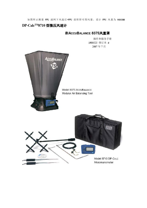
风速测量仪说明书
设置死区滞后开或关……………………………………………………………………………26
校准微压风速计(人工校准)…………………………………………………………………27
选择人工校准或出厂校准………………………………………………………………………27
第二章拆箱和建立………………………………………………5
拆箱………………………………………………………………………………………………5
准备仪器…………………………………………………………………………………………6
交流转换器供电给微压风速计…………………………………………………………………6
电池供电给微压风速计…………………………………………………………………………6
第一章简介…………………………………………………………1
仪器叙述…………………………………………………………………………………………1
微压风速计………………………………………………………………………………………2
微压风速计………………………………………………………………………………………2
标准器械…………………………………………………………………………………………3
邮编:55126
传真:(651)490-3824
质保和责任限制(自2000年7月生效)
本公司保证产品如下内容:按操作手册的指导进行操作和使用,自购买日起,在2年内将不会出现制造和材料的质量问题。
此保单同样适用以下情况:
a.风速仪或者其他指明的部件中的热线或者热膜传感器,以及保单上提到的附件,自购买日3个月内提供保证。
空气流量探针与微压风速计的连接……………………………………………………………10
风速温度测量仪说明书

1 234 5Vane probe thermo-anemometerDescription of the device1. OK key2. Backlight key3. Select key4. Backlight key On/Off/Esc key5. Hold/min/max keyL V 110 - L V 111- L V 117(1)All the accuracies indicated in this technical datasheet were stated in laboratory conditions, and can be guaranteed for measurements carried out in the same conditions, or carried out with calibration compensation.Once the measurement is frozen:• Press on "Hold/min/max".The device displays the maximum value of velocity or airflow measured since the last questioning at the top of the screen and the minimum value of velocity or airflow measured since the last questioning at the bottom of the screen.• Press again on "Hold/min/max".The device displays the maximum value of temperature measured since the last questioning at the top of the screen and the minimum value of temperature measured since the last questioning at the bottom of the screen.• Press on "On/Off/Esc" to return to the measurements display.Display the minimum and the maximum• Turn on the de device by pressing on "On/Off/Esc".The device displays its name "LV110", "LV111" or "LV117".• Put the probe to the required location.The device displays the velocity and temperature measurement.Perform a measurementDuring a measurement:• Press once on "Hold/min/max"."Hold" appears on screen and the measurement is frozen.• Press on "On/Off/Esc" to exit the hold function. The device returns to the measurement display.Freeze the measurement The device is on and displays the measurement.• Press on "OK"."START" displays on screen.• Press on "OK", the average calculation is launched, "END" displays on screen,"AVG" blinks.• Press on"OK" to stop the calculation, the average displays.• Press on "OK" to display the maximum and minimum values measured during the calculation of this average.• Press on "On/Off/Esc" to exit the average function and return to the measurements display.Perform an average in velocityIt is possible to display and to measure the airflow in place of the velocity. The device is on and displays the velocity and temperature measurements.• Press on "Select".• "MODE" blinks on screen.• Press on "OK"."VELO" blinks at the bottom of the screen.• Press on "Select"to select the "FLOW" mode then press on "OK" to validate.Depending on the device type, "CIRC", "K 25 85", "CONE" or "RECT" blinks at the bottom of the screen.• Press on "Select" to select rectangular "RECT", "CIRC", "K 25 85" (LV110) or "CONE" (LV111) for a measurement with an airflow cone then press on"OK".If "RECT" or "CIRC" is selected, the measuring unit of the type of duct displays.• Press on "Select" to select the unit: mm or inch then press on "OK" to validate.• If the type of selected duct is circular: "DIAM" displays and the first digit blinks.Press on "Select" to select its value then press on "OK" to validate. Perform the same procedure to select the values of the following digits (to return to the previous digit press on "On/Off/Esc"). When the last digit is adjusted, press on "OK" to validate. The device returns to the display of airflow and temperature measurements.• If the type of selected duct is rectangular: "LENGT" displays on screen and the first digit blinks.Press on "Select" to select its value then press on "OK" to validate. Perform the same procedure to select the values of following digits (to return to the previous digit press on "On/Off/Esc"). When the last digit is adjusted, press on "OK".Display and measure the airflowAdjust the deviceDevice drop-down menuSelect the measuring unit in velocity The device is on and in velocity mode.• Press on "Select" until "UNIT" blinks on screen.• Press on "OK".The unit currently used blinks on screen.• Press on "Select" until the required unit appears: m/s, fpm or km/h.• Press on "OK" to validate the unit selection. "UNIT" blinks on screen.•Press on "On/Off/Esc" to return to the measurements display."WIDTH" to adjust the width displays on screen, perform the same procedure to select the digits value, when the last digit is adjusted, press on "OK" to validate. The device returns to the display of airflow and temperature measurements.• If "K 25 85" is selected (LV110): the device returns to the measurements display.• If "CONE" is selected (LV111): "CONE" displays on screen and the cone type blinks: K35, K75, K120, K150.• Press on "Select" to select the type of cone, then press on "OK" to validate. The device returns to the display of airflow and temperature measurements.The length, the width and the section diameter are adjustable from 1 to 3000 mm.Select the measuring unit in airflow The device is on and in airflow mode.• Press on "Select" until "UNIT" blinks on screen.• Press on "OK"The unit used currently blinks on screen.• Press on "Select" until the required unit appears: m 3/h, L/s, cfm or m 3/s.• Press on "OK" to validate the unit selection. "UNIT" blinks on screen.•Press on "On/Off/Esc" to return to the measurements display.N T _E N – p o r t a b l e -L V 110-L V 111-L V 117 – 10/11/17 – N o n -c o n t r a c t u a l d o c u m e n t – W e r e s e r v e t h e r i g h t t o m o d i f y t h e c h a r a c t e r i s t i c s o f o u r p r o d u c t s w i t h o u t p r i o r n o t i c e.The device is on.• Press on "Backlight" to activate the device backlight.• Press again on this key to deactivate the backlight.Activate the backlight• Remove the front part at the back of the device.• Change the old batteries by AAA LR03 1.5V batteries.• Replace the front part.Change the batteriesSelect the measuring unit in temperature The device is on and displays the measurements.• Press on "Select" until "UNIT" blinks on screen with the unit temperature displayed below.• Press on "OK".The unit currently used blinks at the bottom of the screen.• Press on "Select" until the required unit appears: °C or °F .• Press on "OK" to validate. "UNIT" blinks on screen.• Press on "On/Off/Esc" to return to the measurements display.Adjust the auto shut-offThe device is on and displays the measurement.• Press on "Select" until "AUTO OFF" blinks on screen.• Press on "OK".The time before device auto shut-off blinks at the bottom of the screen.• Press on "Select" until the required time before auto shut-off appears: 15, 30, 45, 60, 75, 90, 105, 120 minutes or OFF • Press on "OK" to validate. "AUTO OFF" blinks on screen.•Press on "On/Off/Esc" to return to the measurement.Activate or deactivate the keys beepThe device is on and displays the measurement.• Press on "Select" until "BEEP" blinks on screen.• Press on "OK"."OFF" or "ON" blinks on screen.• Press on "Select" to activate the keys beep "ON" or deactivate it "OFF".• Press on "OK" to validate. "BEEP" blinks on screen.•Press on "On/Off/Esc" to return to the measurement display.。
多功能风速仪产品说明书

AM-4836V 风向
AM-4836C
量程参数
量程 分辨率
准确度
m/s (米/秒) 0.4~45.0 0.1 ±(2%n+0.1m/s)
km/h (千米/时) 1.4~162.0 风速
ft/min(呎/分) 80~8860
0.1 ±(2%n+0.1km/h) 0.1 ±(2%n+1ft/min)
——
低摩擦方向指针
温度
热敏电阻
自动关机
0~9 分钟之间任意设定
温度 操作环境
湿度
0~50°C (32~122°F) <80 %RH
电源 主机
4 节 7 号电池 156x67x28mm ( 6.1x2.6x1.1inch)
尺寸 传感器
重量(含电池)
叶轮:直径 72mm 3杯:65x65x115mm
——
方向:86x69x115mm
260g
375g
标准配置
主机
手提便携箱(B04) 手提便携箱(B10)
使用说明书
叶轮
三杯传感器
——
方向指针
可选附件
USB 联机线及软件
蓝牙适配器及软件
南北潮商城|www.nbchao.com
±22.5°
浪高(米)
0~14
0.1
±0.1
温度
14~140°F 0.1°F
0.9°F
-10~60°C 0.1°C
0.5°C
产品型号: AM-4836V AM-4836C
应用特点
广泛应用于锅炉、制冷、暖通、通风管道、环境监测、 航海测量中的数据采集,以及天气预报、野外作业和 消防部门的数据采集。 * AM-4836V可测量风速、风温、浪高、风级和风量等。 * AM-4836C不仅可以测量以上参数,还可测量风向。 * 带存储功能,可存储 24组数据。 * 具有最大值锁存,多种单位转换,自动关机等功能。 * 采用 USB 线、蓝牙数据输出,与 PC 进行通讯。
- 1、下载文档前请自行甄别文档内容的完整性,平台不提供额外的编辑、内容补充、找答案等附加服务。
- 2、"仅部分预览"的文档,不可在线预览部分如存在完整性等问题,可反馈申请退款(可完整预览的文档不适用该条件!)。
- 3、如文档侵犯您的权益,请联系客服反馈,我们会尽快为您处理(人工客服工作时间:9:00-18:30)。
C C Y Y--22001100A A数数字字风风速速仪仪说说明明书书
一.概述
1.用途
CY-2010A数字风速仪是用于测量风速的袖珍型测量仪,该仪器广泛用于环保、劳动卫生、体育、科研、公共场所及农业等方面的采暖通风、室内环境、超净间、设置在风洞内的模型试验、管道内的风速压力测试、空调检修及能力试验、地铁隧道的通风检测、工厂生产监测、建筑劳动作业现场环境卫生管理、空气调节等。
该仪器小巧,便于室内及室外使用。
2.简介
CY-2010A数字风速仪是一种热球式风速仪,本仪器由探头和电路二部分组成,探头经过导线连接到主板上,测量时将探头直接暴露在空气中,气流的变化而影响到探头阻止的变化,从而使主板的电流发生变化,经过增益和逻辑处理后,显示为当前的风速值,由液晶直接显示出来。
该仪器采用集成电路设计,具有灵敏度高、体积小、重量轻、操作简单、数字直读等优点。
该仪器采用交直流两用供电方式,直流采用500mA,12.6V锂离子充电电池,交流是用专用充电器直接给仪器供电,因此方便可靠。
二.工作原理
CY-2010A数字风速仪是探头阻值变化而产生不同的电流的原理制成的。
灵敏度极高的探头在遇到不同风速时使其冷却程度不同,阻值变化不同,从而产生的电流也不同,将电流信号转化为电压信号,经过主板进行放大,经增益调整、逻辑信号分离、线性化校正,将非线性信号转换成线性信号并由面板上的液晶显示器直接显示出风速的数值。
三.仪器的结构及功能介绍
(一)结构图
(二)功能介绍
1 .液晶屏幕
2 . POWER电源开关按键
3 . HOLD保持按键
4 . 机壳
5 . 充电器插口
6 . 电缆线
7 . 拉杆
四.技术参数
1 . 测量范围:A型0—10m/s B型0—30m/s
2 . 分辨率:0.01m/s
3 . 精确度:±(读数×2%+0.2)m/s
4 . 4位字段液晶显示
5 . 工作环境:5℃—50℃清洁空气中的风
6 . 电源:①锂离子充电电池
②AC适配器(选择性)
7 . 规格:主体:135×70×30mm
探头:160mm—422mm可拉伸探杆
电缆:75mm可拉伸弹簧电缆线
8 . 重量:0.28Kg
五.操作说明
1 . 开机检测,按POWER键仪器加电,几秒钟后仪器显示回到“0.00”,
这时已经进入测试状态,待仪器充分稳定后开始测试。
2 . 将仪器拿到测试地点,拉开拉杆,漏出传感器探头,使传感器朝向风
速方向,待液晶显示较为稳定,所显示的数值即为所测得风速。
此时
按下“HOLD”键,液晶保持闪烁显示所测得数值,再按下”HOLD”
键又回到测试状态。
可多次测量取其平均值。
(注意:人的呼吸远离拉杆中的传感器探头)
六.保养维护
根据检测频率的不同,每隔一段时间要对仪器进行一次保养。
仪器使用完毕必须关闭电源,当仪器长时间不用时,为了保护充电电池和程序稳定,每隔三个月要进行充电一次,并且不要放在腐蚀性气体过高的环境中。
请注意不要轻易打开仪器内部,如需进行较大维修,请寄回我公司由专业人员进行修理。
七.常见故障
八.附件
1. CY-2010A主机: 1台
2. 专用充电器: 1个
3. 说明书: 1份
4. 保修卡、合格证:各1份
九.售后服务
1.凡购买本公司CY-2010A产品,自购机之日起保修三年(电池保修1年)。
保修期内如果有问题,本公司将负责免费维修及更换部件,保修期外只收
取成本费,努力为用户服务是本公司的行为准则。
2.下列情况所出现的故障不在免费保修范围内
⑴因用户操作使用和保管不当引起的故障。
⑵因非专业人员修理和改造而引起的故障。
⑶因未经与本公司协商而在特殊场合使用引起的故障。
⑷因火灾、水灾、震灾等不可抗拒原因而引起的故障。
⑸因储存环境恶劣,而对仪器造成的损坏,(如酸性或碱性过大而对仪器
造成了腐蚀的)。
十.风速等级表。