E+H 一体化温度变送器 (Endress+Hauser) 技术资料 Omnigrad S TR62
e+h超声波流量计参数
e+h超声波流量计参数
e+h(Endress+Hauser,艾默生汉尼斯)的超声波流量计参数如下:
1. 测量范围:最小测量范围为0.15m/s,最大测量范围为
±40m/s。
2. 测量精度:标准精度为±0.5%(关于流体的速度和温度变化),高精度为±0.25%。
3. 测量介质:适用于各种液体,包括腐蚀性液体和带有杂质的液体。
4. 工作温度范围:-40°C到+160°C。
5. 输出信号:可选择4-20mA输出或者脉冲输出。
6. 液体压力:最大可承受16MPa的压力。
7. 电源:DC 24V,±10%。
8. 温度补偿:自动进行温度补偿。
9. 显示屏:LCD显示屏,可显示瞬时流量、累积流量和供电状态。
10. 通信接口:RS485接口,可实现MODBUS协议通讯。
以上就是e+h超声波流量计的主要参数介绍。
Endress+Hauser 设备操作手册说明书

Se trata de un manual de instrucciones abreviado; sus instrucciones no sustituyen a las instrucciones de funcionamiento del equipo.La información detallada sobre el equipo puede encontrarse en el manual de instrucciones del equipo y en la documentación complementaria del mismo:Disponibles para todas las versiones del equipo mediante:•Internet: /deviceviewer •Teléfono móvil inteligente/tableta: Endress+Hauser Operations AppInstrucciones de seguridad básicasRequisitos que debe cumplir el personalPara desempeñar sus tareas, el personal debe satisfacer los requisitos siguientes:‣Debe tratarse de especialistas que cuenten con una formación apropiada y cuya cualificación sea adecuada para llevar a cabo dichas funciones y tareas ‣Es necesaria la autorización correspondiente por parte de la dirección/propiedad de la planta ‣El personal debe estar bien familiarizado con las normas nacionales correspondientes ‣Antes de empezar cualquier trabajo, deben haber leído y entendido las instrucciones que figuran en el manual, la documentación suplementaria y los certificados (según la aplicación)‣Seguir las instrucciones y cumplir con las condiciones básicas Uso previsto El Cerabar sirve para medir presiones absolutas y relativas en gases, vapores y líquidos. Los materiales del equipo de medición en contacto con el producto del proceso deben disponer de un nivel adecuado de resistencia a dichos productos.El equipo de medición puede utilizarse para realizar las siguientes mediciones (variables de proceso)•en cumplimiento de los valores de alarma especificados en "Datos técnicos"•en cumplimiento de las condiciones enumeradas en la documentación adicional, como el XA y este manual.Variable de proceso medida PMP23: presión relativa o presión absoluta Funcionamiento seguro Riesgo de lesiones ‣Use el equipo solo si está en buenas condiciones técnicas y funciona de modo seguro.‣El operario es responsable del funcionamiento sin interferencias del equipo.Zona con peligro de explosiónPara eliminar riesgos para el personal o la instalación si se usa el equipo en la zona homologada (p. ej., protección contra explosiones, seguridad para equipos a presión):‣Compruebe la placas de identificación para verificar que el equipo solicitado se puede utilizar del modo previsto en la zona homologada.‣Observe las especificaciones indicadas en la documentación complementaria,como la XA o ZD, que forma parte del Manual de instrucciones.Identificación del productoDirección del fabricanteEndress+Hauser SE+Co. KG Hauptstraße 179689 Maulburg, AlemaniaLugar de fabricación: Véase la placa de identificación.MontajeRequisitos para el montaje•Evítese la entrada de humedad en la caja durante la instalación o el manejo del equipo, o cuando se establece el conexionado eléctrico.•Para un conector M12 hecho de metal: No retire la capucha de protección (solo en IP69 y en la versión Ex ec) de la conexión con conector M12 hasta poco antes de establecer la conexión eléctrica.•No limpie ni toque la membrana de proceso con objetos duros y/o puntiagudos.•No retire la protección de la membrana de proceso hasta el momento mismo de instalarla.•La entrada de cable debe estar siempre firmemente apretada.•Oriente el cable y el conector hacia abajo cuando sea posible para evitar que la humedad (p. ej., agua de lluvia o condensación) penetre.•Proteja la caja ante los posibles golpes •Para equipos con una célula de medición de presión relativa y un conector de válvula o M12, se aplica lo siguiente:Si un equipo de medición caliente se enfría durante un proceso de limpieza (p. ej., con agua fría), durante un breve intervalo de tiempo, se desarrolla un vacío. Como resultado, podría entrar humedad en la célula de medición por el compensador de presiones (1).Riesgo de destrucción del equipoProducts Solutions ServicesManual de instrucciones abreviado Cerabar PMP23Medición de presión de procesoKA01600P/23/ES/01.22-00716112272022-09-01*71611227*71611227KA01600P‣En este caso, monte el equipo con el compensador de presiones (1) en orientación diagonal hacia abajo –cuando sea posible– o hacia un lado.Influencia de la posición de instalaciónSe admite la instalación con cualquier orientación. Sin embargo, la orientación puede originar un desplazamiento del punto cero, es decir, el equipo no indica cero como valor medido cuando el depósito está vacío o parcialmente lleno(véase el manual de instrucciones).Lugar de instalaciónMedición de presión en gasesMonte el equipo de tal forma que la válvula de corte quede por encima del punto de medición y la condensación pueda pasar así a proceso.Medición de presión en vaporesPara la medición de presión en vapores, utilice un sifón. Un sifón reduce la temperatura a casi la temperatura ambiente. Monte el equipo con el equipo de corte al mismo nivel que el punto de medición.Respete la temperatura ambiente máxima admisible del transmisor.Medición de presión en líquidos Monte el equipo con el equipo de corte al mismo nivel que el punto de medición.Medición de nivel•Instale el equipo siempre por debajo del punto de medición más bajo.•No instale el aparato en ninguna de las siguientes posiciones:•En la cortina de producto •En la salida del depósito •en la zona de influencia de una bomba de succión •O en algún punto del depósito en el que puedan actuar pulsos de presión procedentes del agitador.Conexión eléctricaConexión de la unidad de mediciónAsignación de terminalesL ADVERTENCIARiesgo de lesiones debido a la activación sin control de procesos.‣Desconecte la fuente de alimentación antes de conectar el equipo.‣Compruebe que los procesos de separación y purificación no se inician accidentalmente.L ADVERTENCIAEl equipo puede estar conectado a tensión de alimentación.Riesgo de explosión ‣Compruebe que la tensión de alimentación no está activa durante laconexión.‣Desconecte la fuente de alimentación antes de conectar el equipo.L ADVERTENCIA Una conexión incorrecta compromete la seguridad eléctrica.‣Según la norma IEC/EN 61010, debe proveerse un disyuntor independientepara el equipo.‣El dispositivo se debe instalar con un fusible de hilo fino de 500 mA (acción lenta).‣Si se va a utilizar el equipo de medición en una zona con peligro de explosión,la instalación también debe realizarse conforme a las normas estatales vigentes y a las instrucciones de seguridad o los dibujos de instalación o control.‣Todos los datos relativos a la protección contra explosiones figuran en una documentación Ex separada que puede solicitarse. La documentación Ex se suministra por norma con todos los equipos aptos para zonas con peligro de explosión.‣La fuente de alimentación del transmisor limita la corriente máxima a Ii =100 mA cuando el equipo se utiliza en un circuito intrínsecamente seguro (Ex ia).‣El equipo dispone de circuitos de protección contra la inversión de polaridad.Conecte el equipo de la siguiente forma:1.Compruebe que la tensión de alimentación corresponde a la especificada en la placa de identificación.2.Conecte el equipo como se indica en el diagrama siguiente.Para equipos con conexión por cable: no cierre el conducto de aire de referencia (véase (a) en los siguientes planos). Proteja el conducto de aire de referencia contra la entrada de agua/condensados.Salida de 4 a 20 mA Véase el manual de instrucciones para consultar otras opciones de conexión.Tensión de alimentación L ADVERTENCIA El equipo puede estar conectado a tensión de alimentación.Riesgo de explosión ‣Si el equipo de medición ha de utilizarse en una zona con peligro de explosión, la instalación del mismo debe cumplir las normas nacionales correspondientes así como las “Instrucciones de seguridad”.‣Todos los datos relativos a la protección contra explosiones figuran en una documentación Ex separada que puede solicitarse. La documentación Ex se suministra por norma con todos los equipos aptos para zonas con peligro de explosión.KA01600P Consumo de corriente y señal de alarma1)Para alarma MAX (ajuste de fábrica)。
e+h压力变送器

E+H压力变送器广州南创蔡工e+h压力变送器(Endress+Hauser恩德斯·豪斯,简称E+H公司)是一家专业生产及销售工业自动化仪表的跨国集团公司,e+h压力变送器其产品覆盖了物位、压力、流量、分析、温度、系统及罐区、记录仪及通讯等工业测量仪表,是世界范围内自动化领域的领导者之一。
e+h压力变送器公司创建于1953年,总部位于瑞士,e+h压力变送器在世界各地有40多个分支机构,并在中国设立了广州南创传感事业部,为e+h压力变送器提供最佳的服务与解决方案。
有超过5,800名员工在进行研究、开发、生产、销售和维护工作。
e+h压力变送器在德国、瑞士、法国、美国、日本等世界工业国成立了规模庞大的生产中心,其严格的品质管理和完整的质保体系均已达到ISO9001国际标准。
e+h压力变送器是开发高质量、高可靠性仪表的重要因素之一,40多年来,e+h压力变送器公司通过紧密联系市场,不断开发适销对路产品,受益匪浅,并已成为全方位的供应商。
e+h压力变送器公司总部e+h压力变送器公司,由瑞士工程师Georg H. Endress和德国银行家Ludwig Hauser创建于1953年,总部位于瑞士Reinach, 地处德国、瑞士和法国的交界处,先后在德国、瑞士、法国、美国、日本、中国等世界工业国成立了规模庞大的生产中心,全球雇员达到6,077名,拥有70个独立的子公司分布在全球,其严格的品质管理和完整的质保体系均已达到ISO9001国际标准。
2006年,全球销售额达到了10亿欧元。
e+h压力变送器有:德国E+H压力仪表、德国E+H流量仪表、德国E+H物位仪表、德国E+H变送器、德国E+H电极、德国E+H物位计、德国E+H清洗济、德国E+H电磁流量计、德国e+h压力变送器。
e+h压力变送器部份特价清单如下:e+h压力变送器温度变送器(load cells)TST310-A7B1A3F3C1Ae+h压力变送器温度变送器TMT122-A31AAe+h压力变送器音叉液位开关FTL50AGQ2AA4G5ATL51AGR2BB2G5A,L=148mmCLD132-PMV118AB2CLD132-PMV118AB250W6H-UD0A1AA0AAAWTR25-AA21XC3000 L=180mmFMU90-R11CA161AA3Ae+h压力变送器恩德斯豪斯(E+H)超声波物位传感器FDU91-RG1AAFTL50-AGR2AA4G5Ae+h压力变送器恩德斯豪斯(E+H)电磁流量计53H08-KA0B1AC1AHAJCPS11-2AS2ESAe+h压力变送器恩德斯豪斯(E+H)质量流量计80M08-AS2CAADAA8AA72W80-SD0AA1AAA4AW83I41-AD2WAAABAGAAe+h压力变送器音叉液位开关FTL50-AGQ2AA2G4Ae+h压力变送器压力变送器PMC45-RE11P2JIAL451506784e+h压力变送器恩德斯豪斯(E+H)压力开关PTC31-A1A1ZH1AD1APTC35-A1A13P1PL4AFMU41-4RB2C2e+h压力变送器恩德斯豪斯(E+H)质量流量计80M40-AS2AAAAAAAA880M50-AS2AAAAAAAA880I50-AD2WAAAAAAA880I40-AD2WAAAAAAA8FTI56-AAD1RV143A1A L=800MMFTI56-AAD1RV143A1A L=1100MMe+h压力变送器音叉液位开关FTL20-3325RMA421-A21A2AFTR325-A1E1e+h压力变送器压力变送器PMC131-A15F1A1Se+h压力变送器恩德斯豪斯(E+H)溶解氧测量变送器COM253-DX0005e+h压力变送器恩德斯豪斯(E+H)溶解氧传感器COS41-2FCY A611-0Ae+h压力变送器恩德斯豪斯(E+H)雷达物位计FMR240-A5E1GGJAA2Fe+h压力变送器恩德斯豪斯(E+H)超声波物位变送器FMU90-J11CA212AA3AFDU95-J1G1A50H15-KB1A1AA0AAAADB50-AC22BB12EG2Ae+h压力变送器音叉液位开关FTL51-AGR2DB1G5Ae+h压力变送器涡街流量计72W1F-SBOAA1AAA4AWe+h压力变送器涡街流量计72F15-SEOBA1AAA4AW DN=20 FMU41-ARB2A250W65-UA0A1AA0ABAW50W2H-UC0A1AA0ABAWe+h压力变送器压力变送器PMC71-ABA1E2GHAAAe+h压力变送器涡街流量计72F25-SE0AA1AAA4AW72F50-SE0AA1AAA4AWFMP40-ABB2CMJB21AA,L=6000mmFMR250-A5E1GGJBA2K53H50-2HOB1AAOAGAJFMU231E-AA42e+h压力变送器音叉液位开关FTL51-AGR2DB1G4AFTW360-G1XJD1FMI51-A1BTDJB3A1A L=500MMe+h压力变送器恩德斯豪斯(E+H)导波雷达物位计FMP451C-AKCGKB21A2A L=1900mm50W1F-UC0A1AA0AAAAFMD77-ABA7H22FBAAA80M50-AS2AAAAAAAAACPF201-C1Ae+h压力变送器恩德斯豪斯(E+H)PH/ORP电极CPS11-1AA2GSACPF201-A1Ae+h压力变送器电源板50096745CUM253-TU8005e+h压力变送器恩德斯豪斯(E+H)PH测量变送器CPM253-PR8005PMP41-RE13S2J11T1FMP40-1AA2CQJB21AA L=10500MMe+h压力变送器音叉料位开关FTM51-AGG2L4A12AA L=500MM80F25-AD2SAAAAAAAAe+h压力变送器静压式液位计FMB70-ABA1M12TKCAAFHX40-A1A83F25-AD2SAABABHAAe+h压力变送器静压式液位计FMX167-A2ABE1C3PMC41-RG25M2J11R1e+h压力变送器恩德斯豪斯(E+H)音叉料位开关FTM50-AGJ2A4A32AAe+h压力变送器恩德斯豪斯(E+H)音叉料位开关FTM52-AGG2B4A32AA L=4000MM恩德斯豪斯(E+H)音叉料位开关FTM51-AGG2L4A32AA L=300MMCPM253-PR8010FTS20FMU43-AMD2A5FMU40-AND2A5COM253-DX0305COS41-2F恩德斯豪斯(E+H)测量变送器CUM253-TU0305e+h压力变送器恩德斯豪斯(E+H)浊度分析仪CUS41-W280F80-AD2SAACABBAAe+h压力变送器恩德斯豪斯(E+H)温度变送器TMT122-A31AA80F80-AD2SAP4ABBAAe+h压力变送器电源模块52006197FMR250-A6E2CMJBA2K80M50-AS2AAAAAAAAAe+h压力变送器恩德斯豪斯(E+H)音叉料位开关FTM50-AGG2A4A32AA80F40-BD4CAAAAAAAAFMU42-APB2A22A 二线制0-10米量程带表头e+h压力变送器电极支架CPA111-41C80F40-BD2CAAAAAAAA80M40-AS2AAAAAAAA支架CPA111-OOA支架CPA111-30C电极线:CPK9-NAA1APH电极:CPS11-2AS2ESA80F40-AD2SAA5AAAAA80F50-AD3SAA5AAAAA80F40-AD4SAAAAAAAAPMP71-AAA1M21GPNAAA80M40-AS2AAAAAXXXX83F50-AAASABBABAC2FMI51-A2AGEJB3A1A,L3=100mm,L1=800mm 50P40-AF1A1AA0BAAW83F25-AD2SAAAAAAAA50P40-AF1A1AA0BAAWFMX167-A2AMF1C350P80-ECOA1AA0AAAAFMR250-A4E1GGJAA4MCPS11D-7BA41CPS11-1BA2GSAFMP45-AAARGJG31A4A L=35Me+h压力变送器恩德斯豪斯(E+H)压力变送器PMC131-A15F1A1SCYK10-G881 L=7mCPA240-30AB110CM42-MGA000EAZ00CYK10-G101 L=10米CLS21-C1N2ACPA640-C11150P1H-EC0APAA0A5AA50P1H-ECOAPAAOA5AAPMC41-RE11P1A11M1FMU230A-AA32FMU40-ARG2A283F1H-AD1SAAAAAAAAe+h压力变送器恩德斯豪斯(E+H)音叉料位开关FTM21-AA245ACYK10-A051CPA250-A00CPA250-A0080F40-AD4SAABABAACP11D-7AA21 量程0-12FMU43-APG1A2FMI51-A1ARCJA1A1A 1800mmHART手操器DXR375-HR1EKLUFMG60-31D1T1B1A80F50-AD3SAABAAAAA80I50-AD2WABAAAAAA恩德斯豪斯(E+H)硅表试剂CAY643-V10AAE恩德斯豪斯(E+H)硅表清洗剂CAY641-V10AAE恩德斯豪斯(E+H)硅表维护包CA V740-5A恩德斯豪斯(E+H)标准液CAY642-V10C01AA恩德斯豪斯(E+H)标准液CAY642-V10C01AAE恩德斯豪斯(E+H)超声波液位计FMU230E-AA32 (2线制、量程0~4m) 恩德斯豪斯(E+H)超声波液位计FMU231E-AA32(2线制、量程0~7m) e+h压力变送器超声波液位计FMU41-ARH2A2 四线制量程八米恩德斯豪斯(E+H)涡街流量计电源板50086771恩德斯豪斯(E+H)涡街流量计放大器板5009351080F40-AAASAABABAAAFMG60-A1A1S1A1A50P25-EA2A1AA0AAAAFMP40-ABB2GRJB21AA L=1000MM雷达物位计FMR250-A5E1GGJAA2Ke+h压力变送器雷达物位计FMR250-A6E1XCJBB2KCPS12-0NA2ESA50W32-UA0A1AA0AAAA50W40-UA0A1AA0AAAA恩德斯豪斯(E+H)静压式液位计FMX167-A2CBF1C3FMR245-24CQKAA4A超声波液位计FMU40-ARB2A4恩德斯豪斯(E+H)静压式液位计FMX167-A2BBF1C383F08-AD2SAA31AAAFPMC71-ABA1C2GAAAUe+h压力变送器恩德斯豪斯(E+H)差压变送器PMD75-ABA7L21BAAA PMC71-ABA1P2GAAAAPMD75-ABA7L21BAAUCPF81-LH11C4FTM50-AGX2K4A12AA超声波液位计FMU40-ARB2A4DK5HA-H8AAC150H08-A00A1AA0AAAA+DK5HA-H8AAC130A T08-BD1AA11A21BFTL20-001680M50-AS2AABAAAAAAFTL51-AGR2DB4G5AFTM21-AG345APMC41-RE22FBJ11M1CPS91-2B02ESAe+h压力变送器超声波液位计FMU230E-AA32热导式流量计65I-20AB1AD1AAABAA热导式流量计65F15-AE2AG1AABAA热导式流量计65F25-AE2AG1AABAAFTC260-AA4D180F40-AD2SAAAAAAAACPS11D-7AA21CLS21-C2A4ACLM223-CD0110FTI51-AAA1RDJ43A1A L1=305mmTR10-AAA1CASYI3000 L=75MMFTI51-AAA1RDJ43D1A L1=305mm雷达液位计FMR245-A3CFKAA2AFAR10-6B恩德斯豪斯(E+H)超声波液位计FMU231E-AA32FTM51-AGG2L4A32AA L=450MMe+h压力变送器恩德斯豪斯(E+H)超声波流量计FMU90-R11CA131AA3A 恩德斯豪斯(E+H)超声波物位传感器FDU91-RG1AA10W40-UA0A1AA0A4恩德斯豪斯(E+H)超声波物位变送器FMU90-R11CA133AA1A电导率测量传感器CLS12-B1D1A电导率分析仪CLD132-WV A138AB2余(总)氯分析仪传感器CCS140-NFTL51-KAF2BB4G5A L=300MM恩德斯豪斯(E+H)超声波物位传感器FDU93-RG1A恩德斯豪斯(E+H)PH电极CPS11-2BA2ESACPS71D-7BB21e+h压力变送器恩德斯豪斯(E+H)PH电极CPS11-2AA2ESA压力变送器PMC131-A12F1A1R电导率测量变送器CLM253-ID0010电导信号转换器FTW325-B2B1A无膜法溶解氧传感器COS61-A1F0PMC131-A11F1A1Se+h压力变送器PH测量变送器CPM253-MR1005FMG60-A1A1D1A1AFHX40-A1A80A04-ASVW AAAAAAAAFTM50-AGG2A4A32AA恩德斯豪斯(E+H)超声波液位计FMU41-ANB2A4FMG60-A1A1D1A1AFHX40-A1ACLS50-A1C2PMC71-ABA1H2B3AAAFMR231-ABGNJAA2AAFMG60-A1A1A1D1A83M25-ASAAABABBAAB10H50-5F0A1AA0A5AACUM750-1E0BACUS70-1A2AFTM30-A4DA180I40-AD2WABAAAAAA72F1H-SE0AA1AAA4AW83F50-AAASABBABAC2FMU43-APG2A2FMU860-R1A1B1FTL51-ABD2DB1G5A, L=118mmCPK9-NAA1ACPM253-MR0005CPA111-00BCPM253-PR0505CPS11-1AS2ESAe+h压力变送器恩德斯豪斯(E+H)PH电极CPS11-2BA2ESAFTM260-G4B恩德斯豪斯(E+H)超声波液位计FMU40-ANB2A2恩德斯豪斯(E+H)超声波物位传感器FDU86-RG2FAU40-2NFMU860-R1A1B1CPS11D-7BA2G83I50-AD2WAAAAAGAAFMU862-R1A1A1e+h压力变送器恩德斯豪斯(E+H)热电偶温度计TC10-A6D3BHSHHA400/0-600deg.c 80F15-AD2SAAAAAAAACLS16-3D2A1PFTL50-KGM2AA4G5A72F25-SK0AA1CAB4AWFMX167-A1ABA1B7FMG60-A1A1A1D1A53H02-KAOB1AC1AHAAe+h压力变送器恩德斯豪斯(E+H)超声波物位传感器FDU86-RG1e+h压力变送器恩德斯豪斯(E+H)超声波物位变送器FMU860-R1A1A1FTM31-A43A1A L=2.5MFTM31-A43A1A L=1.8MCPS41-2AC2ESSCPA25-A0050P40-AA1A1AA0AAAACPS11-2AS2ESACYK10-A101FMX167-A1ABA1B7CPS11D-7BA21PMD75-2AA7D21BAAAPMD75-2AA7C21BAAAPMC71-ACA1S2RAAAAPMC71-ACA1P2RAAAACLS15-B3D1Ae+h压力变送器温度变送器TMT162/TMT165 TMT182温度变送器CLM223-IS0005CPM223-PR0005CPM223-IS0005CPS11D-7BA21CYK10-A101。
E+H Omnigrad M TR12 TC12 一体式温度计技术资料
Products
Solutions
Services
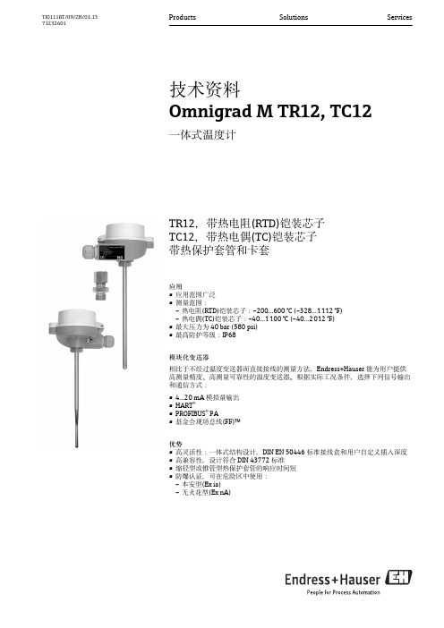
技术资料 Omnigrad M TR12, TC12
一体式温度计
TR12,带热电阻(RTD)铠装芯子 TC12,带热电偶(TC)铠装芯子 带热保护套管和卡套
应用 • 应用范围广泛 • 测量范围: – 热电阻(RTD)铠装芯子:–200…600 °C (–328…1 112 °F) – 热电偶(TC)铠装芯子:–40…1 100 °C (–40…2 012 °F) • 最大压力为 40 bar (580 psi) • 最高防护等级:IP68 模块化变送器 相比于不经过温度变送器而直接接线的测量方法,Endress+Hauser 能为用户提供 高测量精度、高测量可靠性的温度变送器。根据实际工况条件,选择下列信号输出 和通信方式: • • • • 4…20 mA 模拟量输出 HART® PROFIBUS® PA 基金会现场总线(FF)™
Omnigrad M TR12 和 TC12 温度计采用一体式结构设计。接线盒为铠装芯子的机械和电气连接部 件。铠装芯子中的实际温度计位置为铠装芯子提供机械保护。无需中断过程,即可更换和标定铠 装芯子。陶瓷接线端子块或变送器均可安装在接线盒内的垫圈上。通过卡套可以将温度计安装在 管道中或罐体上,卡套螺纹规格可以在常用卡套中选择:(→ 16) 测量范围 • 热电阻(RTD):–200…600 °C (–328…1 112 °F) • 热电偶(TC):–40…1 100 °C (–40…2 012 °F)
9 mm (0.35 in) 11 mm (0.43 in) 12 mm (0.47 in)
t50 t90 t50 t90 t50 t90
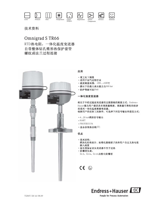
Endress+Hauser温度传感器和压力传感器说明书

Application •Fine Chemicals•Petrochemical industry •Power stations•Environmental engineering •Measuring range:–Resistance insert (RTD):–200 to 600 °C (–328 to 1 112 °F)–Thermocouple (TC):–40 to 1 100 °C (–40 to 2 012 °F)•Static pressure range up to 75 bar dependent on the used process connection •Protection class: IP66/68Head transmitterAll Endress+Hauser transmitters are available with enhanced accuracy and reliability compared to directly wired sensors. Easy customizing by choosing one of the following outputs and communication protocols:•Analog output 4 to 20 mA •HART ®•PROFIBUS ® PA•FOUNDATION Fieldbus™Your benefits•For plug-in/screw-in with sliding compression fitting •High degree of flexibility thanks to modular design with standard terminal heads as per DIN EN 50446 and customer-specific immersion lengths•High degree of insert compatibility and design as per DIN 43772•Types of protection for use in hazardous locations:–Intrinsic Safety (Ex ia)–Flameproof (Ex d)–Non-sparking (Ex nA)Technical InformationOmnigrad S TR65, TC65Modular ThermometerTR65 with resistance insert (RTD)TC65 with thermocouple insert (TC)TI01031T/09/EN/01.1271161897Omnigrad S TR65, TC65Function and system designMeasuring principle Resistance thermometer (RTD)These resistance thermometers use a Pt100 temperature sensor according to IEC 60751. The temperaturesensor is a temperature-sensitive platinum resistor with a resistance of 100 W at 0 °C (32 °F) and a temperaturecoefficient a = 0.003851 °C-1.There are generally two different kinds of platinum resistance thermometers:•Wire wound (WW): Here, a double coil of fine, high-purity platinum wire is located in a ceramic support.This is then sealed top and bottom with a ceramic protective layer. Such resistance thermometers not onlyfacilitate very reproducible measurements but also offer good long-term stability of the resistance/temperature characteristic within temperature ranges up to 600 °C (1112 °F). This type of sensor is relativelylarge in size and it is comparatively sensitive to vibrations.•Thin film platinum resistance thermometers (TF): A very thin, ultrapure platinum layer, approx. 1 m mthick, is vaporized in a vacuum on a ceramic substrate and then structured photolithographically. Theplatinum conductor paths formed in this way create the measuring resistance. Additional covering andpassivation layers are applied and reliably protect the thin platinum layer from contamination and oxidation,even at high temperatures.The primary advantages of thin film temperature sensors over wire wound versions are their smaller sizes andbetter vibration resistance. A relatively low principle-based deviation of the resistance/temperaturecharacteristic from the standard characteristic of IEC 60751 can frequently be observed among TF sensors athigh temperatures. As a result, the tight limit values of tolerance category A as per IEC 60751 can only beobserved with TF sensors at temperatures up to approx. 300 °C (572 °F). For this reason, thin-film sensors aregenerally only used for temperature measurements in ranges below 400 °C (932 °F).Thermocouples (TC)Thermocouples are comparatively simple, robust temperature sensors which use the Seebeck effect fortemperature measurement: if two electrical conductors made of different materials are connected at a point, aweak electrical voltage can be measured between the two open conductor ends if the conductors are subjectedto a thermal gradient. This voltage is called thermoelectric voltage or electromotive force (emf.). Its magnitudedepends on the type of conducting materials and the temperature difference between the "measuring point"(the junction of the two conductors) and the "cold junction" (the open conductor ends). Accordingly,thermocouples primarily only measure differences in temperature. The absolute temperature at the measuringpoint can be determined from these if the associated temperature at the cold junction is known or is measuredseparately and compensated for. The material combinations and associated thermoelectric voltage/temperaturecharacteristics of the most common types of thermocouple are standardized in the IEC 60584 and ASTM E230/ANSI MC96.1 standards.2Endress+HauserOmnigrad S TR65, TC65Endress+Hauser 3AActive barrier RN221N - The RN221N (24 V DC, 30 mA) active barrier has a galvanically isolated output for supplying voltage to loop-powered transmitters. The universal power supply works with an input supply voltage of 20 to 250V DC/AC, 50/60 Hz, which means that it can be used in all international power grids. More information on this can be found in the Technical Information (see "Documentation").BRIA16 field display unit - The display unit records the analog measuring signal from the head transmitter and shows this on the display. The LC display shows the current measured value in digital form and as a bar graph indicating a limit value violation. The display unit is looped into the 4 to 20 mA circuit and gets the required energy from there.More information on this can be found in the Technical Information (see "Documentation").CMounted thermometer with head transmitter installed.Designå 2Thermometer design1Complete thermometer with terminal head and fixed thread 2Thermometer with sliding process connections 3Insert with terminal block mounted (example)4Insert with head transmitter mounted (example)MLInsertion lengthThermometers from the Omnigrad TR65 and TC65 series have a modular design. The terminal head is used as a connection module for the mechanical and electrical connection of the insert. The position of the actual thermometer sensor in the insert ensures that it is mechanically protected. The insert has flying leads, a ceramic connection socket or mounted temperature transmitter.Omnigrad S TR65, TC654Endress+HauserMeasuring range•RTD: –200 to 600 °C (–328 to 1 112 °F)•TC: –40 to 1 100 °C (–40 to 2 012 °F)Performance characteristicsOperating conditionsAmbient temperatureProcess pressureThe maximum process pressure depends on the used process connection. For an overview of the process connections which may be used, see chapter "Process connection" (®ä 13).Omnigrad S TR65, TC65Endress+Hauser 5Permitted flow velocity depending on the immersion lengthThe highest flow velocity tolerated by the thermometer diminishes with increasing immersion length exposed to the stream of the fluid. In addition it is dependent on the diameter of the thermometer tip, on the kind of measuring medium, on the process temperature and on the process pressure. The following figures exemplify the maximum permitted flow velocities in water and superheated steam at a process pressure of 1 MPa (10 bar).v (ft/s)L (in)v (m/s)0510152025303505010015020025030035040045050005101520253035050100150200250300350400450500v (m/s)L (mm)L (mm)AB2468101214161820L (in)2468101214161820153045607590105v (ft/s)0153045607590105 A0010867å 3Maximum flow velocityA Medium water at T = 50 °C (122 °F)B Medium superheated steam at T = 400 °C (752 °F)L Immersion length v Flow velocity-----Insert diameter 3 mm (0.12 in)- - -Insert diameter 6 mm (0.24 in)Shock and vibration resistance•RTD: 3G / 10 to 500 Hz according to IEC 60751•TC: 4G / 2 to 150 Hz according to IEC 60068-2-6Omnigrad S TR65, TC656Endress+HauserAccuracyRTD resistance thermometer as per IEC 607511)|t| = absolute value °CIn order to obtain the maximum tolerances in °F, the results in °C must be multiplied by a factor of 1.8.Permissible deviation limits of thermoelectric voltages from the standard characteristic for thermocouples as per IEC 60584 or ASTM E230/ANSI MC96.1:1)|t| = absolute value °C1)|t| = absolute value °COmnigrad S TR65, TC65Endress+Hauser 7Response timeCalculated at an ambient temperature of approx. 23 °C by immersing in running water (0.4 m/s flow rate,10 K excess temperature):Response time for insert without transmitter.Insulation resistance Insulation resistance ≥100 M W at ambient temperature.Insulation resistance between the terminals and the extension neck is measured with a voltage of 100 V DC.Self heatingRTD elements are passive resistances that are measured using an external current. This measurement current causes a self-heating effect in the RTD element itself which in turn creates an additional measurement error.In addition to the measurement current, the size of the measurement error is also affected by the temperature conductivity and flow velocity of the process. This self-heating error is negligible when an Endress+Hauser iTEMP ® temperature transmitter (very small measurement current) is connected.CalibrationEndress+Hauser provides comparison temperature calibration from –80 to +1 400 °C (–110 to +2 552 °F)based on the International Temperature Scale (ITS90). Calibrations are traceable to national and international standards. The calibration certificate is referenced to the serial number of the thermometer. Only the insert is calibrated.Omnigrad S TR65, TC65Material Process connection, insertThe temperatures for continuous operation specified in the following table are only intended as reference valuesfor use of the various materials in air and without any significant compressive load. The maximum operationtemperatures are reduced considerably in some cases where abnormal conditions such as high mechanical loadoccur or in aggressive media.1)Can be used to a limited extent up to 800 °C (1472 °F) for low compressive loads and in non-corrosive media. Pleasecontact your Endress+Hauser sales team for further information.8Endress+HauserOmnigrad S TR65, TC65Endress+Hauser9ComponentsFamily of temperature transmittersThermometers fitted with iTEMP ® transmitters are an installation-ready complete solution to improvetemperature measurement by significantly increasing accuracy and reliability, when compared to direct wired sensors, as well as reducing both wiring and maintenance costs.PC-programmable TMT180 and TMT181 head transmittersThey offer a high degree of flexibility, thereby supporting universal application with low inventory storage. The iTEMP ® transmitters can be configured quickly and easily at a PC. Endress+Hauser offers the ReadWin ® 2000configuration software for this purpose. This software can be downloaded free of charge at . More information can be found in the Technical Information.HART ® TMT182 head transmitterHART ® communication is all about easy, reliable data access. It means that additional information on the measurement point can be obtained more cost-effectively. iTEMP ® transmitters integrate seamlessly into your existing control system and provide trouble-free access to a wide range of diagnostic information.Configuration is done using a hand-held device (Field Xpert SFX100 or DXR375) or a PC with configuration program (FieldCare, ReadWin ® 2000). AMS or PDB can also be used for configuration purposes. More information can be found in the Technical Information.HART ®-programmable iTEMP ® head transmitter TMT82The iTEMP ® TMT82 is a loop-powered device with two measurement inputs and one analog output. The device not only transfers converted signals from resistance thermometers and thermocouples, it also transfers resistance and voltage signals using HART ® communication. It can be installed as an intrinsically safe apparatus in hazardous areas, zone 1 and is used for instrumentation purposes in the terminal head, flat face as per DIN EN 50446. Swift and easy operation, visualization and maintenance by means of a PC using configuration software such as FieldCare, Simatic PDM oder AMS. Benefits are: dual sensor input, highest reliability, accuracy and long-term stability in critical processes, mathematic functions, thermometer drift monitoring, sensor back-up functionality, sensor diagnosis functions and sensor-transmitter matching using Callendar-Van Dusen coefficients. More information can be found in the Technical Information.PROFIBUS ® PA iTEMP ® head transmitter TMT84Universally programmable head transmitter with PROFIBUS ® PA communication. Conversion of various input signals into digital output signals. High accuracy over the complete ambient temperature range. Swift and easy operation, visualization and maintenance using a PC directly from the control panel, e.g. using operating software such as FieldCare, Simatic PDM or AMS. Benefits are: dual sensor input, highest reliability in harsh industrial environments, mathematic functions, thermometer drift monitoring, sensor back-up functionality,sensor diagnosis functions and sensor-transmitter matching using Callendar-Van Dusen coefficients. More information can be found in the Technical Information.FOUNDATION Fieldbus™ iTEMP ® head transmitter TMT85Universally programmable head transmitter with FOUNDATION Fieldbus™ communication. Conversion of various input signals into digital output signals. High accuracy over the complete ambient temperature range.Swift and easy operation, visualization and maintenance using a PC directly from the control panel, e.g. using operating software such as ControlCare from Endress+Hauser or NI Configurator from National Instruments.Benefits are: dual sensor input, highest reliability in harsh industrial environments, mathematic functions,Omnigrad S TR65, TC65thermometer drift monitoring, sensor back-up functionality, sensor diagnosis functions and sensor-transmittermatching using Callendar-Van Dusen coefficients. More information can be found in the Technical Information.Terminal heads All terminal heads have an internal shape and size in accordance with DIN EN 50446, flat face and athermometer connection of M24x1.5, G1/2" or 1/2" NPT thread. All dimensions in mm (in). The cable glandsin the diagrams correspond to M20x1.5 connections. Specifications without head transmitter installed. Forambient temperatures with head transmitter installed, see "Operating conditions" section.TA30H10Endress+HauserOmnigrad S TR65, TC65Endress+Hauser11Omnigrad S TR65, TC65 Design All dimensions in mm (in).å 4Dimensions of the Omnigrad S TR65 and TC651Complete thermometer with terminal head and fixed thread2Thermometer with sliding process connections3Insert with terminal block mounted4Insert with head transmitter mounted5Insert with flying leadsTL Screw-in lengthML Insertion lengthIL Total length of insertÆID Insert diameterWeight0.5 to 2.5 kg (1 to 5.5 lbs) for standard options.12Endress+HauserOmnigrad S TR65, TC65Process connection The process connection is the means of connecting the thermometer to the process. The following processconnestions are available:å 5Process connectionsSpare parts The following compression fittings are available as spare parts:Endress+Hauser13Omnigrad S TR65, TC65WiringWiring diagrams for RTD Type of sensor connection14Endress+HauserOmnigrad S TR65, TC65Wiring diagrams for TC Thermocouple wire colorsEndress+Hauser15Omnigrad S TR65, TC6516Endress+HauserInstallation conditionsOrientationNo restrictions.Installation instructionsparameters and the process to be measured must be taken into account (e.g. flow velocity, process pressure).•Installation possibilities: Pipes, tanks or other plant components•Recommended minimum immersion length: 80 to 100 mm (3.15 to 3.94 in)The immersion length should correspond to at least 8 times of the thermowell diameter. Example:Thermowell diameter 12 mm (0.47 in) x 8 = 96 mm (3.8 in). A standard immersion length of 120 mm (4.72 in) is recommended.•ATEX certification: Always take note of the installation regulations!Certificates and approvalsCE MarkThe device meets the legal requirements of the EC directives if applicable. Endress+Hauser confirms that the device has been successfully tested by applying the CE mark.Hazardous area approvalsFor further details on the available Ex versions (ATEX, CSA, FM etc.), please contact your nearest Endress +Hauser sales organization. All relevant data for hazardous areas can be found in separate Ex documentation.Other standards and guidelines•EN 60079: ATEX certification for hazardous areas •IEC 60529: Degree of protection of housing (IP code)•IEC 61010-1: Protection Measures for Electrical Equipment for Measurement, Control, Regulation and Laboratory Procedures.•IEC 60751: Industrial platinum resistance thermometers •IEC 60584 and ASTM E230/ANSI MC96.1: ThermocouplesOmnigrad S TR65, TC65Endress+Hauser 17•EN 50014/18: Electrical equipment for hazardous areas - General regulations/Flameproof enclosure "d"•DIN EN 50446: Terminal heads•IEC 61326-1: Electromagnetic compatibility (EMC requirements)PED approvalThe thermometer complies with paragraph 3.3 of the Pressure Equipment Directive 97/23/CE and is not marked separately.Test report and calibrationThe "Factory calibration" is carried out according to an internal procedure in a laboratory of Endress+Hauser accredited by the European Accreditation Organization (EA) to ISO/IEC 17025. A calibration which isperformed according to EA guidelines (SIT or DKD calibration) may be requested separately. The calibration is performed on the replaceable insert of the thermometer. In the case of thermometers without a replaceable insert, the entire thermometer - from the process connection to the tip of the thermometer - is calibrated.Ordering informationDetailed ordering information is available from the following sources:•In the Product Configurator on the Endress+Hauser website: ® Select country ®Instruments ® Select device ® Product page function: Configure this product •From your Endress+Hauser Sales Center:/worldwideProduct Configurator - the tool for individual product configuration •Up-to-the-minute configuration data•Depending on the device: Direct input of measuring point-specific information such as measuring range or operating language•Automatic verification of exclusion criteria•Automatic creation of the order code and its breakdown in PDF or Excel output format •Ability to order directly in the Endress+Hauser Online ShopDocumentationTechnical information:•Temperature head transmitter:–iTEMP ® TMT180, PC-programmable, single-channel, Pt100 (TI088R/09/en)–iTEMP ® PCP TMT181, PC programmable, single-channel, RTD, TC, Ω, mV (TI00070R/09/en)–iTEMP ® HART ® TMT182, single-channel, RTD, TC, Ω, mV (TI078R/09/en)–iTEMP ® HART ® TMT82, two-channel, RTD, TC, Ω, mV (TI01010T/09/en)–iTEMP ® PROFIBUS ® PA TMT84, two-channel, RTD, TC, Ω, mV (TI138R/09/en)–iTEMP ® FOUNDATION Fieldbus TM TMT85, two-channel, RTD, TC, Ω, mV (TI134R/09/en)•Application example:–RN221N active barrier, for supplying loop-powered 2-wire transmitters (TI073R/09/en)–RIA16 field display, loop-powered (TI00144R/09/en)Process connection:Compression fitting Omnigrad TA50 (TI091t/02/en)Hazardous area (ATEX) supplementary documentation:•RTD/TC Thermometer Omnigrad TRxx, TCxx, TxCxxx, ATEX II 1GD or II 1/2GD Ex ia IIC T6...T1(XA072R/09/a3)•RTD/TC Thermometer Omnigrad S TR/TC6x, ATEX II1/2, 2GD or II2G (XA014T/02/a3)•RTD/TC Thermometer Omnigrad S TR/TC6x, ATEX II 1/2 or 2G; II 1/2 or 2D; II 2G (XA00084R/09/a3)Instruments International Endress+Hauser Instruments International AG Kaegenstrasse 24153 ReinachSwitzerlandTel.+41 61 715 81 00Fax+41 61 715 25 00***************.comTI01031T/09/EN/01.12 71161897。
E+H 一体式温度计 (Endress+Hauser) 技术资料 Omnigrad S TMT142

输入信号
热电偶 (TC) 符合 NIST Monograph 175, IEC 584 标准
型号
测量范围
最小量程
J 型 (Fe-CuNi) K 型 (NiCr-Ni)
-210...+1200 °C (-346...2192 °F)
50 K
-270...+1372 °C (-454...2501 °F)
缩小偏差 (IEC 60584)
等级 偏差
1
+/-1.5 °C (-40...375 °C)
+/-0.004 |t| (375...750 °C)
1
+/-1.5 °C (-40...375 °C)
+/-0.004 |t| (375...1000 °C)
(ItI= 绝对温度值 (°C))
热电偶 (TC)
®பைடு நூலகம்
TMT142R TMT142C
RN221N
2 1P>VOGnrliPonuMepC7S3el1:ectPIC0001
HELP
0.7 bar I O
FieldCare ReadWin® 2000
Commubox
DXR375 HART® 䙊ؑ
一体式温度计的应用实例
Omnigrad S HART® TMT142C 是一款一体式温度计,带两线制变送器、热电偶输入 (J 型或 K 型 ) 和 模拟量输出。液晶 (LC) 显示屏中数字式显示当前测量值,棒图显示限定值偏差。TMT142C 可以通 过 HART® 手操器 (DXR375) 或 PC 机 (FieldCare 或 ReadWin® 2000 操作软件 ) 操作。 传感器结构符合 IEC 60751 标准,在所有典型环境条件下具有高可靠性和高性能。 测量部件为下列两种型号的合金热电偶:J 型 (Fe-CuNi) 或 K 型 (NiCr-Ni)。温度测量部件的量程取 决于热电偶类型。测量传感器 ( 可更换的热电偶铠装芯子 ) 安装在合适的热保护套管中。 采用压簧式结构,温度计铠装芯子始终与热保护套管的内部顶端接触,确保了过程至测量部件的 最佳热传递。变送器可以采用铝涂层外壳或不锈钢外壳 ( 可选 ),带或不带液晶 (LC) 显示。外壳、 热保护套管和电缆口的良好配合确保了至少具有 IP65 防护等级。 热保护套管可以是管材焊接制成,或采用棒材整体钻孔。热保护套管具有不同的类型,带多种过 程连接:螺纹、法兰或焊接型 ( 参考 “ 热保护套管 ”)。
一体化温度变送器说明书
Services Pressure Flow TemperatureLiquid AnalysisRegistrationSystemComponentsLevel SolutionsRTDOmnigrad S TR66-200...+600500barIP68Endress+Hauser4...20mA HARTPROFIBUS PA(FF)Ex d Ex ia ExnAOmnigrad S TR66B RIA261RIA261RIA2614...20mARIA2612.5V RIA261RIAA RN221N()Omnigrad S TR66RN221N 24VDC 30mA 20...250V DC/AC 50/60HzOmnigrad S TR66Omnigrad S TR661TPR100 2TPR3003456(6mm)Ex ia Ex nA(6mm)NTUA=U+TIL=U+T+N+41mmOmnigrad S TR66Pt100Pt100Pt100 -200...600IEC60751()4MPaOmnigrad S TR66()D1=35mm Q1=25mm Q2=18mm D1=30mmQ1=20mm Q2=14mmA T=50BT=400L 1.4401v4g/2...150HzIEC 60068-2-6Omnigrad S TR66RTD IEC607511)=()|t|IEC607510.4m/s10100V DC100MRTD RTDEndress+HauseriTEMPITS90Endress+Hauser RTD-80...+600:mm()6mmOmnigrad S TR661)800Endress+Hauser(/)%Omnigrad S TR66iTEMP 4...20mATMT180TMT181(PC )TMT182(HART)PCiTEMPPCEndress+HauserReadWin InternetHART iTempDXR275/375(FieldCare ReadWin PC AMSPDMTMT84(PROFIBUS PA)Callendar-Van Dusen -PROFIBUS PA TMT84PCFieldCare Simatic PDMAMSDIPFFTMT85PCEndress+Hauser Control NICallendar-Van Dusen-TMT85(FF)TMDIN43729form B(EN50014/18EN50281-1-1) XPmm Omnigrad S TR66Omnigrad S TR66mmOmnigrad S TR66IL U+T+L+41mmN T U123ID A Omnigrad S TR66D1Q1Df Q21200mmOmnigrad S TR661.5...5.5 kg()(ASME B16.5, ANSI B1.20.1)mm1) RF SORaised Face Slip()Endress + Hauser11Omnigrad S TR66(Pt100) TPR100 TPR300 316L/1.4401 MgO12Endress + HauserOmnigrad S TR66TMT18x()4...20 mA( () )( ( ( () ) ) )()TMT84/85()2 RTD /1 RTDEndress + Hauser13Omnigrad S TR66A-B C-D( B ) ) ( C D ) (A14Endress + HauserOmnigrad S TR66NCEndress + Hauser15Omnigrad S TR66CEOmnigrad S TR66 Endress+Hauser ExEC CE (ATEX CSA FM ) Endress+HauserIEC 60529 (IPIEC 61010-1 )IEC 60751IEC 43772EN 50014/18, DIN 47229EN 61326-1 (EMC)(PED)1 2.1(97/23/EC) CE EN 10204 3.1 Endress+Hauser DIN 43772 ( ) TZC138 TZC125IEC 60751 Endress+HauserTZC135 TZC133/13416Endress + HauserOmnigrad S TR66Omnigrad S TR66A C E H K L M ATEX II 1 GD EEx ia IIC ATEX II 2 GD EEx d IIC ATEX II 3 GD EEx nA II TIIS Ex ia IIC T4 TIIS Ex ia IIC T6 ATEX II 1/2 GD EEx d IICA B C YTA21H, TA30H, TA30H,, IP66 , IP66/IP68 , IP66/IP67;A B C D E F Y1 2 1 2 1 21/2" NPT 1/2" NPT 3/4" NPT 3/4" NPT M20 1.5 M20 1.5NB C E F G J YFitting69 mm; 316; N 1/2" NPT M 109 mm; 316; N 1/2" NPT M 148 mm; 316; N 1/2" NPT M 69 mm; A105; N 1/2" NPT M 109 mm; A105; N 1/2" NPT M 148 mm; A105; N 1/2" NPT M ... mm;B C D Y316Ti 316 316LT1 2 6 9D1DfQ1Q270 mm; 30 mm; 7 mm; 20 mm; 14 mm 75 mm; 35 mm; 7 mm; 24 mm; 14 mm 100 mm; 35 mm; 8 mm; 25 mm; 18 mm ... mm;UX Y... mm ... mm;TR66-()Endress + Hauser17Omnigrad S TR66Omnigrad S TR66 ( )CA CB CC CD CE CF CG CH CJ CK CL CM CQ CS CT CV JA JB JC JD JE JF YY 11 22 441" ANSI 150 RF SO ; A105 1" ANSI 150 RF SO ; B16.5; JPI; 316 1" ANSI 300 RF SO ; A105 1" ANSI 300 RF SO ; B16.5; JPI; 316 1" ANSI 600 RF SO ; A105 1" ANSI 600 RF SO ; 316 1 1/2" ANSI 150 RF SO ; A105 1 1/2" ANSI 150 RF SO ; B16.5; JPI; 316 1 1/2" ANSI 300 RF SO ; A105 1 1/2" ANSI 300 RF SO ; B16.5; JPI; 316 1 1/2" ANSI 600 RF SO ; A105 1 1/2" ANSI 600 RF SO ; 316 2" ANSI 300 RF SO ; A105 2" ANSI 600 RF SO ; A105 2" ANSI 600 RF SO ; 316 2" ANSI 300 RF SO ; 316 10K25A RF JIS B 2220 ; 316 10K40A RF JIS B 2220 ; 316 10K50A RF JIS B 2220 ; 316 20K25A RF JIS B 2220 ; 316 20K40A RF JIS B 2220 ; 316 20K50A RF JIS B 2220 ; 316 3/4" NPT-M 1" NPT-M R 3/4", JIS B 0203; 316B C D F G H 2 3 4 5TMT84 PA TMT85 FF TMT181 (PCP); TMT182 (HART); TMT180-A21 fix; 0.2 K, TMT180-A22 fix; 0.1 K, TMT180-A11 PCP; 0.2 K, TMT180-A12 PCP; 0.1 K,, , , ,-200/650 -50/250 -200/650 -50/250RTDA B C F G Y 2 3 6 7;;; -200/600 ; -200/600 ; -200/600 ; -200/600 ; -200/600 ; A: -200/600 ; A: -200/600 ; A: -200/600 ; 1/3B; 0/250 ; 1/3B; 0/250 , , , ,1x Pt100(WW); 2x Pt100(WW); 1x Pt100(WW); 2x Pt100(WW); 1x Pt100(WW); 1x Pt100(TF); 1x Pt100(TF); 1x Pt100(TF); 1x Pt100(TF);; -50/400 ; A; -50/250 ; -50/400 ; A; -50/250 ; -50/400 ; 1/3B; 0/150 ; -50/400 ; 1/3B; 0/150Y 0TR66-18Endress + HauserOmnigrad S TR66FA 006T/09/en TI 088R/09/en TI 070R/09/en TI 078R/09/en TI 138R/24/ae TI 134R/24/ae TI 079R/09/en TI 268T/02/ae TI 290T/02/ae XA 003T/02/z1 TI 236T/02/en XA 015T/02/z1 TI 091T/02/eniTEMP Pt TMT180 iTEMP PCP TMT181 iTEMP HART TMT182 iTEMP PA TMT84 iTEMP FF TMT85 iTEMP PA TMT184 Omniset TPR100 RTD Omniset TPR300 RTD (TPR100) (TPR300) Omnigrad TA50 TA55TA60TA70TA75Endress + Hauser19Omnigrad S TR664008 86 2580458 (021)24039600 24039700 (021)24039607 200241 E-mail: info@ 99 16 (010)59572888 (010)59572700 100176 E-mail: ehbj@B-D-22 (028) 66002128 (028) 66070084 (028) 66070085 610041 E-mail: ehcd@68 B 1606 (0531)86110426 (0531)86110584 250011 E-mail: ehjn@418 V207 (0551)2863897 (0551)2863887 230001 E-mail: ehhf@67 A2 1103 (025) 84805000 (025) 84805302 210009 E-mail: ehnj@19 2 2619 (0731) 8855487 8859768 (0731) 8856537 410006 E-mail: ehcs@628 A 2308 (027) 87854540 87854601 (027) 87665231 430070 E-mail: ehwh@1110 2101 (0755)33225328 33225325 (0755)33235326 (0755)33225327 518054 E-mail: ehsz@96-6 1208 (024) 86131178 (024) 86131799 110031 E-mail: ehsy@88 B 802 (029) 87651280 (029) 87651278 710068 E-mail: ehxa@368 812 (0451)85977500 85977600 (0451)85977100 150090 E-mail: ehhr@2 22 H (0991) 5587692 5587695 (0991) 5589109 830000 E-mail: ehxj@88 C1 8 (0871)3634650 (0871)3638622 650011 E-mail: konde@3355 13 606 (0431) 87025888 87027755 (0431) 87023666 130012 E-mail: ehcc@TI284T/28/zh/08.09。
E+H 溶解氧变送器 (Endress+Hauser) 技术资料 Liquisys M COM223_253
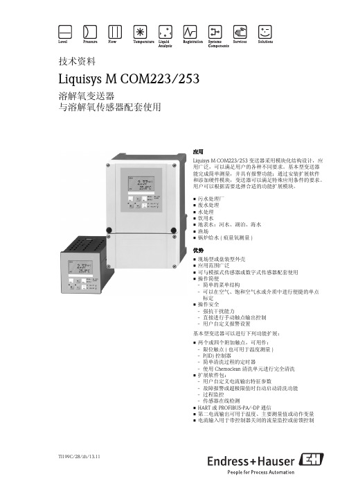
TI199C/28/zh/13.11技术资料Liquisys M COM223/253溶解氧变送器与溶解氧传感器配套使用应用Liquisys M COM223/253变送器采用模块化结构设计,应用广泛,可以满足用户的各种不同要求。
基本型变送器能完成简单测量,并具有报警功能;通过安装扩展软件和添加硬件模块,变送器可以满足特殊应用条件的要求。
用户可以根据需要选择合适的功能扩展模块。
•污水处理厂•废水处理•水处理•饮用水•地表水:河水、湖泊、海水•渔场•锅炉给水(痕量氧测量)优势•现场型或盘装型外壳•应用范围广泛•可与模拟式传感器或数字式传感器配套使用•操作简便- 简单的菜单结构- 可以在空气、饱和空气水或介质中进行便捷的单点标定•操作安全- 强抗干扰能力- 直接进行手动触点输出控制- 用户自定义报警设置基本型变送器可以进行下列功能扩展:•两个或四个附加触点,可用作:- 限位触点(也可用于温度测量)- P(ID)控制器- 简单清洗过程的定时器- 使用Chemoclean 清洗单元进行完全清洗•扩展软件包:- 用户自定义电流输出特征参数- 故障报警或超极限值时自动启动清洗功能- 过程监控- 传感器在线检测•HART 或PROFIBUS-PA/-DP 通信•第二电流输出可用于温度、主要测量值或动作变量•电流输入用于带控制器关闭的流量监控或前馈控制Liquisys M COM223/2532Endress+Hauser功能与系统设计基本型变送器的特点溶解氧浓度和氧分压测量溶解氧浓度的显示单位为mg/l 或%SAT ,氧分压的显示单位为hPa ,通过菜单选择。
如需要,可以选择同时显示温度值,也可以隐藏显示。
标定电流法溶解氧传感器无零点电流,仅需进行单点标定。
可以在空气和饱和空气水中进行标定,或在介质中进行参比标定。
荧光法溶解氧传感器在出厂前已经完成标定。
如需要,可以在空气中进行零点标定。
设置需要针对应用条件和操作人员定义不同的报警信号。
- 1、下载文档前请自行甄别文档内容的完整性,平台不提供额外的编辑、内容补充、找答案等附加服务。
- 2、"仅部分预览"的文档,不可在线预览部分如存在完整性等问题,可反馈申请退款(可完整预览的文档不适用该条件!)。
- 3、如文档侵犯您的权益,请联系客服反馈,我们会尽快为您处理(人工客服工作时间:9:00-18:30)。
传感器结构
TA21H型接线盒用于保护内置的温度变送器或接 线端,同时它也是电气连接的物理结构。 TR62的接线盒TA21 H遵循EN 50014/18、 EN 50281-1-1和EN 50281-1-2标准(用于危险场合的 隔爆认证标准,即EEx-d证书) 。 由与之 匹配的接 线盒 下的 延伸 部分和旋 盖组 成的 接线盒 确保 了高 防护 等级 。防 护等 级为 IP66...IP68。 旋盖同盒身间的连接链子使得仪表维护起来 更加的便利。 电气接口可单个,也可双个,同时有多种形 式可供选择:M20x1.5、1/2" NPT 、3/4" NPT或 G1/2"。
Endress + Hauser
Omnigrad S TR62
应用条件 测量精度
响应时间 绝缘 自热
Endress + Hauser
性能参数
环境条件 环境温度
抗震测试
产 品类 型/测试标准 接 线盒内 没有安 装温度 变送器 接 线盒内 有安装 温度变 送器 热电阻芯子标准:IEC 60751
加速度 频率 测试时间
类型 N N NU
NUN
材质 31 6/A10 5 31 6/A10 5 31 6/A10 5 31 6/A10 5
长度 77mm 1 17mm 1 04mm 1 56mm
螺纹 1/2" NPT M 1/2" NPT M 1/2" NPT F 1/2" NPT M
C(mm) 图标 8(阳螺 纹) A 8(阳螺 纹) A 8(阴螺 纹) B 8(阳螺 纹) C
T I281T/ 28/zh /03.09
产 品特 性 · 用户 自定的插 入深 度, 标准 产品最长5m, 特殊
定制 时最 长可 达30m · 带聚 酯防护涂 层的 铸铝 接线 盒,防护 等级 为IP66
...IP 6 8 · 可更 换铠装热 电阻 芯子 ,直 径为3 mm或6 mm · 两线 制一体化 温度 变送 器的 输出信号 为4...20 mA
模拟 信号 或各 种数 字输 出信 号, 如HART、 PROFIBUS PA 或基 金会 现场 总线(FF)。 内置 式温 变模 块可 通过Endress+Hauser的 Readwin2000调试软件 或FieldCare资产 管理 系统 编程 组态 · 标准 测量精度 为A级或1/3B级(IEC 60751),三线制 或四 线制 接线 方式 · 两种 类型 的感 温元 件: 绕阻 式(即WW式, 测温 范围 :-200℃...600℃)和 薄膜 式(即TF式 ,测 温范围:-50℃...400℃), 单只 或双 只Pt100 · 防爆 认证:本 安 ATEX 1/2 GD EEx-ia IIC · 防爆 认证:隔 爆 ATEX 2 GD EEx-d IIC
测试数据
-40...130℃ -40...85℃ 3g 10 Hz...500 Hz 10小时
±3σ:99.7%测量 值 概率 区 间( t =绝对 温度值 ℃)
其他误差 温度变送器 最大 误差 显示 最大误 差
参见 所选变送器 的技 术资 料,见本样本 末其 他资 料列表 。 0.1% FSR + 1 digit (FSR = 满量程)。
焊壁
保温层 金属管壁
图2: 安装示意图
Endress+Hauser温度传 感器的焊接件部分均采用SS 316L等抗腐 蚀材质,对于通常的腐蚀介质, 即使在高温的环境下Endress+Hauser的温度传感器也具有很好的抗腐蚀 性能。
对于 一 些 特 殊 应 用 , 请 与Endr e ss+ H au se r当 地 客 户 服 务 中 心 联 系 。
设计 标准 : ·整 体:EN 50014/18 ·延 长颈 :ASME ·热 电阻 铠芯 :EN 60751
机械 结构 : ·热 电阻 接线 盒内 可安 装一 温变 模块,或带一陶瓷接线端子, 防护 等级 为IP66...IP68 ·延 长颈 由一 个或 两个 短接 管及 一个活接头(带两 个短 接管)组成,它是接线盒和热套管 间 的
薄 膜 式感 温 元 件 热 电 阻 最 大 测 量误 差 (量程: -50...400℃)
Cl.A Cl.1/3 DIN B
3σ= 0.1 5+0.0020 t 3σ= 0.3 0+0.0050 t
3σ= 0.1 0+0.0017 t 3σ= 0.1 5+0.0020 t 3σ= 0.1 5+0.0020 t 3σ= 0.3 0+0.0050 t
应 用范 围 Endress+Hauser公司Omnigrad S系列TR62铠装热电 阻 是由Pt100铠装 热电阻芯子和用 于连 接热 保护 套 管 的短 管或 活接 头组 成。 该型 号本 身不 带热 保护 套 管, 不能直接 将其 安装 于测 量现场, 必须 与热 保 护套 管组装成 套才 能进 行测 量。TR62能安装于 各 种类 型的 热保 护套 管中 ,但 热保 护套 管需 用户 单 独订 购。 TR62接 线盒内可 安装 一台 温度 变送器电子模块, 组 成一 体化温变 。可 直接 输出4...20 mA模拟 信 号 、HART、PROFIBUS PA或基 金会 现场 总线(FF) 信 号。 TR62型 的设计遵 循EN 50014/18标 准(ATEX 证书), 适 用于 石油 、石 化、 化工 和能 源等 行业 ,同 时也 适 用于 其他 行业 ;特 别适 用于 在防 爆危 险区 中进 行 测量 。
连 接部 件 ·热 电阻 芯子 为MgO绝 缘型 铠装 铂热 电阻。芯子的保护层为不 锈钢316L材质 ,直 径为3 mm或
6 mm;此芯子可更换,感温 元件 为Pt100。接线方式为两线制、三线 制或 四线 制。
材质和重量
2
图1: TR62热保护套管连接形 式
·接 线盒 :环 氧树 脂涂 层铝 盒 ·热 电阻 芯子 :保 护层 材质 为不 锈钢316L ·延 长颈 :不 锈钢316或ASTM A105 ·重 量:0.5...1.0 kg(标 准型)
Level
Pressure
Flow
技术资料
Temperature Liquid Analysis
Registration
System
Services
Components
Solutions
Omnigrad S TR62
防爆型铠装热电阻,智能可编程一体化温度变送器 可更换铠芯,不带热套管,自带短管或活接头 4...20 mA、HART、PROFIBUS PA或基金会现场总线(FF)信号输出 本型号不单独使用,请与相应热保护套管配套使用
测量原理 机械结构
Omnigrad S TR62
功能与系统设计
Endress+Hauser公司Omnigrad S系列TR62型铂 热电阻温 度传 感器 是根据热电阻效应原理测 量各 种过 程温 度。 物质 的电阻随其温度变化而变 化的 物理 现象称为 热电 阻效应。大多数金属导体 的电 阻随 其温 度的 升高而增加。铂热电阻就 是根 据此 效应来测 量温 度。温度处于-200℃... +600℃之 间时 ,铂热电阻自身的阻值与 其温 度具 有很 好线 性关系,所以在接触式温 度测量中 被广 泛采 用。TR62型热电阻温度传感器(RTD)的受 热部分(感温 元件)采用Pt100铂电阻 。Pt100 铂电 阻在0℃时的公称 电阻 值为100Ω,符合德国 工业 标准(DIN EN 60751) 。0℃... 100℃间的 铂电 阻温 度系 数为 α= 3.85 x 10⁻³ ℃-1。铂电 阻在 恒定 电流 下的 电压降随着电阻值的变化 而变 化, 而电 阻值 又与 温度成一定的线性关系。 通过 直接 测得该电 压降,间接测得 最终的过程温 度。 温度 变送 器加 载在热电阻上的恒定电流 应尽 可能 小,以消 除热 电阻自热产生的误差。通 常这 个电 流在1mA左右 ,不 应更高。 Pt100铂电阻的电阻值与温 度成 线性 关系 ,温 度每 升高 1℃ ,阻 值升高约0.391Ω。热 电阻 通 常采 用三 线制 或四 线制的接线方式,同时, 可选 单支 或双支型 热电 阻温度传感器。
延长颈
图3 TA21H型接线盒
延长颈 是接线盒 与热 保护 套管 之间的部 分。 它通常 是由 金属 短管 和活 接头 组成 ,如 下图 所 示。有 了它就能 方便 的调 节热 电阻与热 保护 套管之 间的 安装 。下 表所 示长 度为 延长 颈的 标 准长度,如果客户的需求不在此列,我们Endress+Hauser也可提供客户 定制长度(具体选型代 码参 见 后 面 选 型 表)。 延长颈具体参数如下表所示:
Cl.A
3σ= 0.1 600℃
Cl.1/3 DIN B
3σ= 0.1 0+0.0017 t 3σ= 0.1 5+0.0020 t 3σ= 0.1 5+0.0020 t
=-50 ...+2 50℃ = -20 0 ... - 50℃ =+25 0...600℃
t90
3 mm
薄膜式(TF) /绕阻 式( WW) t50
t90
响应 时间 3.5 s 8.0 s 2.0 s 5.0 s
绝缘类型 接线端子与 热电 阻保 护层 之间的 绝缘 电阻 遵循IEC 607 51,250 V电 压测 试结 果为
绝缘值 大 于100 MΩ(25℃) 大 于10 MΩ(3 00℃)
如图 4 所 示, 延长 颈的 长度能够直 接影 响接 线盒 的温度。 所以选择适 当长 度的 延长 颈就 很重 要, 以确 保接 线盒 工作在允许 的温度范 围内。 在确 定延 长颈 的长 度之前,建 议仔细考 虑图 4 中 的参数关 系。如果仍 不能 确定 ,请 与 Endress+Hauser当 地客 服联系, 或通 过 Endress+Hauser 选 型软件 Configur at er 进 行计 算。