PA纯后级广播功放说明书
飞胜 PAB9120 9240 9360功率放大器 说明书
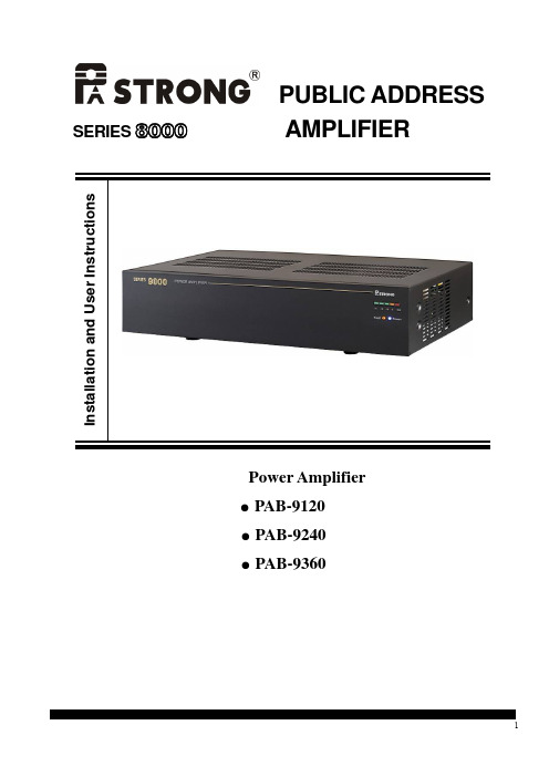
PUBLIC ADDRESS SERIES 8000AMPLIFIERI n s t a l l a t i o n a n d U s e r I n s t r u c t i o n sPower Amplifier●PAB-9120●PAB-9240●PAB-9360IMPORTANTBefore installing or operating this product,please always read this manual carefully.WARNING:To prevent the risk of fire or electric shock,never expose this product to rain or humidity.Table of contentsImportant safeguards-------------------------------------------------------------------------------------2Table of contents------------------------------------------------------------------------------------------21.Introduction------------------------------------------------------------------------------------------------32.Features----------------------------------------------------------------------------------------------------33.Front Panel------------------------------------------------------------------------------------------------34.Rear Panel-------------------------------------------------------------------------------------------------45.Installation-------------------------------------------------------------------------------------------------56.Specification----------------------------------------------------------------------------------------------8IntroductionPAB-9120/9240/9360is a power amplifier series.The output power are120W,240W and360W for wide range purpose. Once there is defective,it will be indicated at the front panel.Dry contact will short to trigger external system when the fault is detected in the amplifier or installation system.0-8Ω-70V-100V different level output for different speaker system.24V battery back up power source will operate when the AC power source is off.Featuresz It has20KHz built-in detecting circuit,which is used to detect whether the unit works normally or not.z It has100V input terminal.It can apply to long distance extension network installation.z It has balanced XLR input terminal and unbalanced RCA input terminal.z The unit could be triggered by remote control terminal.z It has0-8Ω-70V-100V output terminal for different output voltage and impedance.Front Panel:1.Power LEDWhen it is power ON,the blue LED will light up.2.Fault LEDSet the built-in20KHz detect switch at“ON”.If there is no20KHz signal output,over heat,short circuit,the Fault LED will light up.Set the built-in20KHz detect switch at“OFF”will not detect20KHz in the system.The Fault LED will not light up.3.LED VU Meter.VU meter to indicate output signal level.Rear Panel4.AC Line Voltage Selector.Set the slide switch to select AC line voltage(115V or230V AC).Note:Never set the switch to wrong AC Line voltage,it will cause damage to the unit.5.Power SwitchPress rocker switch to switch on the unit.Press again to switch off the unit.6.AC Inlet SocketTo plug in AC power cord.7.AC Line Fuse BracketInsert fuse to the fuse bracket to provide protection for over current.Note:Always use fuse with correct current and voltage rating.8.Chassis GroundA Chassis Ground should be connected during installation9.DC24V Input TerminalInput terminal to connect DC24V power sourceNote:Never connect to the wrong polarity of DC power source.10.Output TerminalsAmplifier output terminals with0-8Ω-70V-100V for different output voltage level and impedances.11.Dry Contact Control TerminalDry contact will close when the unit is damaged or no output.12.Power Remote ON/OFF TerminalRemote control the unit to power ON when the unit is under power switch OFF state.Short Remote Power ON/OFF terminal,the unit will be switched to power“ON”.If the unit is switched to power“ON”state,this Remote Power ON/OFF terminal can not control the unit.When the unit is operated by DC source,it can not be controlled by Remote Power terminal.13.Loop Through RCA Unbalanced OutputRCA terminal for unbalanced input loop through signal to pass the input signal to other amplifiers.14.Loop through XLR Balanced OutputLoop through XLR balanced output terminal.15.XLR Balanced InputXLR socket for balanced input signal.1Vrms,balanced,XLR input.16.RCA Unbalanced Signal InputRCA unbalanced signal input is in parallel to XLR balanced input.The signal level is1V,10KΩunbalanced.17.Input Signal Level TrimmerTo adjust the input level of input signal.18.0-100VFor100V signal input.19.20KHz ON/OFF SwitchSet it at“ON”,pilot tone detect function is ON.Set it at“OFF”,the pilot tone detect function will be off.3.Installation3.1.Unpack packing boxOpen the package box and take out the unit.Please check the accessories and read manual before operate the unit.3.2.(optional)Install unit in rack.The PAB-9120/9240/9360is designed for table top use.If user wants to use in the rack,please screw on rack mounting bracket.Please refer to the drawing.3.3.Set correct AC line in voltageRefer to the AC line in voltage select switch(4)Set the slide switch3.4.Plug in ACPlug the AC powerBefore switch on the unit,please confirm all the installation system is properly connected. 4Connections and settings4.1.Balanced/unbalanced signal inputThere are two types of input:One is balanced signal,the other is unbalanced.It is convenient for connecting the signal from external music source or preamplifiers.4.2.100V input100V input can be connected to amplifier’s output.It is suitable for long distance network.4.3.Adjust input signal levelTurn the input trimmer.(17)to adjust input level.4.4.Loop through outputThe input signal is loop through to output XLR and RCA terminal.It can be connected to next amplifier.4.5.20KHz ON/OFF20KHz is a pilot tone signal.By the detecting of20KHz in installation system,we can judge the system is working properly or not.Set the switch at“ON”,the built-in20KHz detecting system will work to judge the operation of the system.If there is not20KHz,the fault LED will light up,and dry contact terminal(10)will be activated.Set the switch at“OFF”,the built-in20KHz detecting system will not work.4.6.Power remote controlSwitch off the Power Switch,the unit is off.With external switch closed,the unit can be powered on and operate.4.7.Speaker connectionThere is output terminal with 0-8Ω-70V-100V for different purpose andload.Please pay attention to the total equivalent impedance should not be lower than the rated load impedance.4.8.DC batteryThe DC batteries 24V is a back up power source.When the AC power source is off,the DC 24V will take over and let the unit to continue to work.PAB-9120/9240/9360Power Amplifier Specifications Model No.PAB-9120PAB-9240PAB-9360Power Source 115/230V AC,50/60Hz,24V DCRated Output 120W 240W 360W Amp Type Analog Analog Analog Power Consumption 360W 720W 1080W Frequency Response 50-20KHZ +1/-3dBDistortion <1%under rated output powerInput Balanced LINE IN:1V,balancedXLR terminalUnbalanced LINE IN:1V,10K Ω,unbalancedRCA terminal100V Input 100V,balanced inputOutput Unbalanced loop through:1V,unbalanced,RCA Jack outputBalanced loop through:1V,balanced,XLR Jack outputOutput:100V-70V-8Ω-0.S/N Ratio>85dBControl Input Remote Power:Dry Contact terminalOpen Voltage:24V DC(when the unit’s power is OFF),Short circuit toswitch ON the unit.Dry Contact:Open:during normal operationShort:when unit is abnormalIndicator Output level meter:5LEDPower indicator:1LED(Blue) Fault indicator:1LED(Amber)Control Sen.VR to adjust input signal level20KHz Slide Switch:ON/OFF20KHz pilot toneOperating Temperature:-10~45℃Dimension(H×W×D):88×430×300mm88×430×300mm88×430×385mm Weight:Approx10.0kg Approx13.0kg Approx20.0kgMounting(optional)Table Top or19"RackMountableTable Top or19"RackMountableTable Top or19"RackMountable*0dB=1V*-20dB=0.1V*-60dB=1mVz Load:PAB-9120:83ΩPAB-9240:42ΩPAB-9360:28ΩNote:The specification and design are subject to change without notice for improvement. Once fault protection LED light up,the unit will stop operation until faulty issue is solved.。
5W 单声道高保真 D 类音频功率放大器 PA8157 产品手册说明书

PA8157是一款高保真、高效率、低EMI、免滤波、5W单声道D类音频功率放大器。
PA8157内部集成智能增益控制(AGC)功能,通过检测输出信号的大小智能调整系统的增益,避免了过载对于扬声器的损害,防止了音量过大时破音,提高了听觉体验。
PA8157采用了全差分免滤波PWM调制的系统架构,具有较好的抗干扰能力。
其内部集成的过温保护、欠压保护、过流保护、“咔哒”杂音抑制等功能模块,给PA8157提供了更强壮的鲁棒性,使其拥有了更好的适应能力。
PA8157采用了典型的SOP_8封装。
图1.典型应用图应用蓝牙音箱便携式音响设备玩具特点免滤波D类集成(自动增益控制)AGC功能输出功率5W@2Ω(THD+N=10%,5.3V)工作电压域:2.5V~5.5V低失真THD+N=0.04%@1W,5VPOP声抑制效率最高达88%高PSRR=75dB@217Hz过流、过温、欠压保护全差分/单端输入低噪声70μVrms(GAIN=10V/V)失调电压<20mV静态电流6mA@5V关断电流<0.1μASOP_8封装图2.PA8157封装图管脚定义极限参数注1注1:超出以上所列极限参数,可能造成器件的永久损坏。
以上给出的仅是极限范围,在这样的极限条件下工作,器件的技术指标不予保证。
长期在极限条件下工作,会影响器件可靠性。
R IN=10KΩ,C IN=100nF,T A=25℃,VDD=3.8V,除非有特殊说明图3.谐波失真+噪声 Vs. 输出功率图4.谐波失真+噪声 Vs. 频率图5. 输出功率 Vs. 输入幅度图6. 增益 Vs. 频率图7. 效率 Vs. 输出功率图8. AGC触发时间图9. AGC释放时间图10. PA8157测试原理图PA8157为脉冲输出方式,如图9所示,需要在两个输出各接一个低通滤波器将开关调制频率滤除,然后测量滤波器的差分输出即可得到模拟输出信号,VOP和VON被低通过滤后的差分输出波形和相减后的波形如下图所示。
PA6002广带RF线性功率放大器用户说明书

The PA6002 Wideband RF Linear Power Amplifier is highly reliable and suitable for all applications where its output power of 10 watts (15 watts) and wide frequency range (9 kHz to 230 MHz) suit the needs of the test engineer. Able to withstand even high VSWR, the PA6002 is a perfect companion in any radiated and conducted measurement chain: on the product designer’s workbench, in the EMC test laboratory, for in-situ testing, etc.The PA6002 Class A Linear Solid-State Amplifier features a compact and rugged construction, and its MOSFET technology provides high gain, low distortion, consistent performance and high reliability all across the wide frequency band. An analog meter makes it possible to monitor output signal amplitude at a glance, and an alarm LED provides a useful indication when current or temperature levels are outside specifications.The power amplifier can be used with any EMI signal generator, power sensor, CND, EM clamp, current injections clamp and directional coupler for all conducted and radiated, civilian, military and automotive measurements .The complimentary PMM Immunity Suite software delivered with the PA6002 can be used on any PC to automatically perform simple yet complete and effective tests, as it manages all the measurement settings and functions required by the chosen immunity standard .Wideband RF Linear Power AmplifierMain Features•Meets civilian and military standards (e.g. IEC/EN 61000-4-3; IEC/EN 61000-4-6; ISO 11452-4; MIL-STD-461G; etc.)•Suitable for conducted, radiated and automotive immunity tests •9 kHz to 230 MHz frequency range•10 W power output (15 W from 150 kHz to 80 MHz) •40 dB power gain•Class A linear solid-state amplifier •50 Ω input/output impedance • Analog meter and LED indicators • Fan air cooling•Robust and compact constructionOrdering information:PA6002 Wideband RF Linear Power AmplifierIncludes: Power supply cable, BNC-BNC cable, N-m to BNC-f adapter, user’s manual, standard calibration certificateOptional accessories:3010 EMI Signal Generator 9 kHz to 1 GHz3030-01 EMI Signal Generator 9 kHz to 3 GHz, AC supply3030-02 EMI Signal Generator 9 kHz to 3 GHz, AC supply, internal rechargeable battery 6630 USB RF Power Sensor 9 kHz to 3 GHz 6630 FOA Fiber Opic AdapterEP-600 Field probe 100 kHz to 9,25 GHz 0,14 to 140 V/m EP-601 Field probe 10 kHz to 9,25 GHz 0,5 to 500 V/m EP-602 Field probe 5 kHz to 9,25 GHz 1,5 to 1500 V/m EP-603 Field probe 300 kHz to 18 GHz 0,17 to 170 V/m EP-604 Field probe 300 kHz to 26,5 GHz 0,4 to 800 V/m OR03 Optical Programmable Repeater and its probes SB-10 Switching control boxEM Clamps, Current injections clamps, Directional couplers, CDN for mains, Unshielded/ Unbalanced lines CDNs, Shielded lines CDNs, Balanced lines CDNs, 6 dB attenuators, CDN calibration kit and accessories ; for full list and configurations please refer to COND-IS and RAD-IS system documentationGenerators/Receivers/SystemsAntennas/Calibration servicesLISNs/Probes• 1008: Magnetic field generator system • 7010/00: EMI Receiver 150 kHz to 1 GHz • 7010/01: EMI Receiver 9 kHz to 1 GHz • 7010/02: EMI Receiver 9 kHz to 30 MHz • 7010/03: EMI Receiver 9 kHz to 3 GHz • 9010: EMI Receiver 10 Hz to 30 MHz • 9010F: EMI Receiver 10 Hz to 30 MHz• 9010/03P: EMI Receiver 10 Hz to 300 MHz • 9010/30P: EMI Receiver 10 Hz to 3 GHz • 9010/60P: EMI Receiver 10 Hz to 6 GHz • 9030: EMI Receiver 30 MHz to 3 GHz • 9060: EMI Receiver 30 MHz to 6 GHz • 9180: EMI Receiver 6 GHz to 18 GHz • FR4003: Field Receiver 9 KHz to 30 MHz • COND-IS: RF Conducted Immunity System • RAD-IS: RF Radiated Immunity System •AUT-IS: Automotive Immunity System• BC-01: Biconical Antenna 30 to 200 MHz• DR-01: Double-ridged horn Antenna 6 to 18 GHz • LP-02: Log Periodic Antenna 200 MHz to 3 GHz • LP-03: Log Periodic Antenna 800 MHz to 6 GHz • LP-04: Log Periodic Antenna 200 MHz to 6 GHz • TR-01: 60-180 cm wooden extendable tripod• VDH-01: Van der Hoofden Test Head 20 kHz to 10 MHz • Antenna Set AS-02 (BC01+LP02+TR01)• Antenna Set AS-03 (BC01+LP02+LP03+TR01) • Antenna Set AS-04 (BC01+LP04+TR01)• Antenna Set AS-05 (BC01+LP04+DR01+TR01)• RA-01: Rod Antenna 9 kHz to 30 MHz• RA-01-HV: Rod Antenna 150 kHz to 30 MHz • RA-01-MIL: Rod Antenna 9 kHz to 30 MHz • Ansi 63,5 Antenna Factor • SAE ARP 958-D• Free-Space Antenna Factor• CAL-6630: Traceable calibration •LAT-6630: Accredited calibration• L2-16B: single phase AMN, 16 A • L3-32: 4 lines, 3-phase AMN, 32 A • L3-64: 4 lines, 3-phase AMN, 63 A• L3-64/690V: 4 lines, 3-phase AMN, 63 A • L3-100: 4 lines, 3-phase AMN, 100 A• L1-150M: single-path, 50 Ohm AMN, 150 A • L1-150M1: single-path, 50 Ohm AMN, 150 A • L1-500: single phase AMN, 500 A • L3-500: 4 lines, 3-phase AMN, 500 A • L2-D: Delta LISN for telecom, 2 A, 150 Ω• RF-300: Van Veen Loop • SBRF4: RF Switching Box• SHC-1/1000: Voltage probe, 1000 Vac, 35 dB • SHC-2/1000: Voltage probe, 1000 Vac, 30 dBRelated products and servicesP A 6002-F E N -70501 - S p e c i fi c a t i o n s s u b j e c t t o c h a n g e w i t h o u t n o t i c eHeadquarters:Via Benessea, 29/B17035 Cisano sul Neva (SV) - ITALY Phone: +39 0182 58641Fax: +39 0182 586400E-Mail:***********************Internet: www.narda-sts.itSales:Via Leonardo da Vinci, 21/2320090 Segrate (Milano) - ITALY Phone: +39 02 2699871Fax: +39 02 26998700PA6002Wideband RF Linear Power AmplifierSPECIFICATIONSFrequency range Power output CW Power gain Gain flatness Drive levelInput return loss Harmonic distortion RF input RF outputPower indication LED indicators Power supplyOperating temperature Operating humidity Storage temperature Dimensions (W x H x D)Weight9 kHz to 230 MHz10 W; 15 W from 150 kHz to 80 MHz 40 dB+1 dB -1,5 dB0 dBm (1 mW) for 10 W output < 20 dB < -20 dBcZin 50 Ω, BNC female Zin 50 Ω, N female Analog meter, 20 W f.s.Power/current limiter and temperature alarm85 to 264 Vac 47 to 440 Hz / 120 to 370 Vdc 60W 0 °C to +40 °C0 to 90% RH (without condensation)-40 °C to +70 °C 235 x 105 x 300 mm 4,5 kgTypical gain @ nominal power (dB)Power output @ 1 dBc (W)。
PA中文说明书

ALLEN&HEATH PA系列使用手册PA系列混音器可提供一个标准的PA系统需要的所有音频信号处理工具,并使您的操控能够做到“随心所欲”。
您不仅很快就会熟悉并得心应手的操控他们,而且您还会发现他们所具备的许多创新的性能充分融合了设计师多年的现场调音经验。
如果您再仔细地检查一下他们的质量,您就更会欣赏他们标准化的结构:与我们的旗舰产品ML系列调音台有同样的单独的垂直型电路板,同样的电位器帽,同样的铜质内部耦合界面。
下面的几款PA调音台是带有双功率放大器的型号。
PA12-CP有8路单声道和2路立体声通道输入。
PA20-CP有16路单声道和两路立体声输入。
这两款在侧面均有保护装饰,在前面有便携手提把手。
双功放的配置可以根据现场扩音情况的不同来自由的使用。
例如,您可以用其来做没有返送系统的立体声主扩系统,或是有返送和单声道的系统,再或是与外部功放相连,用这台设备做两个独立的返送系统。
同时也可使用额外的单声道输出用于超低音的信号通道等等。
PA-CP系列的功率放大器是第三代的设计,其在出场之前都是已经做了严格的可靠性和声音质量的测试,其输出功率采用4Ω和8Ωohms可切换式恒定功率设计,功率均为2x500W/8Ω。
精准的均衡调节为音乐的创作和有效的抑制房间声反馈提供很大的方便。
所有输出通道都有四段的参量均衡,每个频段均设置有扫频旋钮,我们是通过理论的分析和实际存在的声染色等问题研究和测试以后,决定设置参量均衡,而不用图示均衡的。
并且我们的“EQ Visualiser”软件将会告诉您参量均衡对频率产生的作用,并可以通过此软件与调音台的MIDI口连接来自定义您所需要的效果。
快速启动1.确保安全:首先要确认设备的工作电压与您当地的供电电压是否一致,检查后面板的ON/OFF是否置于off的状态。
用随机配送的电源线将调音台与电源插座相连接。
在没有检查好所有的连线和控制设置之前不要打开任何开关。
并且要确保在前面和侧面机身的通风口处不要有东西挡住。
DSPPA广播系统说明书

【(1)、投标综合说明】DSPPA公共广播系统设备一、公共广播系统概述二、DSPPA 公共广播系统器材性能介绍三、厂区的公共广播/背景音乐示意四、厂区的公共广播/背景音乐示意一、公共广播系统概述DSPPA 广播音响系统涉及面很广,从工厂、学校、宾馆、车站、码头、广场 到会场、影剧院、体育馆、住宅小区等无不与之有密切关系。
在民用建筑工程设计中,广播系统可分为以下几类: 面向公众区(广场、车站、码头、商场、餐厅、走廊、教室等)和停车场等的公共广播系统。
这种系统主要用于语音广播,因此清晰度是首要的。
而且,这种系统往往平时进行背景音乐广播,在出现灾害或紧急情况时,又可转换为紧急广播。
面向宾馆客房的广播音响系统。
这种系统包括客房音响广播和紧急广播,常由设在客房中的床头柜放送,客房广播含有多个可供自Public Address System公 共 广 播 系 统由选择的波段,在紧急广播时,客房广播即自动中断,自动切换为紧急广播。
以礼堂、剧场、体育馆为代表的厅堂扩声系统。
这是专业性较强的扩声系统,它不仅要考虑电声技术问题,还要涉及建筑声学问题。
两者都要统筹兼顾,不可偏废,这类广播系统往往有综合性多用途的要求,不仅可供会场语言扩声使用,还常用于文艺演出等,对于大型现场演出的音响系统,电功率少则几万,多的达数十万瓦,故要用大功率的扬声器和功率放大器,在系统的配置和器材选用方面有一定的要求,同时应注意电力线路的负荷问题。
面向会议室、报告厅等的广播音响系统。
这类系统一般也是设置成公共广播提供的背景音乐和紧急广播两用的系统,但因其特殊性故也常在会议室和报告厅单独设置会议广播系统。
对要求较高或国际会议厅,还需另行设计诸如同声传译系统,会议表决系统以及大屏幕投影电视等的专用视听系统。
从上面介绍可知,对于各种大楼、宾馆及其他民用建筑物的广播音响系统,基本上可以归纳为三种类型:一是公共广播系统(Public Address System简称PA),这种是有线广播系统,它包括背景音乐和紧急广播功能,通常结合在一起,平时播放背景音乐或其他节目,出现火灾等紧急事故时,转换为报警广播。
广播系统-PA

一键 取消 功能
外部 音源 接入
可接入外部 音源设备, 在其它音源 播出时,背 景音乐自动 停止
在车站广播控制终端失效时, 利用广播控制台可以进行广 播操作,实现上述各种广播 功能
后备 模式
紧急 广播 功能
当车站广播控制单元内选区广播模 块发生故障时,按下紧急广播按键, 将车站广播控制台的音频通过应急 通道直接送与功放,此时打开全部 广播区,进行全区广播
控制功能一键取消功能编组功能监听功能背景音乐功能话筒广播功能故障显示功能2020513分区管理功能显示占用功能监听功能显示功能功能图标显示人员操作指示选区选择图标广播区分布电子地图各级广播占用指示选区占用的指示权限内管辖广播选区进行选择监听监听音量可调202051310广播分区占用显示功能广播分区管理监听功能外部音源接入紧急广播功能后备模式一键取消功能led显示灯显广播区选择在车站广播控制终端失效时利用广播控制台可以进行广播操作实现上述各种广播功能当车站广播控制单元内选区广播模块发生故障时按下紧急广播按键将车站广播控制台的音频通过应急通道直接送与功放此时打开全部广播区进行全区广播可接入外部音源设备在其它音源播出时背景音乐自动停止权限内管辖广播选区进行选择监听监听音量可广播区占用指示当车站广播控制台误播一键取消键可立即切断正在进行的广播202051311广播控制台操作功能广播分区管理占用显示显示功能广播选区管理后备模式显示功能广播选区占用背景音乐功能202051312tg200a功放车站控制单元tg200az功放噪声输入单元qh112切换分tg200a功放工控机电源时序控制202051313tg200a前面板图tg200a后面板图202051314tg200a功率放大器的功能
2019/4/8
24
栅格吊顶扬声器
DSPPA广播系统说明书
【(1)、投标综合说明】DSPPA公共广播系统设备一、公共广播系统概述二、DSPPA 公共广播系统器材性能介绍三、厂区的公共广播/背景音乐示意四、厂区的公共广播/背景音乐示意一、公共广播系统概述DSPPA 广播音响系统涉及面很广,从工厂、学校、宾馆、车站、码头、广场 到会场、影剧院、体育馆、住宅小区等无不与之有密切关系。
在民用建筑工程设计中,广播系统可分为以下几类: 面向公众区(广场、车站、码头、商场、餐厅、走廊、教室等)和停车场等的公共广播系统。
这种系统主要用于语音广播,因此清晰度是首要的。
而且,这种系统往往平时进行背景音乐广播,在出现灾害或紧急情况时,又可转换为紧急广播。
面向宾馆客房的广播音响系统。
这种系统包括客房音响广播和紧急广播,常由设在客房中的床头柜放送,客房广播含有多个可供自Public Address System公 共 广 播 系 统由选择的波段,在紧急广播时,客房广播即自动中断,自动切换为紧急广播。
以礼堂、剧场、体育馆为代表的厅堂扩声系统。
这是专业性较强的扩声系统,它不仅要考虑电声技术问题,还要涉及建筑声学问题。
两者都要统筹兼顾,不可偏废,这类广播系统往往有综合性多用途的要求,不仅可供会场语言扩声使用,还常用于文艺演出等,对于大型现场演出的音响系统,电功率少则几万,多的达数十万瓦,故要用大功率的扬声器和功率放大器,在系统的配置和器材选用方面有一定的要求,同时应注意电力线路的负荷问题。
面向会议室、报告厅等的广播音响系统。
这类系统一般也是设置成公共广播提供的背景音乐和紧急广播两用的系统,但因其特殊性故也常在会议室和报告厅单独设置会议广播系统。
对要求较高或国际会议厅,还需另行设计诸如同声传译系统,会议表决系统以及大屏幕投影电视等的专用视听系统。
从上面介绍可知,对于各种大楼、宾馆及其他民用建筑物的广播音响系统,基本上可以归纳为三种类型:一是公共广播系统(Public Address System简称PA),这种是有线广播系统,它包括背景音乐和紧急广播功能,通常结合在一起,平时播放背景音乐或其他节目,出现火灾等紧急事故时,转换为报警广播。
奥拉斯声商业扬声器放大器PA40G PA60G说明书

Specifications are subject to change without notice.PA40G / PA60GCommercial AmplifiersPA40G / PA60G Commercial AmplifiersPA40G Front Silkscreen Artwork Left InRight In1601 Jack McKay Blvd Ennis, TX 75119800.876.333360 Watts 70.7V/100V Speaker OutPA40G / PA60GCommercial Amplifiers1601 Jack McKay Blvd. • Ennis, Texas 75119 U.S.A.Telephone: 800.876.3333 • Fax: 800.765.3435Table of ContentsImportant Safety Instructions (3)Introduction (5)Key Features (5)Applications ............................................................................................................................................ 5 Front Panel Description ...........................................................................................................................6 Rear Panel Description ............................................................................................................................7 Wiring the PA40G / PA60G ......................................................................................................................7 Optional Level Control Security Cover ....................................................................................................8 Optional Rack Mount Kit . (8)Limit LED & Load Considerations (8)Specifications ........................................................................................................................................10 Warranty (12)– 3 –Specifications are subject to change without notice.PA40G / PA60GCommercial Amplifiers1601 Jack McKay Blvd. • Ennis, Texas 75119 U.S.A.Telephone: 800.876.3333 • Fax: 800.765.3435Important Safety Instructions1.Read these instructions.2. Keep these instructions.3.Heed all warnings.4. Follow all instructions.5. Do not use this apparatus near water.6. Clean only with dry cloth.7. Do not block any ventilation openings. Install in accordance with the manufacturer’s instructions.8. Do not install near any heat sources such as radiators, heat registers, stoves, or other apparatus (including amplifiers) that produce heat.9. Do not defeat the safety purpose of the polarized or grounding-type plug. A polarized plug has two blades with one wider than the other. A grounding type plug has two blades and a third grounding prong. The wide blade or the third prong are provided for your safety. If the provided plug does not fit into your outlet, consult an electrician for replacement of the obsolete outlet.10. Protect the power cord from being walked on or pinched particularly at plugs, convenience receptacles, and the point where they exit from the apparatus.11. Only use attachments/accessories specified by the manufacturer.12. Use only with the cart, stand, tripod, bracket, or table specified by the manufacturer, or sold with the apparatus. When a cart is used use caution when moving the cart/apparatus combination to avoid injury from tip-over.13. Unplug this apparatus during lightning storms or when unused for long periods of time.14. Refer all servicing to qualified service personnel. Servicing is required when the apparatus has been damaged in any way, such as power-supply cord or plug is damaged, liquid has been spilled or objects have fallen into the apparatus, the apparatus has been exposed to rain or moisture, does not operate normally, or has been dropped.15. WARNING: To reduce the risk of fire or electric shock, this apparatus should not be exposed to rain or moisture and objects filled with liquids, such as vases, should not be placed on this apparatus.16. To completely disconnect this equipment from the mains, disconnect the power supply cord plug from the receptacle.17. The mains plug of the power supply cord shall remain readily operable.The lightning flash with arrowhead symbol within an equilateral triangle, is intended to alert the user to the presence of uninsulated “dangerous voltage “ within the product’s enclosure that may be of sufficient magnitude to constitute a risk of electric shock to persons.The exclamation point within an equilateral triangle is intended to alert the user to the presence of important operating and maintenance (servicing) instructions in theliterature accompanying the product.– 4 –PA40G / PA60GCommercial Amplifiers1601 Jack McKay Blvd. • Ennis, Texas 75119 U.S.A.Telephone: 800.876.3333 • Fax: 800.765.3435When The Device Is In Use• To prevent electric shock, do not remove the product cover as there are high voltage components inside. Refer all servicing to Atlas Sound.• Should any of the following irregularities occur during use, immediately switch off the power, disconnect the power cord from the AC outlet and contact Atlas Sound. Do not to attempt to continue operation with the product as this may cause fire or electric shock: • Smoke or strange smell coming from the unit. • If the product falls or the case is damaged.• If water or any metallic objects falls into the product. • If the power supply cord is damaged in any way. • If the unit is malfunctioning.• Do not insert or drop metallic objects or flammable materials into the ventilation holes of the product's cover, as this may result in electric shock or fire.• Do not place any containers with liquid or metallic objects on the top of the product. If any liquid spills into the unit, fire or electric shock may result.• Never operate this product or touch the power supply cord during an electrical storm, electric shock may result.• Never exceed the power rating on the product when connecting equipment. Fire and/or property damage may result.• Operate the product only with the voltage specified on the unit. Fire and/or electric shock may result if a higher voltage is used.• Do not modify, kink, or cut the power cord. Do not place the power cord in close proximity to heaters and do not place heavy objects on the power cord, including the product itself, doing so may result in fire or electrical shock.• Ensure that the safety ground terminal is connected to a proper ground. Never connect the ground to a gas pipe as a catastrophic disaster may result.• Be sure the installation of the product is stable, avoid slanted surfaces as the product may fall and causeinjury or property damage.When Installing The Product• Plugging in or unplugging the power cord with wet hands may result in electric shock.• Never move the unit with the power cord plugged into the wall, as damage to the power cord may result. • When unplugging the cord from the wall, grasp the plug, NOT the cord.• Never install this product in humid or dusty locations, nor in direct sunlight, near sources of heat, or in areas where sooty smoke or steam are present. Fire and electric shock may result.• Keep all sides of the unit at least 31⁄2" away from objects that may obstruct air flow to prevent the unit's internal temperature rise.When The Product Is In Use• Never place heavy objects on the product, causing it to fall and/or break, resulting in personal injury and property damage. In addition, the product itself may fall and cause injury and property damage.• Contact Atlas Sound for instructions on cleaning the inside of the unit. Large accumulations of dust inside the unit may result in heat buildup and fire.• Ensure that the power supply plug is securely plugged into the wall outlet. Never allow dust to accumulate on the power plug or inside the wall outlet.•When cleaning the unit or the unit is not to be operated for an extended period, unplug the power cord from the wall.CAUTION WARNING CAUTIONSpecifications are subject to change without notice.PA40G / PA60GCommercial Amplifiers1601 Jack McKay Blvd. • Ennis, Texas 75119 U.S.A.Telephone: 800.876.3333 • Fax: 800.765.3435IntroductionCongratulations and thank you for purchasing the Atlas Sound PA40G/PA60G commercial amplifier. This new and innovativeprofessional grade product has been designed from the ground up to include the important features that professional installationpersonnel require to meet or exceed their customer’s expectations. Small and compact, and engineered for reliability, the Atlas Sound PA40G/PA60G will provide years of service and flexibility in today’s background music and paging applications.Key Features• PA40G - 40W into 70.7V/100V • PA60G - 60W into 70.7V/100V • 1 Balanced Line Input• 1 Unbalanced, Summing Line Level Input • Global Power Supply, 100VAC-240VAC ~ 50/60Hz • Optional Level Control Security Cover• Optional Rack Mount KitApplicationsThe Atlas Sound PA40G and PA60G are the perfect choice for distributed business paging, background music (BGM) systems, and small to medium speech privacy systems.– 6 –PA40G / PA60GCommercial Amplifiers1601 Jack McKay Blvd. • Ennis, Texas 75119 U.S.A.Telephone: 800.876.3333 • Fax: 800.765.3435Front PanelThis LED illuminates when the AC Mains is plugged in.2. Limit IndicatorThe LIMIT LED will illuminate when the PA40G/PA60G is in a clipping condition, caused by excessively high input levels or a GAIN control is turned up too high. An occasional flash is OK. Check that the proper signal level is being fed into the inputs and/or turn the input gain down until the LED is no longer illuminated. Refer to Limit LED & Load Conditions for more information.3. Signal IndicatorWhen the signal LED illuminates, this indicates that input signals connected to the amplifier are capable of driving the PA40G/PA60G to full power.4. Input 1 GainInput 1 level control potentiometer varies the amplitude of the signal fed into the amplifier. Turn clockwise to increase and counter-clockwise to decrease the signal level.Right In100V - 240V 50Hz/60Hz 1ABalanced InputSummed InputsPA60G Front Silkscreen ArtworkSpeaker Out– 7 –Specifications are subject to change without notice.1601 Jack McKay Blvd. • Ennis, Texas 75119 U.S.A.Telephone: 800.876.3333 • Fax: 800.765.3435Rear Panel1. Balanced Line InputBalanced line level signals connect to the (+), (–), and (G) terminals. If you are connecting an unbalanced line level input, tie (short) the (G) and (–) terminals together. If transformer isolation is required for Input 1, contact Atlas Sound for details. Note: The Balanced Line Input and the Unbalanced RCA Inputs are electrically isolated from each other and can be used at the same time.2. Unbalanced Stereo RCA InputInput 2 consists of stereo summing inputs, suitable for connection to the output of CD/DVD players, etc. Note: The Balanced Line Input and the Unbalanced RCA Inputs are electrically isolated from each other and can be used at the same time.3. 70.7V / 100V Speaker OutputFor loudspeaker connections, follow the labeling paying special attention to the polarity or proceed to the Limit LED & Load Considerations section. Note: Do not short the terminals together or damage may occur. It is recommended to use class 3 rated, 16-gauge wire or higher for speaker wiring.4. Global IEC AC Mains Power ReceptacleThe PA Models support global power sources from 100V-240V 50/60Hz. The package contains a cord that has an international IED connector to a 120V USA type plug. It may be necessary to replace the removable power cord to meet your AC Mains plug type used in your country. Note: It is not required to change the fuse for the different AC Mains voltages.Wiring the PA40G / PA60GSpeaker Outputs - Use 2 conductor unshielded wire of the appropriate gauge. If you are unsure about this, contact Atlas Sound Tech Support at 1-800-876-3333. Make sure you know how many speakers you need and what tap value you intend to use.It is recommended to use class 3 rated, 16-gauge wire or higher for speaker wiring.Balanced Line Input - 2 conductor with shield for low level signals of 20 - 22-gauge is best. Maintain the proper polarity, + to +, – to – , and shield to ground.Unbalanced Input - Pre-made RCA cables can be purchased from vendors to simplify interconnection to external devices.4123In order to prevent unauthorized operation of the PA40G & PA60G, optional security covers are available which take the place of the front panel knobs. After the PA amplifier has been installed and is operating as desired, grasp the front panel knobs and pull straight out from the front panel. Replace the knobs with security covers, Atlas Sound part number MPVCC-5, available in quantities of 5.Rack Mount Kit OptionsThe PA40G & PA60G can be rack mounted as a single unit or with two units together. To do so a PA702RMK Rack Mount Kit needs to be purchased from Atlas Sound.Limit LED and Load ConsiderationIf the Red Limit LED illuminates, the amplifier has sensed an improper load or the input signal is too high, triggering the protection circuitry. When the load sense Limit circuitry is engaged the amp will operate but at a lower power output. It is highly recommended to discontinue use immediately and correct the fault condition. If you continue to operate with the RED Limit LED on, the second stage of the current sense circuit may engage causing the amp not to pass any signal. To reset the amp turn down the Level controls and turn the power off for 10 seconds.In most situations when the Limit LED is in the illuminated steady state it means the speaker system load to the amp is lower than what the amp is rated. This usually is detected when the system is first set up. Below are a few load conditions to check for if the Limit LED is on.1. Connected to the wrong speaker terminal. Always check the speaker terminal to the type of load you are using. Example: If you are installing a 70V or 100V system make sure the wires are connected to the 70V/100V and common (COM) terminals.2. Too many speakers connected to the amp. This is a very common mistake. If you are using a 60W amp and using the 70V speaker terminals, add up the number of speakers and their wattage selections at the speaker. If they exceed 60W you must retap the speakers or remove the correct amount speaker wattage until the wattage is 60W or less. Example: If you are using a 30W tap you can only connect 2 speakers to the amp. If you are using the 7.5W tap, you can connect 8 speakers. If you have too many speakers on the amp it will load the amp down, causing excessive current demand and will trigger the Limit & Protect circuit.3. Wrong speaker tap selection. It is also common in a 70V or 100V system that one of the speakers are set too low of animpedance (8 ohm) and not a 70V or 100V tap. Note: It only takes one speaker to load the amp down incorrectly.4. Short in system. This is common if the wire is run in metal conduit and the wire got nicked during the wire pull.5. Speaker Level Controls. If an L-pad or stepped attenuator is wired wrong it can also load a system down.Front Panel KnobSecurity CoverFront Panel Knob Security Coveror– 9 –Specifications are subject to change without notice.PA40G / PA60GCommercial Amplifiers1601 Jack McKay Blvd. • Ennis, Texas 75119 U.S.A.Telephone: 800.876.3333 • Fax: 800.765.3435Measuring Speaker LoadsBelow is an Impedance load chart for the PA40G and PA60G. Measure the load impedance prior to connecting the load to theamplifier. The enclosed load chart will provide the information to determine if the load or speaker system impedance is too low for the amplifier’s rating. In every install it is always recommended to measure the load prior to turning the system on to be sure the system is installed correctly.Measuring a Speaker System’s ImpedanceNote: It is important to only use an Audio Impedance Meter and not a conventional Volt/Ohm meter. A true audio frequency impedance meter is essential for reliable installation of background music and paging systems in residences, office buildings and public areas. Avoid costly service calls and amplifier damage by verifying actual speaker system impedance prior to operation. Unlike conventional volt/ohm meters, which measure DC resistance, an Audio Impedance Meter unit utilizes an internal frequency oscillator to measure true impedance. It may also be utilized with 70.7V and 100V speaker line transformers, L-pads and matching impedance volume controls. There are several Audio Impedance meters on the market, if you need to buy one we suggest going to MCM Electronics, Parts Express or search the internet for “Audio Impedance Meter”.Measuring 70.7V or 100V Distributed Speaker SystemsLarge distributed systems typically utilize 70.7V (North America) or 100V (Europe) type system to greatly ease the connection of multiple speakers and facilitate long cable runs. Shown below are speakers connected in parallel with wattage ratings to calculate the overall load of the system. Connecting an Audio Impedance Meter to a speaker arrangement such as this will provide the overall impedance of the system.Using the following formula you can calculate the load impedance from the speaker selected wattage. The accumulative wattage of the speaker system must not exceed the maximum wattage output rating of the amplifier or damage may occur. In this example the measurement for a 70.7V design with three speakers of 15W each. The system impedance would measure close to 111Ω. Formula 70.7V x 70.7V = 4998, 4998 / 45W = 111Ω. The amplifier power requirements would be at least 60W for the system to operate properly. Note: It is always recommended to use a larger amp than needed with power headroom of at least 25%. Calculate the load impedance and compare it to the meter’s audio impedance reading. Note: They will never be the same due to the additional wire impedance, but if they are within 10% of the maximum impedance rating or if the impedance is higher than the maximum rating, proceed connecting the load to the amplifier. If they are not recheck your speaker taps or check for shorts.PA40G & PA60G Max Load ChartSpeaker Selection PA40G PA60G70.7V 125 Ohms 83 Ohms 100V 250 Ohms 166 OhmsPA40G / PA60GCommercial Amplifiers1601 Jack McKay Blvd. • Ennis, Texas 75119 U.S.A.Telephone: 800.876.3333 • Fax: 800.765.3435SpecificationsTypeC ommercial AmplifierSafety Listings TUV UL60065 Standard, CE, Class 3 RatedElectrical SpecificationsPower Output PA40G: *********(125Ω), 40W @100V (250Ω) PA60G: *********(83Ω), 60W @ 100V (166Ω)Front Panel Indicators Power, Limit, Signal Controls Input 1 GainTechnical Data Frequency Response 50Hz - 20kHzThd+N .5% or Less @ 1kHz, Rated Output Sensitivity Line Input 500mv (600Ω)Inputs 2 / 3 RCA 500mv (10k Ω)Output Regulation Less Than 2dB, No Load To Full Load Signal To Noise Ratio Balanced Input = >55dBUnbalanced RCA Summed = >55dBPower Requirements Power Consumption PA40G: Idle: 0.075A, 8W, 27 BTU Average: 0.26A, 24W, 81 BTU Max: 0.8A, 71W, 242 BTU PA60G: Idle: 0.075A, 8W, 27 BTUAverage: 0.41A, 34W, 116 BTUMax: 1.25A, 102W, 348 BTUFuse PA40G: T630mA PA60G: T1AMechanical Dimensions 8.5" x 1.75" x 7.81" (216mm x 45mm x 198mm)Weight PA40G: Net Weight = 2.9lbs. (1.32kg), Shipping Weight = 3.1lbs. (1.4kg)PA60G: Net Weight = 2.9lbs. (1.32kg), Shipping Weight = 3.1lbs. (1.4kg)Note: Average power consumption is based on one third (1/3) of the maximum power rating, 50% duty cycle.PA40G / PA60GCommercial Amplifiers Notes:1601 Jack McKay Blvd. • Ennis, Texas 75119 U.S.A.Telephone: 800.876.3333 • Fax: 800.765.3435Specifications are subject to change without notice.PA40G / PA60G Commercial Amplifiers1601 Jack McKay Blvd. • Ennis, Texas 75119 U.S.A.Telephone: 800.876.3333 • Fax: 800.765.3435Limited WarrantyAll products manufactured by Atlas Sound are warranted to the original dealer/installer, industrial or commercial purchaser to be free from defects in material and workmanship and to be in compliance with our published specifications, if any. This warranty shall extend from the date of purchase for a period of three years on all Atlas Sound products, including SOUNDOLIER brand, and ATLAS SOUND brand products except as follows: one year on electronics and control systems; one year on replacement parts; and one year onMusician Series stands and related accessories. Additionally, fuses and lamps carry no warranty. Atlas Sound will solely at its discretion, replace at no charge or repair free of charge defective parts or products when the product has been applied and used in accordance with our published operation and installation instructions. We will not be responsible for defects caused by improper storage, misuse (including failure to provide reasonable and necessary maintenance), accident, abnormal atmospheres, water immersion, lightning discharge, or malfunctions when products have been modified or operated in excess of rated power, altered, serviced or installed in other than a workman like manner. The original sales invoice should be retained as evidence of purchase under the terms of this warranty. All warranty returns must comply with our returns policy set forth below. When products returned to Atlas Sound do not qualify for repair or replacement under our warranty, repairs may be performed at prevailing costs for material and labor unless there is included with the returned product(s) a written request for an estimate of repair costs before any nonwarranty work is performed. In the event of replacement or upon completion of repairs, return shipment will be made with the transportation charges collect.EXCEPT TO THE EXTENT THAT APPLICABLE LAW PREVENTS THE LIMITATION OF CONSEQUENTIAL DAMAGES FOR PERSONAL INJURY , ATLAS SOUND SHALL NOT BE LIABLE IN TORT OR CONTRACT FOR ANY DIRECT, CONSEQUENTIAL OR INCIDENTALLOSS OR DAMAGE ARISING OUT OF THE INSTALLATION, USE OR INABILITY TO USE THE PRODUCTS. THE ABOVE WARRANTY IS IN LIEU OF ALL OTHER WARRANTIES INCLUDING BUT NOT LIMITED TO WARRANTIES OF MERCHANTABILITY AND FITNESS FORA PARTICULAR PURPOSE.Atlas Sound does not assume, or does it authorize any other person to assume or extend on its behalf, any other warranty, obligation, or liability. This warranty gives you specific legal rights and you may have other rights which vary from state to state.ServiceShould your PA Series amplifier require service, please contact the Atlas Sound warranty department at1-877-689-8055, ext. 277 or to obtain an RA number.Atlas Sound Tech Support can be reached at 1-800-876-3333 or .Visit our website at to see other Atlas products.©2015 Atlas Sound L.P. All rights reserved. Atlas Sound is a trademark of Atlas Sound L.P.All other trademarks are the property of their respective owners. ATS003582 RevE 2/15。
- 1、下载文档前请自行甄别文档内容的完整性,平台不提供额外的编辑、内容补充、找答案等附加服务。
- 2、"仅部分预览"的文档,不可在线预览部分如存在完整性等问题,可反馈申请退款(可完整预览的文档不适用该条件!)。
- 3、如文档侵犯您的权益,请联系客服反馈,我们会尽快为您处理(人工客服工作时间:9:00-18:30)。
OWNER’S MANUAL
Before operating, please read this manual completely.
PA3002
PA4002
PA5002
Public Address
Amplifiers
FEATURES
Transformer isolated 100V, 70V and 4 Ohms speaker outputs.
5 LED indicator for status display.
XLR socket and mm jack for link convenient.
Output circuit shorting protection & display.
Series amplifiers of high output power available.
AMPLIFIER FRONT VIEW
1.AC power switch(1 is power on and
the “power LED” is on )
2.POWER LED indicator
3.CLIP LED indicator (Please reduce
4.the gain to prevent severely clipped
waveforms reaching the loudspeakers) 5.SIGNAL LED indicator (Output level)6.PROT LED indicator (DC or
output circuit shorted indicator) 7.TEMP LED indicator
(high temperature indicator)
8.Volume (input attenuator)
9.Unit’s fan exhaust window
AMPLIFIER REAR VIEW and CONNECTIONS
1.fan intake window
. output
3.4~16 output
4.70V output
5.100V output
6.220V AC fuse
7.XLR input
8. socket input
9. socket link
10.XLR link
11.220VAC power cord
1 23456 7 8
OPERATING PRECAUTIONS
Make sure the AC main voltage is correct and is the same as that printed on the rear of the amplifier. Damage caused by connecting the amplifier to improper AC voltage is not covered by the three-year US warranty.
Make sure the power switch is off before making any input or output connections. It is always a good idea to have the gain controls turned down during power-up to prevent speaker damage if there is a high signal level at the inputs.
CONNECTING INPUTS
Input connections are made via either the 3-pin XLR -type connectors (Figure 1) or mm sockets on the rear side of the amplifier.
CONNECTING OUTPUTS
Load can be connected using banana plugs or spade lugs. A black binding post is considered “COM”, while the three red binding posts are considered “hot”, and the voltage is 38V (different from the model ), 70V , and 100V .
Note:
Never connect the “hot ”terminals together.
When connecting load (speakers ), it is better to use one pair of output terminals only.
If the PROT Led goes on steadily while power has been turned on and signal has been fed, there must be a trouble of output shorted. Please turn the unit off and correct the trouble then turn it on again.
Figure 1 3-pin XLR-type
connectors
SPECIFICATIONS
HTTP:/ DSPPA ACOUSTIC TECHNOLOGY CO., LTD.使用说
明
欢迎惠顾。
使用前请认真阅读本说明书。
PA3002
PA4002
PA5002
公共广播系列
纯后级广播功放
性能特点
100V, 70V 定压输出和4 Ohms 定阻输出(平衡,不接地)。
5 单位LED 显示器,作状态显示。
RCA 插口和 XLR 插口供方便地实现环接。
输出短路保护并示警。
成系列大功率纯后级可供选择。
1 2 3 4 5 6 7 8
前面板
1. 交流电源开关(按下1为电源接通状态且
电源指示灯亮) 2. 电源指示灯
3. 削顶指示灯 (为避免严重削顶 请适当降低增益)
4. 信号指示灯 (输出电平)
5. 保护指示灯 (直流或短路保护 )
6. 温度指示灯(超温指示)
7. 音量控制旋钮
8.
通风散热窗
后面板及连接
1.风扇风口 2.输出公共端 3.4~16 输出 4.70V 输出 5.100V 输出
6.220V 交流保险丝
7. 卡隆输入口 8. 输入插口 9. 环接插口
10.卡隆环接插口 11.220V 交流电源线
操作注意事项
电源电压应确实与本机相符,由电压不符造成的损坏不在保修之列。
所有输入输出连接好以前,不要通电;通电前最好把音量调至最小以防损坏扬声器。
当通电并输入信号後,如果保护指示灯(PROT)点亮,即说明有输出短路故障.应即切断电源,排除故障後重新加电.
输入之连接
所有输入均应连接於机器後面板之卡隆插口(图1)或 mm 插口。
输出之连接
输出端子在後面板,可用香蕉插或铲形插连接。
黑色乃公共端,红色乃热端。
通常应使用“定压”端子输出,此 时各个扬声器应带线间变压器,扬声器的总功率应与功放的额定输出功率相当。
扬声器在近距离配置时也可用“定阻”(4~16Ω)端子输出,相应地此时扬声器的总阻抗应为4~16Ω。
注意:
宜只选用一对输出端子;
任何时候都不应把两个“热端”连接在一起。
图 1 三线卡隆插
性能规格
性能规格如有改变,恕不另行通知。