7.5-02-07-02.2(waves)
PC版Waves7安装说明

【PC 】WavesComple te 7.1.1.6[混音工具安装说明]Waves7效果包终于放出Win dows版本,本站已在32位Wind ows XP SP2、64位Win dows7中测试安装,没有问题,也在32位C ubase 5和64位S onarX1中加载这套效果器,没有问题。
下面介绍一下Waves 7在Wind ows操作系统中的安装方法。
在开始安装之前,需要先卸载您电脑中的旧版本Wav es效果器,以及清理注册表信息和删除一些残留文件。
如果您的电脑中从来没有装过Wav es效果包,则可以跳过这一段,直接看开始安装部分的说明。
要卸载电脑中的旧版本w aves效果器,请点击开始菜单–控制面板–添加或删除程序,在打开的窗口中,找到您已经安装的wav es效果器,如下图:上图中,我们是安装了waves的Merc ury效果包,您的电脑中不一定也装了这个效果包,而且您的电脑中或许装了不止一个w aves效果包,请仔细查找这个窗口中名称开头包含Waves的项目,点击【删除】按钮进行卸载。
卸载过程很简单,只需要一路点击Next或下一步就可以了。
确定所有wa ves效果器都卸载以后,接下来要清除注册表信息。
32位的Wi n XP、Win Vista、Win 7用户,请删除注册表中的HKE Y_LOC AL_MA CHINE\SOFTWA RE\Waves项。
64位的Wi n XP、Win Vista、Win 7用户,请删除注册表中的HKE Y_LOC AL_MA CHINE\SOFTWA RE\Wow6432Node\Waves项。
如果您对系统注册表的操作不是很熟悉,可以点击这里下载我们提供的一键清理文件,文件下载后解压缩会看到如下图所示的两个注册表文件:这两个文件一个用于32位操作系统的,一个是用于64位操作系统的,请根据您的实际操作系统来选择使用哪一个。
waves-效果器全套中英文说对照表
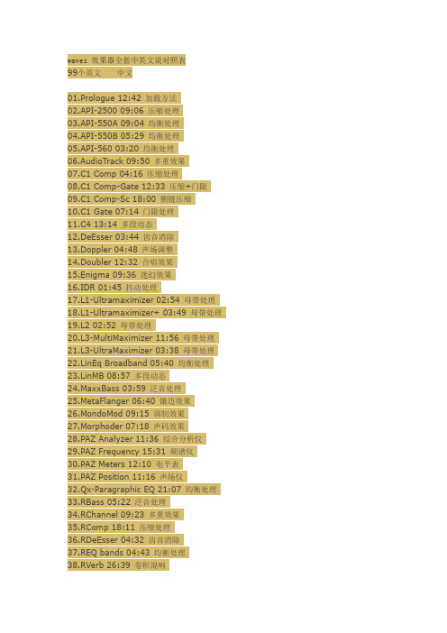
waves 效果器全套中英文说对照表99个英文中文01.Prologue 12:42 加载方法02.API-2500 09:06 压缩处理03.API-550A 09:04 均衡处理04.API-550B 05:29 均衡处理05.API-560 03:20 均衡处理06.AudioTrack 09:50 多重效果07.C1 Comp 04:16 压缩处理08.C1 Comp-Gate 12:33 压缩+门限09.C1 Comp-Sc 18:00 侧链压缩10.C1 Gate 07:14 门限处理11.C4 13:14 多段动态12.DeEsser 03:44 齿音消除13.Doppler 04:48 声场调整14.Doubler 12:32 合唱效果15.Enigma 09:36 迷幻效果16.IDR 01:45 抖动处理17.L1-Ultramaximizer 02:54 母带处理18.L1-Ultramaximizer+ 03:49 母带处理19.L2 02:52 母带处理20.L3-MultiMaximizer 11:56 母带处理21.L3-UltraMaximizer 03:38 母带处理22.LinEq Broadband 05:40 均衡处理23.LinMB 08:57 多段动态24.MaxxBass 03:59 泛音处理25.MetaFlanger 06:40 镶边效果26.MondoMod 09:15 调制效果27.Morphoder 07:18 声码效果28.PAZ Analyzer 11:36 综合分析仪29.PAZ Frequency 15:31 频谱仪30.PAZ Meters 12:10 电平表31.PAZ Position 11:16 声场仪32.Qx-Paragraphic EQ 21:07 均衡处理33.RBass 05:22 泛音处理34.RChannel 09:23 多重效果35.RComp 18:11 压缩处理36.RDeEsser 04:32 齿音消除37.REQ bands 04:43 均衡处理38.RVerb 26:39 卷积混响39.RVox 04:00 压缩处理40.S1-Imager 07:23 立体声扩展41.S1-Shuffler 07:32 立体声扩展42.SoundShifter G Offline 08:11 变速变调43.SoundShifter P 03:26 变调处理44.SoundShifter P Offline 07:11 变速变调45.SSLChannel 36:49 通道条46.SSLComp 06:24 压缩处理47.SSLEQ 07:19 均衡处理48.SuperTap 24:43 延迟处理49.TransX 08:09 瞬间电平控制50.TrueVerb 19:11 模拟混响51.UltraPitch 07:55 自动和声52.X-Click 03:36 去咔哒声53.X-Crackle 03:40 去噼啪声54.X-Hum 06:13 滤波降噪55.X-Noise 10:45 采样降噪56.Z-Noise 12:24 采样降噪57.DeBreath 06:09 去呼吸声58.Tune 01 22:22 音高修正(上)59.Tune 02 16:11 音高修正(中)60.Tune 03 18:07 音高修正(下)AudioTrack是waves的通道条效果器,是一款均衡器/压缩器/门限器的组合C1包括四个,C1comp是单纯的压缩器,C1compgate是压缩/门限的组合,C1SC是旁链压缩器(应用于广播等场合),C1gate是单纯的门限C4是waves的著名多段动态处理器Desser是消除齿音效果器Doppler是掠过音效器,多普勒效应嘛Doubler是声音加倍效果器,做合唱合奏用的Engima是迷幻音效效果器,它利用相位调制原理来产生各种稀奇古怪的效果XIDR是waves自己开发的噪声整型/抖动算法,转换采样深度时用来减小数字背景随机噪声L1/L2/L3都是限制器,区别一个比一个猛,L1可以放在分轨作限制,L2、L3是母带用的。
最完整的waves插件简介及功能简介

最完整的waves插件简介及功能简介名称模拟硬件类别出品其他评星Waves LinEq 否均衡 Waves 母带Eq 延迟很⼤? 4Waves Q-Clone 否均衡 Waves 硬件Eq捕抓器??Waves Q4-Paragraphic Eq 否均衡 Waves 省CPU 5 5Waves Q10-Paragraphic Eq 否均衡 Waves 占⽤10轨CPU资源??Waves REQ 2/4/6 bands 否均衡 Waves 4 4Waves SSL Eq 是均衡 Waves 经典硬件 5 5Waves VEQ 3 是均衡 Waves Vintage ⾳⾊ 5 5Waves VEQ 4 是均衡 Waves Vintage ⾳⾊ 5 5IK Track Equalizer 是均衡 IK TRank 附件PSPaudioware MasterQ 是均衡 PSP 5 4URS BLT EQ 是均衡 URS 界⾯简单 5 4URS FullTec EQ 是均衡 URS 功能全版 5 4URS A Mix EQ 是均衡 URS 5 5URS A Series EQ 是均衡 URS 5 5URS A10 Series EQ 是均衡 URS 5 5URS N Mix EQ 是均衡 URS 5 5URS N Series EQ 是均衡 URS 5 5URS N12 Series EQ 是均衡 URS 5 5URS S Mix EQ 是均衡 URS 5 5URS S Series EQ 是均衡 URS 5 5TC Graphic EQ 是均衡其他经典硬件 5 5TC Parametric EQ 是均衡其他经典硬件 5 5Waves C1 Comp-gate 否压缩 Waves 多段部件噪声门 5 5Waves C4 否压缩 Waves 多段压缩 5 5Waves LinMB 否压缩 Waves 母带压缩多段压缩 5 5Waves MaxxVolume 否压缩 Waves 新⼀代动态处理器 5 5Waves Raxx(获奖)否压缩 Waves Renaissance系列 5 5Waves Rcomp 否压缩 Waves Renaissance系列 4 4Waves Rvox(获奖)否压缩 Waves R系列界⾯简化 5 5Waves SSL Comp 是压缩 Waves 经典硬件 5 5Waves VComp 是压缩 Waves Vintage⾳质 5 5IK Track xCompressor 是压缩 IK TRack附件 5 5PSPaudioware Mastercomp 是压缩 PSP 5 5URS 1970 compressor 是压缩 URS 4 4URS 1975 compressor 是压缩 URS 4 4URS 1980 compressor 是压缩 URS 4 4URS Strip 是压缩 URS 5 4WaveArts MultiDynamics 否压缩 W. Arts 多段压缩 5 4Waves L1-Ultramaximizer 否压限 Waves 5 5Waves L2 否压限 Waves 5 5Waves L3-Ultramaximizer 否压限 Waves 5 5Waves L3-Multimaximizer 否压限 Waves 多段压限 5 5IK Track xClipper 是压限 IK TRack附件 5 5IK Track xLimited 是压限 IK TRack附件多段压限 5 5Wave Arts FinalPlug 否压限 W. Arts 5 4Waves Rchannel(获奖)否综合 Waves 压缩+均衡 5 4Waves SSLChannel 是综合 Waves 压缩+均衡经典硬件 5 5PSP Vintage Warmer 是综合 PSP 多段压缩多段压限 5 5URS 1970 Comp-limited 是综合 URS 压缩+压限 4 4URS 1975 Comp-limited 是综合 URS 压缩+压限 4 4URS 1980 Comp-limited 是综合 URS 压缩+压限 4 4Wave Arts Track Plug 否综合 W. Arts 均衡+压缩+压限 5 5Waves Double 2/4 否延迟 Waves 美化声⾳ 4 5waves supertap2/6taps-mod 否延迟 Waves 5 5Izotope Spectron 否延迟 Izotope 多段延迟经典 5 5Nuendo Double Delay 否延迟 Nuendo 3 2Waves Rverb 否混响 Waves 3 5Waves TrueVerb 否混响 Waves 5 5IK CSR Hall 是混响 IK ⼤厅混响 5 4IK CSR Inverse 是混响 IK 反转混响 5 4IK CSR Plate 是混响 IK ⾦属混响 5 4IK CSR Room 是混响 IK 房间混响 5 4PSPaudioware easyverb 是混响 PSP 操作简单⾳质棒 5 5 Wave Arts MasterVerb 否混响 W. Arts 5 4TC Native Reverb 是混响其他经典硬件省CPU 5 5 Waves IR-L 否采样 Waves 5 4Waves IR-1 否采样 Waves 5 4Wizzo Verb 否采样 Wizzo 5 5Wave Arts Panaroma 否声相 W. Arts 3D 声相场景效果器 5 5 Waves Mondo Mod 否声相 Waves 回旋声相 5 5Waves S1-Shuffler 否声相 Waves 功能完整 5 5Waves S1-Imager 否声相 Waves 功能少点 4 4Waves S1-MS 否声相 Waves 转换⽴体声为MS 4 3PSP PSeudo stereo 否声相 PSP 转换⽴体声 4 4PSP Stereo Controller 是声相 PSP ⽴体声修正 5 4PSP Stereo Enchancer 是声相 PSP ⽴体声拓展 5 4 Waves PAZ Analyzer 否分析 Waves 声相+Freq --Waves PAZ Frequency 否分析 Waves Freq --Waves PAZ Meter 否分析 Waves Output Db --Waves PAZ Position 否分析 Waves 声相--PSP Stereo Analyzer 否分析 PSP 声相+Db --BBE Sonic Maximizer 否激励其他谐波产⽣器 4 5Waves Deeser 否辅助 Waves 消齿⾳ 4 4Waves Debreath 否辅助 Waves 消呼吸声 5 4Waves Rdeeser 否辅助 Waves 消齿⾳ 5 4Waves Doppler 否辅助 Waves 汽车掠过的远近声⾳等 5 4 Waves Morphoder 否⾳效 Waves 噪⾳、合声发⽣器 4 4 Waves SoundShifter 否⾳阶 Waves 4 3Waves UltraPitch 3/6 Voice 否⾳阶 Waves 5 5Waves UltraPitch Shift 否⾳阶 Waves 4 3Waves Enigma 否失真 Waves 迷幻 5 5Waves MetaFlanger 否失真 Waves 镶边 5 5Izotope Trash 否失真 Izotope Best 5 5Waves X-Click 否修复 Waves 噼啪声 5 5Waves X-Crackle 否修复 Waves 爆破⾳ 5 5Waves X-Hum 否修复 Waves 嗡嗡声 5 5Waves X-Noise 否修复 Waves 噪⾳ 5 5Waves Z-Noise 否修复 Waves 噪⾳多段过滤 5 5PSP MixBass 是提升 PSP Bass ? ?PSP MixPressor 是提升 PSP 增强效果 ? ?PSP Mix Saturator 是提升 PSP 饱和效果 ? ?PSP MixTreble 是提升 PSP 多重混合 ? ?Waves MaxxBass 否提升 Waves Bass 4 4Waves MaxxPressor 否提升 Waves 增强效果 4 4Waves MaxxSaturator 否提升 Waves 多重混合 4 4 Waves Rbass 否提升 Waves 提升Bass 均衡 4 4Waves IDR 否技术 Waves 转换精度 16-24bits 5 5。
给大家分享关于Waves效果器各个效果器的中文名称

给大家分享关于Waves效果器各个效果器的中文名称给大家分享关于waves效果器各个效果器的中文名称!px&m3q$p#@\haudiotrackwavesw9p%l#l)l8f多普勒效应传输多普勒2:x2g6z/^(r-odoppler4)engima英格吗迷幻效果器吉他音箱模拟器g#h$g$?8} 9q\idr数码分辨率增加效果器,waves自己开发的噪声整型/抖动算法,转换采样深度时用来减小数字背景随机噪声.y'w1g:b'd'zl1-ultramaximizerl1/l2/l3都是限制器,区别一个比一个猛,l1可以放在分轨作限制,l2、l3是母带用的。
8p8vt1}4xl1-ultramaximizer+L2总线带宽限制器/w@\maxxbass低音增强器-uq2z4x#l\MaxxVolumeSteeo动态处理器!o、 m8s,fqmetaflanger镶变效果器/v9f8_'g)b(`9j4u-b'{mondomod空间回旋效果器Pazanalyzer频谱图形效应器(相位显示/分光计组合)pazfrequency示波器-^2s4[*h4v;G$dpazmeter液位计pazposition相位显示器;a&x-{0^:a!tq1-paragraphiceqq系列都是均衡器,从扫频用的q1到10段的q10,满足各种需要;h$k&o/z\Q10并行IceQ十段均衡器Q2并行IceQ#l3o2c:Q:Wq3-paragraphiceq$y6z6pi:o9il!ustomp2stereo-a\stomp4stereo)n(w7_2b!ustomp6stereo6s&r.m$~9p.cveq4stereo+o.|-?4},}! c:m*p(y9b7kz)c4waves的著名多段动态处理器ir-lefficient空间效果9z*{!{7v)z8t8[$fir-lfull$q\1高效采样混响效应器ir1full3?%y)b8e8x$v2mL3multimaximizer多级总线带宽限制器-n-a6p+t3 | 6g'DL3 UltraMaximizer*]%a7s和C5F3NLINEQ宽带六段均衡器线路QLowBandlinmb2b/b+?.v2c({!gQ4 paragraphiceqq系列均衡器的范围从频率扫描的Q1到10段的Q10,以满足Q6 paragraphiceqq8 paragraphiceqraxx,t(h#o-a)的各种需求\rdeesser文艺复兴插件包里的消除齿音4t7l6v5l8zreq2bands文艺复兴插件包里的均衡器req4bandsreq6bands+}6{.f*t0l&e.y-x&orvox文艺复兴插件包里的人声自动压缩器2s6t0t\s1-imager立体声增强效果器9w8r!a4l(xs1-msmatrixs1 shuffler+o%h:r$a1l\supertap2-tapsmod打点延迟效果器#c0r0h'w/q,`3z%n$`supertap6-tapsmodtrueverb+y$x*r%z$`)v'^0r)s%ph-o/]ultrapitch3-voice人声变调效果器5z#h$i:s4w1`;yultrapitch6-voiceultrapitchshiftX-点击以消除裂纹X-点击以消除裂纹x-hum降低气声1c%\\4p7w+l0_x-noise降噪Morphoder卷积变音效应器。
Waves水星包新年版的安装
所以,让你彻底删除老版本,一个不留,哈哈!
解压
有的朋友下载了软件不知道怎么安装,我在网上也没找到相关的详细说明,下面是我自己的经验与大家分享:
初期下载到电脑上的仅仅是一个压缩文件,把他解压到一个文件夹下,会解压出现70多个文件,大部分也全都是压缩文件,
\Program Files\Waves
\documents and settings\username\userdata/Waves
\documents and settings\username\userdata/Waves Audio
\documents and settings\username\userdata/Waves Preferences
检查
\common files\Digidesign\DAE\Plug-Ins
如果你从来没装过RATS插件的话这步就跳过
\vstPlugins
VST插件文件夹,默认是在C:\Program Files\Steinberg\VstPlugins
删除所有waveshell.dll,以及 *.dpm *.rsr 文件
我们双击它就可以正常进行安装了,安装时候最好是选择默认的目录,因为据有些朋友测试,如果安装到自设位置的话选择变更目录的时候,
会没有“确定”键,很麻烦。
祝dit进入注册表编辑器,然后一层层寻找)
[HKEY_LOCAL_MACHINE\SOFTWARE\Waves]
[HKEY_LOCAL_MACHINE\SOFTWARE\Propellerhead Software\ReWire\WavesReWireDevice]
Waves 系统介绍

Waves 系统介绍雪帝数字音频一、Waves系统工具栏二、预置三、界面控制四、Waves 偏好 (仅支持Pro Tools)一、Waves系统工具栏所有的Waves插件都有WaveSystem工具栏,它可以照顾到你在使用Wave软件时遇到的大多数管理功能。
WaveSystem 工具栏运用于所有的Waves插件,所以熟悉其特性对你使用任意插件都是有帮助的。
工具栏功能W (展示包装)Undo (撤销)撤销最后32步动作。
Redo (重做)恢复撤销最后32步动作。
Setup A/B (设置A/B)在两个预置之间进行切换,方便进行对比。
L/R Arrows (左右箭头)切换前一个或下一个预置。
A→B / B→A (复制A→B / B→A )将当前设置复制到第二个预置寄存器。
Load (加载)调出预置。
Save (保存)保存预置(以Waves文件格式)。
?打开此插件的PDF手册。
二、预置类型出厂预置是加载菜单中的永久预置。
出厂预置不能被重写和删除,不同的插件通常有不同的出厂预置。
用户预置将你的偏好设置保存在加载菜单“User Presets(个人预置)”下。
个人预置可以被改写或删除。
设置文件可能包含不止一个预置。
例如,单个文件可以包含所有的预置。
打开安装文件时,它的所有预置都会成为快捷菜单,以便快速访问。
载入点击载入按键(Load)可以看到下拉菜单。
下拉菜单分为多个部分。
如果某一部分当前不可用,它将不会出现在下拉菜单中。
Open Preset File…(打开文件夹)打开任意设置或预置文件,可能来自设置库或是你的个人库存。
Factory Presets:(出厂预置)弹出出厂预置。
User Presets:(用户设置)弹出所有个人设置。
保存点击保存按钮(save)可以看到下拉菜单,共有四种选择。
如果一个选项当前不可用,则该选项将变为灰色,无法访问。
Save to New File…(新建预置文件)有两个提示-1.输入文件名 2.输入预置名。
WAVES效果器说明书四篇
WAVES效果器说明书四篇篇一:WAVE效果器REVERB的中文说明书第一章- 简介感谢使用Waves Renaissance Reverberator软件。
这个软件是为使用支持DIRECT X专业音频软件的用户设计的。
Renaissance Reverb 软件可以对传统的声音进行极好的控制。
现在市场上有很多处理器用于直接模仿老式乐器的声音。
但是Renaissance Reverb 软件则为用户提供了一个可以创新及灵活应用的、用于模仿老式合成器声音的工具。
我们采用了TrueVerb软件中早期反射声系统作为开始,然后以多种方式对其进行改造,建立一个新的后期混响。
我们同时还建立了一个可视性很强的界面,用于监视反馈信号及调整各项参数。
第二章 - 快速入门基本操作方法对于干湿对比度基本的使用手法是:• 在使用断点插入为一个音轨提供效果时,在调入一个预置方案后,应将湿/干对比度设置成100%。
• 在使用辅助总线为一个音轨提供效果时,在调入一个预置方案后,应将湿/干对比度设置成50%。
使用这个软件的大体过程如下:• 调用一个预置方案。
• 调整用于修饰声音色彩的混响特性。
• 调整混响电平(同早期反射声的比例也随之变化)。
• 调整各均衡参数,对某一频段进行提升或衰减。
• 对各项参数做细微的调整。
在操作界面的最上端,是Waves系列标准的控制模式。
详见“WaveSystem”一章。
该章所涉及的内容在使用所有Waves系列的软件时都会遇到,了解这些控制按钮会为你的操作带来很多方便。
Waves系列软件性能非常出色,它们可以使用户同时控制多个参数。
界面上方的三块图形显示了时间和频率反应特性。
在混响阻尼(Reverb Damping)和混响均衡(Reverb EQ)图形上,只需要简单地拖动图形上的节点,就可以改变混响的阻尼和均衡参数。
在界面的下方有9个推子,这9个推子可分为两类:控制声音的特性和控制音量。
第三章 - 软件的构成使用软件时,用户可以在音频软件的有关编辑菜单中找到plug-in (插件)菜单,然后就可以找到Waves 系列的插件程序。
《Waves V7音频插件合集》 中的部分效果器介绍 一(又下载地址含注册机)
《Waves V7音频插件合集》中的部分效果器介绍一Waves.SSL Channel Stereo 通道控制效果器SSL Comp Stereo 压缩效果器Stereo 均衡效果器SSLEQ他们都有立体声和单声道版本Waves.SSL Channel Stereo 通道效果器Waves SSLChannel Stereo界面大致可以分四个部分Dynamics 动态处理部分这一部分包括:压缩限制调节有三个白色的旋钮和一个白色的开关组成:右侧起1.Threshold 阀值调节Ratio Compress 压缩比率调节Release 释放比率调节F.Atk 起始时间设置开关2.扩展门限效果调节Threshiold 阀值调节它下面有一个GATE 按钮,它是门限按钮Expand 范围调节Release 起始时间调节F.ATK 起始时间设置开关3.Dyn To 动态处理路由设置左侧By Pass是直通按钮,按下它可以对比处理之前与之后的声音右侧的CH OUT 按钮可以处理动态处理的路由,是用来控制均衡器之前和之后的设置4.Filters 滤波控制部分滤波控制分别有:高通滤波调节用来节制低通音频信号只允许高频信号通过,低通滤波调节Split 分离按钮,按下按钮就是要声音先经过滤波器再经过动态处理。
5.四段参数均衡器:1.两个红色的旋钮,是高频调节旋钮作用频点调节和频点增益调节BELL按钮时激活按钮2.三个绿色的旋钮是中高频调节旋钮从右到做是作用频点、频点增益、连续调节的Q值旋钮。
3.三个蓝色旋钮是中低频调节旋钮,作用频点、频点增益、连续调节的Q值旋钮。
用来节制高频音频信号只允许低频信号通过,4.两个黑色旋钮式低频调节旋钮。
最下面的均衡控制和总输出控制部分作用频点、频点增益、BELL Q值切换开关组成中间部分有两个EQ TO 路由均衡设置。
By Pass 为直通开关。
激活它音频信号不受均衡器的影响,可以用它来听均衡处理之前和之后的音响效果。
Waves GEQ用户指南说明书
WAVESGEQ GRAPHIC EQUALIZERUSER GUIDETABLE OF CONTENTSCHAPTER 1 – INTRODUCTION (3)1.1W ELCOME (3)1.2P RODUCT O VERVIEW (3)1.3C ONCEPTS AND T ERMINOLOGY (4)1.4C OMPONENTS (6)CHAPTER 2 – QUICK START GUIDE (7)CHAPTER 3 – INTERFACE AND CONTROLS (9)3.1I NTERFACE (9)3.2C ONTROLS (10)CHAPTER 4 – THE WAVESYSTEM (17)4.1T HE W AVE S YSTEM T OOLBAR (17)4.2P RESET H ANDLING (17)4.3I NTERFACE C ONTROLS (20)4.4W AVES P REFERENCES (P RO T OOLS ONLY) (22)Chapter 1 – Introduction1.1 WelcomeThank you for choosing Waves! In order to get the most out of your Waves plugins, please take the time to read through this manual.In conjunction, we also suggest that you become familiar with . There you will find an extensive Answer Base, the latest Tech Specs, detailed Installation guides, new Software Updates, and current information on Authorization and Registration.By signing up at , you will receive personalized information on your registered products, reminders when updates are available, and information on your authorization status.1.2 Product OverviewWaves GEQ is a full-featured graphic equalizer with both Classic and Modern mono and stereo components, featuring 30 ISO bands plus high and low pass filters, a high precision floating parametric EQ bell filter, and a real-time analyzer.GEQ Classic components use traditional proportional Q filters inspired by the renowned DN series 1/3 octave equalizers, which narrow the filter width as you increase a band’s gain; GEQ Modern components utilize special Flat-Top filters which eliminate the artifacts associated with band interaction, and provide perfect plateau and stair-stepped responses. Set band gains one-by-one, or draw your curve via touch-screen or mouse. Finally, GEQ’s integrated real-time analyzer lets you compare the difference between two sources. Created for live sound but equally useful in the studio as well, GEQ is powerful proof that all equalizers are not created equal.Waves GEQWaves GEQ1.3 Concepts and TerminologyGraphic EQMost graphic equalizers consist of a bank of filters with pre-determined (fixed) cutoff frequencies, typically divided into bands of 1/3 or one octave each, with frequency cutoffs defined by ISO standards (International Organization for Standardization). It’s common to see the gain controls set as a horizontal array of faders with the lowestfrequency on the left and the highest on the right. So if one were to draw a line that plots the gain fader positions at any given time, the resultant line would be a graphicalrepresentation of the equalizer’s current frequency response, hence the name “graphic equalizer.”The GEQ offers three bands per octave for a total of 30 bands, similar to the hardware devices commonly used in live sound reinforcement systems. GEQ includes a faders array as well as parametric graph, plus a real-time analyzer with flexible routing.Proportional QFor its 30 main bands, the GEQ Classic component uses “Proportional Q” filters. The Q value is proportional to the gain adjustment; increasing a band’s gain narrows the filter width.Waves GEQFlat-Top FiltersThe GEQ Modern component utilizes special Flat-Top filters which eliminate the artifacts associated with band interaction, and provide perfect plateau and stair-steppedresponses. Thus, boosting a set of consecutive bands by 6 dB will result in a 6 dB boost plane, without additional boost due to band interaction.Band InteractionClose to 0 dB, Proportional Q bells have a fairly wide frequency range. This is not an issue when boosting or cutting frequencies in different ranges; however, when boosting adjacent bands, the two filters will overlap and interact, resulting in unintended gain levels.Classic Proportional Q Filters Modern Flat-Top Filters1.4 ComponentsWaveShell technology enables us to split Waves processors into smaller plugins, which we call components. Having a choice of components for a particular processor gives you the flexibility to choose the configuration best suited to your material.GEQ has a total of four components:•GEQ Classic Mono•GEQ Classic Stereo•GEQ Modern Mono•GEQ Modern StereoWaves GEQChapter 2 – Quick Start GuideUsing the EQ1. Open a mono or stereo GEQ component on a track.2. Select Drag or Draw mode.3. Drag mode: Select individual band faders, move each up or down to set itsboost/cut.Draw mode: Select a band fader, move up or down and continuously left or right to draw the EQ curve.4. For further adjustments, use the floating Parametric EQ section to set non-ISOfrequency cutoffs.Setting and Calibrating the Analyzer1. Open a mono or stereo GEQ component on an output track.2. On the WaveSystem toolbar, go to RTA1 and select a source. (See Section3.2.)3. On the WaveSystem toolbar, go to RTA2 and select a sidechain input. Forexample, the sidechain input can receive its signal from a microphone whichmeasures the RTA1 source after passing through the PA system:4. On the WaveSystem toolbar, activate Calibration Mode by clicking Calibration.5. Select the RTA Mode: Fast or Slow.6. If required, calculate the delay between the two RTA input sources, and enter thevalue in milliseconds into the RTA1 Delay field.Waves GEQ7. Adjust the RTA1 and RTA2 displayed curve levels using the faders next to theinput and output meters. Please note: Adjusting these faders will affect only the analyzer; it will not affect your output.8. Press Diff to view the difference in frequency response between RTA1 andRTA2.9. Match the two signals manually using the EQ section of the plugin.Waves GEQChapter 3 – Interface and Controls3.1 InterfaceGEQ Classic StereoGEQ Modern StereoWaves GEQWaves GEQ3.2 ControlsAnalyzer SectionGRAPHIC DISPLAY / ANALYZER shows the EQ curve, RTA1 and RTA2 input RMS frequency responses and the Difference between them.Brown EQ curve on mono components; Left channel EQ curve on stereo components. Blue Right channel EQ curveYellow RTA1 input frequency responseCyan RTA2 input frequency responseRed Difference between RTA1 and RTA2Frequency Range: 20 – 20,000 HzLevel Range: -80 – 0 dBFSINPUT METER displays input level (peak) in dBFS.Range: -80 – 0 dBFSOUTPUT METER displays output level (peak) in dBFS.Range: -80 – 0 dBFSRTA1 assigns the first input to the real-time analyzer.RTA2 assigns the second input to the real-time analyzer.Mono Component Range: Off, In, SC-In, OutStereo Component Range: Off, L-In, R-In, LSC-In, RSC-In, L-Out, R-Out, L+RDIFFERENCE mode turns off the real-time analyzer and displays the difference in frequency response between RTA1 and RTA2. This is helpful when you need to:▪Adjust the output signal in relation to the measured post-system response.▪Match the left and right frequency responses.Range: On, OffWaves GEQCalibration ModeCALIBRATION activates the Calibration mode which calibrates the analyzer.RTA1 & RTA2 FADERS are used to adjust and match the analyzer input levels.RTA CALIBRATION set the response time of the analyzer.Please note: When Difference is on, the response is Slow, regardless of the RTA Calibration setting.Range: Fast, SlowRTA1 DELAY sets the alignment of RTA1 to RTA2.Range: 0 – 341 millisecondsWaves GEQGraphic EQ SectionSCALE controls the maximum range of GEQ faders. The scale indicators next to the band faders update according to the selected scale. For example, if the 6 dB scale is selected and 25 Hz is set to +5 dB, changing the scale to 12 dB increases the boost at 25 Hz to +10 dB.Range: 6, 12, 18 dBQ functions as a multiplier for the proportional Q algorithm. (Classic components only) Range 0.250 – 4.000Waves GEQISO FADERS control the gain of selected frequency centers.Gain Range: -18 to +18 (dependent on Scale settings)Frequency Cutoffs: 25 Hz, 31 Hz, 40 Hz, 50 Hz, 63 Hz, 80 Hz, 100 Hz, 125 Hz, 160 Hz, 200 Hz, 250 Hz, 315 Hz, 400 Hz, 500 Hz, 630 Hz, 800 Hz, 1 kHz, 1.25 kHz, 1.6 kHz, 2 kHz, 2.5 kHz, 3.15 kHz, 4 kHz, 5 kHz, 6.3 kHz, 8 kHz, 10 kHz, 12.5 kHz 16 kHz, 20 kHzDRAG selects the method of setting the band faders.▪Drag mode: Select individual band faders; move each up or down to set its boost/cut.▪Draw mode: Select a band fader; move up or down, left or right, continuously, to draw the EQ curve.Range: Drag, DrawLINK relatively links left and right channels, including all bands, high and low pass filters, floating Parametric Bell EQ and Master Gain settings. (Stereo components only) Range: On, OffFLAT snaps all bands to 0 dB.Please note: This does not affect the floating Parametric EQ section.Waves GEQFloating Parametric EQ SectionHP activates the high pass filter.Range: On, OffHP FREQUENCY sets the cutoff frequency of the high pass filter.Range: 20 – 990 HzLP activates the low pass filter.Range: On, OffLP FREQUENCY sets the cutoff frequency of the low pass filter.Range: 1000 – 20,000 HzPARAMETRIC BELL activates the floating parametric bell filter.Range: On, OffPARAMETRIC BELL FREQUENCY sets the cutoff frequency of the floating parametric bell filter.Range 20 – 20,000 HzPARAMETRIC BELL GAIN controls the gain of the floating parametric bell filter. Range: +/- 18 dBWaves GEQPARAMETRIC BELL Q determines the width of the floating parametric bell filter. Range: 0.250-50MASTER GAIN controls the output level of the entire plugin.Range: +/- 18 dBWaves GEQChapter 4 – The WaveSystem4.1 The WaveSystem ToolbarAll Waves plugins feature the WaveSystem toolbar which takes care of most administrative functions you will encounter while working with your Waves software. The features of the WaveSystem toolbar are the same on practically all Waves plugins, so familiarity with its features will be helpful whichever plugin you are using.Toolbar FunctionsOpens the plugin About boxUndo Undoes the last 32 actionsRedo Redoes the last 32 undone actionsSetup A/B Toggles between two presets, useful for comparison of parametersettingsL/R Arrows Move to the previous or next presetCopy A→B Copies the current settings to the second preset registerLoad Recalls presets from fileSave Saves presets in the Waves file formatsOpens the PDF manual for the plugin you are using4.2 Preset HandlingPreset TypesFactory Presets are permanent presets in the Load menu. Factory presets cannot be overwritten or deleted. When applicable, different component plugins may have different factory presets.User Presets are your favorite settings of the plugin saved as a preset in the Load menu, under ‘User Presets’. User Presets can be overwritten and deleted.Waves GEQSetup Files may contain more than one preset. For example, a single file can contain all the presets for a session. When you open a Setup File, all its setups become part of your Load pop-up menu for fast access. This can be particularly useful with multiple instances of a plugin in a single session. By saving all the settings you create into a single Setup File, they can all be quickly available for every instance of that plugin.Loading Presets and SetupsClick on the Load button to see the Load pop-up menu. The menu is divided into four sections. If a section is not currently available it will not appear in the Load pop-up menu.Open Preset File…Select to open any setup or preset file, whether from the Library oryour own creations.‘Filename.xps’: Displays any currently loaded Setup File and its presets.Factory Presets:Displays the default Factory Presets.User Presets:Displays any loaded User Presets.Saving Presets and SetupsClick on the Save button to see the Save pop-up menu. Four options are available. If an option is not currently available it will be grayed out and inaccessible.Save to New File…Select this to start a new Setup file. There are twoprompts - first for the setup filename, then for thepreset name. You must provide a name for both thesetup file and the preset. Click OK (ENTER) tocomplete the save. It is a good idea to create afolder in which to save several setup files for aproject.Save ‘File Name’ – “Preset Name” Overwrites the settings of the loaded preset(whether a User Preset or a preset from a SetupFile) with the current settings. If a Setup File isWaves GEQcurrently loaded, the name of the Setup File isdisplayed followed by the name of the preset itself.If a User Preset is loaded, its name is displayed. Save to ‘File Name’ As…Saves the current settings as a new preset into theSetup file that is open (if one is not open, the optionis grayed out). You will be prompted to give thepreset a name.Put into Preset Menu As…Save the current settings into a User Preset thatwill always be in your Load menu (until deleted).You will be prompted to give this preset a name.User Presets are stored in the plugin’s preferencefile.Deleting PresetsYou may delete User Presets and presets within a Setup File. Factory Presets and Setup Library files cannot be deleted or overwritten.1. Hold the Command (Mac)/Control (PC) key down.2. Click-and-hold the Load button to see the pop-up menu.3. While still holding the Command/Control key, select the preset or setup to delete.4. A confirmation box will appear, allowing you to cancel or ‘OK’ the deletion.A/B Comparison and CopyingThe Setup A/Setup B button may be clicked to compare two settings. If you load a preset in the Setup B position, this will not affect the preset loaded into the Setup A position, and vice-versa.If you want to slightly modify the settings in Setup A, you can copy them to Setup B by clicking on the Copy to B button, then alter Setup A and compare with the original Setup B.Waves GEQThe name of the current setup will be shown in the title bar (on platforms which support it), and will switch as you change from Setup A to Setup B.Note: an asterisk will be added to the preset name when a change is made to the preset.4.3 Interface ControlsControls can be in one of three states:•Not Selected where the control is not the target of any user entry•Selected where the control is the target of mouse control entry only•Selected and Active where the control is the target for both mouse and keyboard entryToggle ButtonsToggle buttons display the state of a control, and allow switching between two or more states. Single-click to change the control’s state. Some toggle buttons have a text display which updates with the current setting, and others (bypass, solo, or monitoring toggles) illuminate when the control is active.Some plugins have link buttons between a pair of toggle buttons, allowing click-and-drag adjustment while retaining the offset between the controls.Value Window ButtonsValue windows display the value of a control and allow click-and-drag adjustment, or direct control via the keyboard.1. Using the mouse, click-and-drag on the value window to adjust. Some valuewindows support left/right, some up/down (as you hover over a button, arrowswill appear to let you know which direction of movement that button supports).You may also use your mouse-wheel to adjust parameter values.2. Using the arrow keys, click once with mouse to select the button, and then useup/down – left/right (depending on the direction supported by that button) toWaves GEQmove in the smallest incremental steps across the button’s range (holding down the arrow keys will move faster through the range).3. Using key entry, double click on the button to open the value window, anddirectly enter the value from your keyboard. If you enter an out of range number, the button stays selected but remains at the current setting. (System beeps ifsystem sounds are on.)Some plugins have link buttons between a pair of value windows, allowing click-and-drag adjustment while retaining the offset between the controls.SlidersClick or scroll the mouse-wheel on the slider itself or anywhere within the sliders track. The numerical value of the slider settings is displayed in a hover window above the slider path.Hover BoxHovering boxes will appear and display the control value when hovering with the mouse over the control.Multiple Control SelectionOne of the most powerful features of the WaveSystem is the ability to select and adjust multiple controls simultaneously. Using the mouse, drag-select the desired group of buttons or graphic controls by clicking and holding at a point outside the controls, and forming a rectangle that includes the controls you wish to adjust. Alternatively, press and hold Shift while clicking the mouse on any control you wish to link. This method is useful when you want to select two or more controls that are not adjacent to one another.Waves GEQTAB FunctionsTAB moves the ‘selected’ status to the next control, with shift-TAB moving in the reverse direction.Additionally, the Mac has an option-TAB function for ‘down’ movement and shift-option-TAB for ‘up’ movement where applicable.If you have several Value Window Buttons selected, TAB functions will take you through the selected controls only.Hitting Esc or Return will return the 'focus' to the DAW application.4.4 Waves Preferences (Pro Tools only)When launching Pro Tools, hold Shift to view the Waves plugin Preferences window. The following options are available:•Don't use AudioSuite plugins•Don’t use RTAS plugins•Rescan all plugins•HUI control surface support (low resolution)•Enable single-click text entryWaves GEQ。
waves 效果器全套中英文说对照表
waves 效果器全套中英文说对照表99个英文中文01.Prologue 12:42 加载方法02.API-2500 09:06 压缩处理03.API-550A 09:04 均衡处理04.API-550B 05:29 均衡处理05.API-560 03:20 均衡处理06.AudioTrack 09:50 多重效果07.C1 Comp 04:16 压缩处理08.C1 Comp-Gate 12:33 压缩+门限09.C1 Comp-Sc 18:00 侧链压缩10.C1 Gate 07:14 门限处理11.C4 13:14 多段动态12.DeEsser 03:44 齿音消除13.Doppler 04:48 声场调整14.Doubler 12:32 合唱效果15.Enigma 09:36 迷幻效果16.IDR 01:45 抖动处理17.L1-Ultramaximizer 02:54 母带处理18.L1-Ultramaximizer+ 03:49 母带处理19.L2 02:52 母带处理20.L3-MultiMaximizer 11:56 母带处理21.L3-UltraMaximizer 03:38 母带处理22.LinEq Broadband 05:40 均衡处理23.LinMB 08:57 多段动态24.MaxxBass 03:59 泛音处理25.MetaFlanger 06:40 镶边效果26.MondoMod 09:15 调制效果27.Morphoder 07:18 声码效果28.PAZ Analyzer 11:36 综合分析仪29.PAZ Frequency 15:31 频谱仪30.PAZ Meters 12:10 电平表31.PAZ Position 11:16 声场仪32.Qx-Paragraphic EQ 21:07 均衡处理33.RBass 05:22 泛音处理34.RChannel 09:23 多重效果35.RComp 18:11 压缩处理36.RDeEsser 04:32 齿音消除37.REQ bands 04:43 均衡处理38.RVerb 26:39 卷积混响39.RVox 04:00 压缩处理40.S1-Imager 07:23 立体声扩展41.S1-Shuffler 07:32 立体声扩展42.SoundShifter G Offline 08:11 变速变调43.SoundShifter P 03:26 变调处理44.SoundShifter P Offline 07:11 变速变调45.SSLChannel 36:49 通道条46.SSLComp 06:24 压缩处理47.SSLEQ 07:19 均衡处理48.SuperTap 24:43 延迟处理49.TransX 08:09 瞬间电平控制50.TrueVerb 19:11 模拟混响51.UltraPitch 07:55 自动和声52.X-Click 03:36 去咔哒声53.X-Crackle 03:40 去噼啪声54.X-Hum 06:13 滤波降噪55.X-Noise 10:45 采样降噪56.Z-Noise 12:24 采样降噪57.DeBreath 06:09 去呼吸声58.Tune 01 22:22 音高修正(上)59.Tune 02 16:11 音高修正(中)60.Tune 03 18:07 音高修正(下)WAVES HELP第一种效果:AudioTrack(音频轨)它是针对通常我们见到的普通的音轨的,综合了4段EQ均衡、压缩、噪声门三种效果器。
- 1、下载文档前请自行甄别文档内容的完整性,平台不提供额外的编辑、内容补充、找答案等附加服务。
- 2、"仅部分预览"的文档,不可在线预览部分如存在完整性等问题,可反馈申请退款(可完整预览的文档不适用该条件!)。
- 3、如文档侵犯您的权益,请联系客服反馈,我们会尽快为您处理(人工客服工作时间:9:00-18:30)。
PREDICTION OF POWER INCREASE INIRREGULAR WAVES FROMMODEL TEST ....................................... 21. PURPOSE OF PROCEDURE .............. 22. INTRODUCTION ................................. 23.SUMMARY OF PREDICTION METHODS ............................................. 43.1 Torque and Revolution Method (QNM) ................................................. 43.2 Thrust and Revolution Method(TNM) ................................................. 43.3 Resistance And Thrust IdentityMethod (RTIM) ................................. 93.4 Self-propulsion test in irregularwaves ................................................. 103.5 Resistance test in irregular waves .. 104. BRIEF DESCRIPTION OF MODEL EXPERIMENTS NECESSARY FOR THE PROCEDURE............................ 10 4.1 Resistance test in regular waves ..... 104.1.1 Procedure in general ................... 104.1.2 The model ................................... 104.1.3 Towing technique ....................... 114.1.4 Test conditions ........................... 114.2 Self-propulsion test in regular waves ........................................................ 114.2.1 Procedure in general ................... 114.2.2 Model preparation ...................... 114.2.3 Testing technique ....................... 114.2.4 Test conditions ........................... 124.3 Tests in irregular waves .................. 125. PARAMETERS TO BE TAKEN INTO ACCOUNT ........................................... 126.VALIDATION ..................................... 136.1 Uncertainty Analysis ....................... 137. REFERENCES (13)Prediction of Power Increase in Irregular Waves from Model Test1.PURPOSE OF PROCEDUREThe purpose of this procedure is to provide guidelines on how to obtain accurate predictions of power increase in irregular waves based on responses curves obtained from routine model tests in regular, irregular waves and in still water.2.INTRODUCTIONFor the purpose of predicting power increase in realistic seas, conducting resistance or self-propulsion tests in irregular waves is the most direct and simplest approach. However this is not in general a satisfactory solution, because the results are less precise than those obtained in regular waves and apply only to the particular wave spectra for which the experiments were carried out. In order to design ships or to analyze the measured data of ships at sea, it is necessary to be able to predict ships’ power performance in various irregular wave conditions. The common approach relates to the application of linear spectral analysis, for which purpose it is necessary to have the basic data on ship’s response amplitude operators in regular waves. In particular, by using these data and the irregular wave spectra, power increase in various kinds of irregular waves can be predicted and evaluated.Several methods have been proposed and are in broad use at various laboratories to predict power increase in irregular waves from response amplitude operators obtained from model tests in regular waves and using basic results from performance tests in still water.The Seakeeping Committee of 25th ITTC made comparison of four methods, and the results obtained for various ships show that three of four methods explained below give almost the same results in the case of full load conditions. (See Figures 1 and 2, 25th ITTC (2008))Figure 1: Power increase in irregular waves,Container ship (FULL)Figure 2: Power increase in irregular waves,VLCC (FULL)The predicted results by these three should also be compared with the measured power increase in irregular wave obtained from theThe above discrepancies and scatter between predicted and measure values are estimated to be due to that1)response amplitude operators in regularwaves may not be proportional to the square of incident wave amplitude, whichFig.5 Revolution increase in irregular wavesis the assumption of linear spectral analysis.2) the accuracy of measurements and analysisof the values in irregular waves may be less than those in regular waves including the effect of the time duration of the measurements in irregular waves.(See section 4.3) However, the amount of data for the above evaluation is limited and further investigation is necessary.3. SUMMARY OF PREDICTION METHODSIn the following sections 3.1 to 3.3, three different methods for prediction of power increase in irregular waves based on regular wave test results, mostly used in model basin’s practice worldwide, are described. Power increase prediction methods from direct irregular wave tests are also described in sections 3.4 and 3.5. Table 1 summarizes successive steps in application of these methods, including brief description of their advantages and disadvantages for each method. 3.1 Torque and Revolution Method(QNM)In this method, model tests in still water and in regular waves are carried out at the ship SPP(Self-Propulsion Point), applyingSFC(Skin Friction Correction) force, andresponse amplitude operators of torque and revolutions in regular waves are obtained. Themean propeller torque increase and revolutionincrease in irregular waves are calculated by equations (1) and (2), at assumption thatpropeller torque increase and revolution increase in regular waves are proportional to the square of the incident wave amplitude:MM 2()2()AQ Q S d δωδωως∞=⋅⋅⋅∫(1) MM 2()2()An n S d δωδωως∞=⋅⋅⋅∫ (2)The mean power increase in irregular waves is then calculated by using these mean torque and revolution increases according by the equation (3):()(){}M SW M SW M SW SW 2.75P Q Q n n Q n πδδδ=⋅++−(3) The mean power increase of the ship in irregular wave, then, is obtained under the assumption that the result in model scale can be simply scaled by λ3.5.The advantage of this method is that only self-propulsion tests in still water and in regular waves are to be conducted, and that consideration of propeller performance is not necessary.3.2 Thrust and Revolution Method (TNM)By this method, preliminary SPT (Self-Propulsion Test) is carried out in still water at the ship SPP, measuring the thrust andrevolutions, and then estimating the wake fraction, (1-w )SW . From the test results in regular waves, analogously to 3.1, the mean thrust increaseand propeller revolution increase in irregular waves are calculated by equations (4) and (5) separately: MM 20()2()AT T S d δωδωως∞=⋅⋅⋅∫ (4)MM 2()2()An n S d δωδωως∞=⋅⋅⋅∫ (5)The assumption is that thrust increase and revolution increase in regular waves are proportional to the square of the incident wave amplitude.The total thrust and propeller revolution in irregular waves are given as the sum of those in still water and mean added values in irregular waves: M SW,M M T T T δ=+ (6)M SW,M M n n n δ=+(7)Once thrust and propeller revolution inirregular waves are obtained as above, the power increase in irregular waves is calculated according to the following procedure using the propeller open chart in still water.First, the thrust coefficient K T is calculated by:M24MTM M M T K n D ρ=⋅⋅ (8)On the K T curve, advance ratio J is obtained: (See Figure 6 (A) and (B))(1)w VJ n D−⋅=⋅(9)At this J value, power coefficient K P is obtained on the K P curve: (See Figure 6(C))()32533321Q PK QK J n D JnQw V D ρρ====−(10)By using this K P value, the power inirregular waves is calculated by: ()332S2217575P P nQ K w V D ππρ==−(11) The mean power increase in irregular wavescan be obtained by subtracting the power in still water:SS SW,S P P P δ=− (12)To apply this method, besides self-propulsion tests in still water and in regularwaves, propeller open water performance data in still water are also necessary, but these tests have basically been conducted previously for predicting power in still water in general. The main assumption of this method is that the propeller characteristics and the self-propulsion factors such as wake fraction factor (1-w ) in assumption seems valid only for mild wave conditions. Further investigation on this issue seems desirable.Fig.6 Propeller Open Chart (TNM)K TK PJ(C)3.3 Resistance And Thrust IdentityMethod (RTIM)resistance and Self-propulsion test at ship SPP and their resultant self-propulsion factors. In regular waves, towing tests are performed for obtaining the response amplitude operator of resistance increase, δR (ω)M /ζA 2. Then the resistance increase in irregular waves δR S for given wave energy spectrum S (ω) is calculated as:MS 20()2()sA R R S d δωδωως∞=⋅⋅⋅∫ (13) where the mean resistance increase in irregularwaves in ship scale δR S is assumed to be given by multiplying the ship scale wave energy spectrum S (ω) in equation (13). Total resistance in irregular waves is calculated by: S SW,S S R R R δ=+ (14) The mean power increase in irregular waves is calculated as follows:S S SW2222S SW 31/(1)(1)T Qp R T t TK J D V w w VJ n D K K Jρ=−=−−==(See Figure 7 (A) to (C))from where, the total power in waves iscalculated as: ()3322752175S P P nQK w V Dππρ==− (15) The mean power increase in irregular wavesis obtained by subtracting the power in stillwater from the above power in irregular waves:SS SW,S P P P δ=− (16)The advantage of this method is that only resistance tests in regular waves are to be conducted, which is easier to perform rather than self-propulsion tests in regular waves. Resistance tests, self-propulsion tests and propeller open test in still water are also necessary to be conducted, but they are principally have been carried out previously for power prediction in still water, as mentioned above.Fig.7 Propeller Open Chart (RTIM)K T /J 2K PJ(A)(C)The most advantage of this method is that it allows consideration of other resistance increase components such as due to wind and manoeuvre, in ship design and/or analysis of the ship performance at sea. For instance, the same procedure is used by ISO 15016 to correct the wave effect on the ship speed trial results.The main assumption of this method is the same as in “Thrust and Revolution Method (TNM)”, which is that the propeller characteristics and the self-propulsion factors such as wake fraction factor (1-w) and thrust deduction factor (1-t) in waves are identical to those in still water.3.4Self-propulsion test in irregular wavesBy conducting self-propulsion test in irregular waves, mean propeller torque and revolution increase in irregular waves, δQ M and δn M, can be obtained directly. The mean power increase will be calculated by equation (3) with the above values and those in still water.3.5Resistance test in irregular wavesMean resistance increase in irregular waves, δR, can be obtained directly by performing resistance test in irregular waves. The mean power increase will be calculated by equations (14) to (16) with the above values δR, self-propulsion factors and propeller open water characteristics.4.BRIEF DESCRIPTION OF MODEL EXPERIMENTS NECESSARY FOR THE PROCEDUREUsually, added resistance (or power increase) in waves is measured in the process of basic seakeeping tests, along with motions and motion related effects. Thus, general recommendations outlined in the ITTC RP&G 7.5-02-07-02.1 “Seakeeping Experiments” hold. Some specific details are described below.4.1Resistance test in regular waves4.1.1Procedure in generalExperimental estimation of added resistance in waves is performed in two steps:a)measurement of still water resistance, R SW,at speeds of interestb)measurement of total resistance in waves,R T, at same speedsBoth measurements give values of resistance force averaged over run time. Then, the added resistance is obtained as a difference between the two measured values:AW T SWR R R=−(17)4.1.2The modelRuns in still water and in waves should be performed using preferably one and the same model at one and the same loading condition and the same model outfit. The model should be equipped with all appendages, fixed rudder and propeller hub, but without propeller. If relative motions are to be measured in the course of testing in waves, the probes should be installed during still water tests as well, at presumption that they do not create additional force in waves. However, in specific cases of multiple probes or massive holders, their influence on added resistance should be specially addressed by duplicate testing with and without probes.4.1.3Towing techniqueTwo methods of towing could be possibly applied:a) Constant thrust (model free to surge)b) Constant speed (surge restricted)It has been proven by Journee (1976) that both methods give compatible results for added resistance and do not influence motion measurements. Application of specific towing technique thus depends on towing apparatus available. In principle, constant thrust method gives more freedom to model motions and less oscillations of instantaneous resistance force about its average, but it requires more complicated construction of towing apparatus. Common techniques for avoiding dynamic oscillations in the resistance force make use of a sub-carriage eider suspended on springs of variable elasticity or towed by a servo-motor with controllable tension, but allowing surge. Constant speed method is easy for realization, as long as the sub-carriage can be firmly attached to the main carriage, thus restricting surge motions, but it results in large oscillations of resistance force and eventual loss of accuracy at instant overshooting of force gauge limits, especially in high waves.4.1.4Test conditionsMeasurement of added resistance in regular waves does not require larger samples than these in case of regular seakeeping (motion) experiments and is thus performed within one test run (20 – 25 encounters).4.2Self-propulsion test in regular wavesText body: You have to use ITTC-TB style to obtain this format; you have to use ITTC-TB style to obtain this format, you have to use ITTC-TB style to obtain this format, you haveto use ITTC-TB style to obtain this format, you have to use ITTC-TB style to obtain this format.4.2.1Procedure in generalAnalogously to 4.1.1, the procedure consists of two sets of runs, as follows:a)estimation of self-propulsion point(RPM, torque, thrust or power) in stillwater at certain speedb)estimation of corresponding self-propulsion point in wavesThen the increase in propulsive characteristics (added RPM, added torque, added thrust or power increase) are obtained asa difference between average values measuredin still water and in waves.4.2.2Model preparationPrinciples for model preparation correspondto those outlined in 4.1.2, but drive engine and propeller are installed in addition. If the modelis autonomous (see 4.2.3), rudder control machine must be installed as well.4.2.3Testing techniqueTwo techniques for model guidance are commonly applied:a)captive model (model connected to carriageby a force gauge, zero force correspond tothe self-propulsion point). Several runs atvarious RPM are to be performed to getSPP at any speed of interest, speed beingcontrolled by the towing carriage.b)free-running (autonomous, radio-controlled)model. Several runs at various RPM are tobe performed to get SPP at any speed ofinterest, average speed being controlled by atracking system.It should be noted that both methods are accurate enough approximation to real ship operation condition, where both RPM and speed vary even slightly within one wave period (i.e. Grande et. al., (1992)). Principally it could be modelled by application of special engine controllers but the effect on accuracy will be minor, confronted against complication of experimental set-up.Selection of target self-propulsion point regime depends on adopted method for power prediction as described in para. 3, Table 1 respectively. In case of modelling at ship SPP, additional force to account for skin-friction effects must be applied both in still water and waves, at presumption that the average friction per wave period remains equal to the friction in still water. This force is considered steady and can be applied by additional weights or, more correctly, by a fan installed on-board model. In a similar way, other steady forces, like wind forces on superstructure, can be modelled.4.2.4Test conditions3-4 successive runs at various RPM are required at average to access the SPP at certain speed of advance. In case of a captive model the transition time is shorter and measurement could be completed within a single run. Transition time for free-running models is larger and it may take more runs until steady motion regime is reached.4.3Tests in irregular wavesThere is no practical difference in performing resistance tests or self-propulsion tests in regular or irregular seas, except the time duration of experiment.It is a common practice to collect resistance data in parallel with seakeeping (motions) tests. Statistics set a minimum limit of 20-30 minutes full scale for a representative sample for motions. Considering added resistance (power) as a second-order force, however, some resent studies (i.e. Naito & Kihara (1993) and Kim&Kim, (2010)) arrived at a time span of 1-1,5 hours necessary to ensure convergence of resistance estimates. Repetitive runs are normally conducted to accumulate necessary full scale run duration.5.PARAMETERS TO BE TAKEN INTO ACCOUNTD Propeller diameterQ SW Propeller Torque in still watern SW Propeller revolution in still waterT SW Thrust in still waterR SW Resistance in still waterw Wake fractiont Thrust deduction ratioζАRegular wave amplitudeωWave frequencyS(ω) Wave energy spectrumH W1/3Significant wave heightT0Zero-up-crossing wave periodQ(ω) Propeller Torque in regular wavesn(ω) Propeller revolution in regular wavesT(ω) Thrust in regular wavesR(ω) Resistance in regular wavesδQ(ω) Propeller Torque increase in regular wavesδn(ω) Propeller revolution increase in regular wavesδT(ω) Thrust increase in regular wavesδR(ω) Resistance increase in regular wavesδQ Mean propeller torque increase in irregular seasδn Mean propeller revolution increase in irregular seasδT Mean thrust increase in irregular seasδR Mean resistance increase in irregular seasδP Mean power increase in irregular seas λModel scaleSubscript:Sship scaleMmodel scaleSWstill waterAbbreviations:POC Propeller Open Water CharacteristicRT Resistance TestSPT Self-Propulsion TestSPP Self-Propulsion PointSFC Skin Friction CorrectionRAO Response Amplitude Operator6.VALIDATION6.1Uncertainty AnalysisUncertainty analysis of methods outlined above has to be done, following ITTC Recommended Procedure 7.5-02-02-02 – Uncertainty Analysis, Example for Resistance Test, Revision 2000 7.REFERENCESGrande G., Iannone L. and Penna R., 1992, “INSEAN Standardization Contribution for Seakeeping Model Testing and Data Analysis”, ATMA 96 sessionISO15016:2002, “Ships and marine technology. Guidelines for the assessment of speed and power performance by analysis of speed trial data”ITTC25 Proceedings, seakeeping committee, 2008ITTC26 Proceedings, seakeeping committee, 2011Journee, J.M.J., 1976, “Motions, Resistance and Propulsion of a Ship in Regular Head Waves”, DUT-SHL Report 0428Kim, K.H. and Kim, Y., 2010, “ Numerical Analysis on Added Resistance of Ships”, ISOPE2010Naito S. and Kihara H., 1993, “ Mutual Relation between Record Length and Accuracy of Measuring Data in Irregular Waves”, J SNAJ, Vol. 174Nakamura, S., et al. , 1975, “Propulsive Performance of a Container Ship in Waves”, Kansai Society of Naval Architects (Japanese) Takahashi, T., 1987, “A Practical Prediction Method of Added Resistance of a Ship in Waves and the Direction of its Application to Hull Form Design”, Seibu Society of Naval Architects (Japanese)。