千斤顶的装配说明书1
ZIMM 螺旋千斤顶使用说明书
2015-01ENInstruction manualInstallation – Operation – Maintenance – InspectionZIMM Screw JacksZ-5 to Z-1000GSZ-2 to GSZ-100Translation of the original instruction manualPublisherZIMM Maschinenelemente GmbH + Co KGMillennium Park 36890 Lustenau/AustriaTel.: 0043 (0) 5577 806-0Fax: 0043 (0) 5577 806-8e-mail:************Internet: http://www.zimm.euAuthorZIMM Maschinenelemente GmbH + Co KGIssue date2015-01Version1.2Copyright© 2015 ZIMM Maschinenelemente GmbH + Co KGWe reserve the right to make changes to technical aspects and contentLegal noticesThe contents of this instruction manual must be kept confidential. It is intended only for use by company personnel.Reproduction or distribution and release of this instruction manual to third parties is prohibited. Offenders are liable to pay damages.The ZIMM Maschinenelemente GmbH + Co KG accepts no liability for damages arising from disregard of this instruction manual.ZIMM Screw Jack 1 About this documentContents1About this document (5)1.1Use of this instruction manual (5)1.2Symbols and identifying marks (5)2Safety (6)2.1Use for the intended purpose (6)2.2Duties of the operating company (6)3Scope of supply (7)4Description of the product (7)4.1Overview (7)4.2Rating plate (8)4.3Versions/variants (9)4.4Grease nipple (10)5Transport and storage (11)5.1Transport (11)5.2Storage (13)6Installation (14)6.1Installing screw jacks and bevel gear drives (15)6.2Fitting the couplings and connecting shafts (16)6.3Fitting the motor (18)6.4Connecting the electrical components (19)6.5Trial running (21)6.6Correcting the alignment (22)6.7Commissioning (23)6.8Running-in phase (23)7Operation and maintenance (24)7.1Inspection (24)7.2Lubrication (25)7.3Troubleshooting (31)8Decommissioning and recommissioning (33)9Repair and replacement (33)10Disposal (33)11Declaration of incorporation (34)1 About this document ZIMM Screw Jack 12Appendix: Inspection certificate (35)ZIMM Screw Jack 1 About this document1 About this document1.1 Use of this instruction manualThis instruction manual forms part of the ZIMM Screw Jack.→Before using the equipment read the instruction manual carefully.→Keep the instruction manual safe throughout the working life of theequipment.→Keep the instruction manual available to operating and maintenancepersonnel at all times.→Pass the instruction manual to any subsequent owner or user of theequipment.→Keep the instruction manual updated with any supplements issuedby the manufacturer.1.2 Symbols and identifying marksTab. 1:Symbols and identifying marks2 Safety ZIMM Screw Jack2 SafetyThe ZIMM Screw Jack has been produced to modern standards andrecognised safety regulations. Nevertheless hazards to life and limb ofthe users or third parties, or risks of damage to the ZIMM Screw Jackand other property may arise during use.→The ZIMM Screw Jack may be used only when it is in technicallygood condition and in compliance with the instruction manual.→Have any defects rectified without delay.→Do not perform any unauthorised modifications to the ZIMM ScrewJack.→Fit only original spare parts from ZIMM MaschinenelementeGmbH + Co KG.2.1 Use for the intended purposeThe ZIMM Screw Jack is suitable only for lifting, lowering, tilting andadvancing movements within the specified lifting capacity ranges.Responsibility to ensure correct use lies with the user.Screw jacks may be used only in the context and within the limitsspecified in our catalogues and brochures.To ensure compliance with the statutory limits for electromagneticcompatibility, the ZIMM Screw Jack may be used only within industrialapplications as defined in EN 50 081-2.Use for any purpose other than these intended purposes constitutesimproper use.If in doubt regarding the application of the ZIMM Screw Jack, consultZIMM Maschinenelemente GmbH + Co KG before proceeding.2.2 Duties of the operating company→Ensure that the ZIMM Screw Jack is operated and maintained onlyin compliance with this instruction manual and the rules andregulations applicable in the country of use.→Ensure that the personnel–responsible for operating the ZIMM Screw Jack are authorised,–are trained and qualified for the respective work,–have read and understood this instruction manual,–know the applicable safety rules and–wear personal safety equipment(safety gloves, safety helmet and safety shoes).ZIMM Screw Jack 3 Scope of supply3 Scope of supplyThe ZIMM Screw Jack is delivered in sufficiently secure packaging toprevent possible damage in transit.The scope of supply of the ZIMM Screw Jack includes the followingparts:•ZIMM Screw Jack•This instruction manual•Further parts as listed on the delivery note4 Description of the product4.1 OverviewFig. 1:Overview ZIMM Screw JackA to F: Faces of the ZIMM Screw Jack. For the Z series this is alsodisplayed on the casing.4 Description of the product ZIMM Screw Jack4.2 Rating plateFig. 2:Example of a rating plate1 ZIMM contact data2 Type designation3 Maximum static load gearbox(spindle etc. not considered) 4 Gear ratio 5 Rated speed6 max. speed7 Serial number8 Serial number asData Matrix CodeZIMM Screw Jack 4 Description of the product4.3Versions/variants1 Travelling nut2 Trapezoidal screwspindle TR3 Housing, Z series4 Drive shaft5 Spindle lubrication6 Limit switch7 Protective tube1 Ball screw spindle KGT2 Spindle lubrication3 Gearbox for ball screw drive KGT4 Description of the product ZIMM Screw Jack1 Electrical or opticalmonitoring2 Gearbox with integral safetynut SIFA3 Safety nut SIFA4 Electrical monitoring1 Housing, GSZ series4.4 Grease nippleS and R versions of the ZIMM Screw Jack are fitted with grease nipples,which allow simple and clean greasing of the spindle (apart from theflanged nut FM).ZIMM Screw Jack 5 Transport and storage5 Transport and storage5.1 Transport5 Transport and storage ZIMM Screw JackFig. 3: Examples for transporting the S version → When lifting with a crane, attach the slings to the lifting pointsprovided.→ When lifting the ZIMM Screw Jack for transport, spread the weightas evenly as possible across all the lifting points.Fig. 4: Examples for transporting the R versionS versionR versionZIMM Screw Jack 5 Transport and storage Securing for transportFor secure attachment, insert ring bolts or ring nuts to the gearbox.5.2 Storage→For other storage conditions and storage times:Consult ZIMM Maschinenelemente GmbH + Co KG.6 Installation ZIMM Screw Jack6 InstallationZIMM Screw Jack 6 Installation6.1 Installing screw jacks and bevel gear drives✓Ensure that the spindle of the ZIMM Screw Jack or on the ZIMMScrew Jack cannot be exposed to lateral loads.Fig. 6:Side forces on the spindle are not permissible.Fig. 7:Flatness, parallelism and angular accuracy6 Installation ZIMM Screw Jack1. Install the ZIMM Screw Jack and ensure straight alignment for thespindle attachments.2. Install the ZIMM Screw Jack with bolts, tighten the installation bolts.3. Install the spindle attachment with bolts, tighten the installationbolts.Fig. 8:Exceptions: Maximum inclination angle for self-aligningnuts (PM) is 3°, install all other nuts at right angles.Bevel gear driveThe T version can be turned round to change the direction of rotation.→Check the direction of rotation at installation.6.2 Fitting the couplings and connecting shafts✓The screw jacks to be connected must have been fully installed.✓The bevel gear drives must be installed where appropriate.1. Place the connecting shaft on the shaft extensions (ZIMM ScrewJack or bevel gear drives). Check that the gearboxes are correctlylevelled.ZIMM Screw Jack 6 Installation2. Secure the coupling half shells with attachment bolts tightened tothe following torques:Fig. 10:Installation of connecting shaftsPull the couplings KUZ (couplings without half shells) on to the shaftextensions. Tighten the set screw to the following torques:For increased secu rity the set screw can be secured using “mediumstrength” thread locking agent.6 Installation ZIMM Screw Jack6.3 Fitting the motor✓The screw jack must be installed.Fig. 11:Installing the motor1. Fit the motor flange (1) to the screw jack and bolt it into place.2. Fit the coupling halves (2) to the gearbox shaft and bolt them into place.3. Attach the coupling star (3).4. Pull the motor-side coupling halves (4) on to the motor shaft.5. Attach the motor (5) to the motor flange and bolt it into place.6. Fit the motor-side coupling halves (6) as follows:–Slide them on to the gearbox-side coupling halves, leaving1 mm axial play.–Tighten the securing bolt (7).–If the coupling halves cannot be slid on to the motor shaft:Adjust the position before step 5 and tighten them.ZIMM Screw Jack 6 Installation6.4 Connecting the electrical components6.4.1 Motor✓ The motor (if supplied) must be installed.1. Open the motor terminal box. The connection assignment is shownwithin the motor terminal box.2. Connect the motor in accordance with the circuit diagram.6.4.2Limit switchFig. 12: Fitting the plug connector on the limit switch1. Remove the protection element (1) from the limit switch.2. Remove the protection element (2) from the plug connector.3. Insert the plug connector (3) into the limit switch.4. Turn the screw (4) 90° clockwise.Connecting the limitswitch6 Installation ZIMM Screw Jack5. Connect the cable ends (5) in accordance with diagram (see Fig. 13).Fig. 13: Connection diagram for the limit switchBN BrownBK BlackBU Blue BK-WH Black-White GN-YE Green-YellowIf necessary the cable outlet can be turned through 180°.Fig. 14: Turning the cable outlet of the limit switch1. Loosen the screws (1) and unscrew them.2. Pull the limit switch (3) out of its bracket (2) and turn it through 180°.3. Insert the limit switch into the bracket (2) again.4. Refit the screws (1) and tighten them.Fig. 15: Adjustment of the limit switch1. Move the screw jack away from the limit switch trigger point.2. Loosen the screws (1).3. Adjust the limit switch by sliding it in the direction shown.4. Tighten the screws (1).Turning the cable outlet Adjusting the position ofthe limit switch±5mmZIMM Screw Jack 6 Installation6.5 Trial running✓The system must be installed and aligned.✓The spindle must be greased (for more information see section"7.2 Lubrication", page 25).→Run the screw jack over the complete travel in both directions.When doing this, comply with the following:–Run the screw jack slowly and carefully.–As far as possible, run it with no load or with only a small load.–Current consumption should be within the normal range, andshould be constant.Major fluctuations indicate alignment errors and stresses.–Monitor the temperature and avoid overheating, especiallywhere the travel is long and multiple runs are performedsuccessively.–Avoid overrunning the limit switch (optional).6 Installation ZIMM Screw Jack6.6 Correcting the alignmentIf necessary, the alignment can be corrected without much trouble.The spindle must be greased (for more information see section"7.2 Lubrication", page 25).S version1Fig. 16:Correctly aligned screw jack - S version1. Slacken the securing bolts on the gearbox casing and at the end ofthe spindle.2. Fully retract the jack (1).3. Tighten the securing bolts.4. Repeat the trial run (see section 6.5, page 21).R version213Fig. 17:Correctly aligned screw jack - R version1. Move the nut to the middle (1).2. Slacken the securing bolts on the gearbox casing and on the endbearing plate GLP.3. Extend the nut to just before the end bearing plate (2).ZIMM Screw Jack 6 Installation4. Tighten the securing bolts on the end bearing plate.5. Retract the nut to just before the gearbox (3).6. Tighten the securing bolts on the gearbox casing.7. Repeat the trial run (see section "6.5 Trial running", page 21).6.7 Commissioning✓The ZIMM Screw Jack together with its attachments must beinstalled and connected.✓The spindle must be greased (for more information see section"7.2 Lubrication", page 25).✓The trial run must have been completed successfully.1. Check all screw fastenings once again.2. Perform a trial run with operating load.When doing this, comply with the following:–Torque must be constant.–Current consumption must be constant.–Operating temperature must be within the normal range.–The limit switch (if fitted) or the end bearings must not beoverrun.3. Regrease the spindle after the first 2 operating hours at mediumload.6.8 Running-in phaseThe running-in phase of the gearbox and spindle lasts as a rule between20 and 50 operating hours. A higher torque and higher operatingtemperature must be expected during this period.The torque may be up to 50% higher during the running-in phase than insubsequent operation.7 Operation and maintenance ZIMM Screw Jack7 Operation and maintenance7.1 InspectionFor problem-free operation, the ZIMM Screw Jack must be inspectedregularly:•The first inspection should be no later than after 1 month•Further inspections should be performed at least annually1. Record the inspections, for a template see "Appendix: Inspectioncertificate", page 35.2. If necessary, perform Troubleshooting, see section 7.3, page 31.→If problems cannot be localised and rectified:Contact ZIMM Maschinenelemente GmbH + Co KG.7.1.1 Visual check✓Switch off the machine and secure it against switching on again.1. Check the greasing of the spindle, if necessary regrease and revisethe maintenance interval.2. Check the screws for the attachments and couplings/connectingshafts and if necessary retighten them.3. If a safety nut SIFA is fitted: Check wear in accordance with theFig. 18 (right hand picture) .–Make a note of dimension "A" and compare it with the set value.–Maximum permissible wear: 25% of the screw pitch.–If electronic monitoring is fitted, this check is not required.ZIMM Screw Jack7 Operation and maintenanceFig. 18:Safety trap nut SIFA: Dimension "A" for comparison whenchecking wear4. Visually check the coupling stars.5. Allow the machine to run, checking for the following:–Running without jerking and vibration–No excessive noise–Constant current consumption–Temperature rise within the -permissible range7.2 LubricationGood lubrication and use of the correct lubricants are critical for thecorrect operation and working life of the screw jack.Each screw jack application has different requirements, therefore thevalues specified in the following section are only recommendations.7.2.1 Lubricating screw jacksThe Z and GSZ series ZIMM Screw Jack are sealed and are filled withhigh-quality synthetic low-viscosity grease; from size 250 kN they arefilled with synthetic oil.Under normal operating conditions the gearbox is lubricated for life.7.2.2 Lubricating bevel gear drivesBevel gear drives are filled with synthetic oil and under normal operatingconditions lubricated for life.7 Operation and maintenance ZIMM Screw Jack7.2.3Greasing the spindle of a trapezoidal screw jack TR) The spindle of a trapezoidal screw jack must be greased regularly asrequired.Standard grease up to size 150 kN: Part no.: Castrol Tribol GR 4020/460-2 PD, 400 ml cartridgeStandard grease from size 250 kN:Part no.: Castrol Tribol GR 3020/1000-2 PD, 400 ml cartridgeQuantities for greasing new trapezoidal screw spindles TR:Intervals GreasesZIMM Screw Jack 7 Operation and maintenance✓ When changing the grease: The spindle must be clean.1. Remove the protective cap from the grease nipple.2. Press the nozzle of the grease gun against the grease nipple:– S version: Grease nipple on the gearbox casing– R version: Grease nipple on the travelling nut (optional)3. Filling with grease:– Providing personal safety is assured: Perform greasing whenextending, in order to ensure the best distribution of thegrease.– To do this, slowly extend the screw jack and apply strokes of thegrease gun. When doing so, make sure the correct quantity ofgrease is applied.Preconditions When extending7 Operation and maintenance ZIMM Screw JackWhen stationary–It is best to apply grease in several jack positions, to ensuregood distribution of grease.–S version: Apply only small quantities of grease at each jackposition, so that grease is not forced through the seals into thegearbox.–R version: If no grease nipple is fitted, apply the grease directlyto the spindle.ZIMM Screw Jack 7 Operation and maintenance7.2.4Greasing the ball screw drive KGT spindleStandard grease for ball screw drive KGT Part no.: Castrol Tribol GR 4747/220-2 HT, 400 ml cartridgeQuantity (indicative value):•1 ml per 1 cm spindle diameter.✓When changing the grease: The spindle must be clean.Intervals GreasePreconditions7 Operation and maintenance ZIMM Screw Jack1. Remove the protective cap from the grease nipple.2. Press the nozzle of the grease gun against the grease nipple:– S version: Grease nipple on the gearbox cover.– R version: Grease nipple on the travelling nut.3. Filling with grease:– Providing personal safety is assured: Perform greasing whenextending, in order to ensure the best distribution of the grease.– To do this, slowly extend the screw jack and apply strokes of thegrease gun. When doing so, make sure the correct quantity ofgrease is applied.– It is best to apply grease in several jack positions, to ensuregood distribution of grease.– S version: Apply only small quantities of grease at each jackposition, so that the grease is not forced through the seals intothe gearbox.When extending When stationaryZIMM Screw Jack7 Operation and maintenance7.3 TroubleshootingIf faults are evident, these should be localised according to specificcriteria, and rectified by application of appropriate actions. The followingtable offers start points as assistance for troubleshooting.7 Operation and maintenance ZIMM Screw JackZIMM Screw Jack 8 Decommissioning and recommissioning8Decommissioning and recommissioningAfter the ZIMM Screw Jack has been out of use for a long period: 1. Clean the spindle and2. Regrease the spindle, see section "7.2 Lubrication", page 25.9 Repair and replacement→ Contact ZIMM Maschinenelemente GmbH + Co KG.10 DisposalThe ZIMM Screw Jack satisfies the current standards and regulations for disposal of end of life equipment. It contains no poisonous substances which demand the taking of special precautions. → During disposal, ensure:– Compliance with regional laws and regulations for wastedisposal – Correct disposal and recycling should be entrusted to aprofessional disposal company The following materials will require disposal: • Lubricants (grease or oil in the gearbox, lubricating grease on the spindle)• Steel parts (coated with environmentally-friendly paints or coatings) • Anodised aluminium (parts)• Bronze/copper (bevel gear, nuts or windings on the motor) •Plastic parts (seals etc.)DecommissioningRecommissioning11 Declaration of incorporation ZIMM Screw Jack11 Declaration of incorporationZIMM Screw Jack12 Appendix: Inspection certificate12 Appendix: Inspection certificateTemplate for copying for inspections to section "7.1 Inspection",page 24.ZIMM Screw Jack (Serial number): ____________________________ZIMM Maschinenelemente GmbH + Co KG Millennium Park 36890 Lustenau / AustriaPhone: 0043 (0) 5577 806-0Fax: 0043 (0) 5577 806-8************www.zimm.eu。
螺旋千斤顶设计说明书
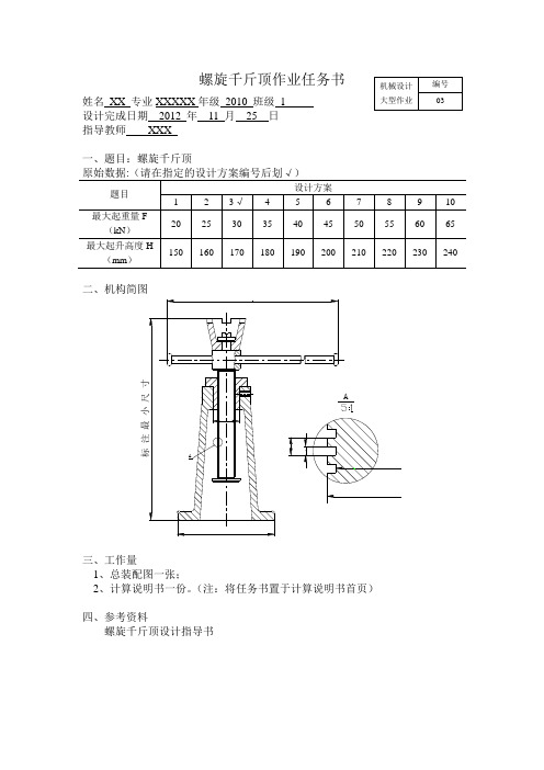
螺旋千斤顶作业任务书 姓名 XX 专业XXXXX 年级 2010 班级 1设计完成日期 2012 年 11 月 25 日 指导教师 XXX一、题目:螺旋千斤顶原始数据:(请在指定的设计方案编号后划√)题目 设计方案1 2 3√ 4 5 6 7 8 9 10 最大起重量F (kN ) 20 25 30 35 40 45 50 55 60 65 最大起升高度H(mm )150160170180190200210220230240二、机构简图标 注 最 小 尺 寸AA三、工作量1、总装配图一张;2、计算说明书一份。
(注:将任务书置于计算说明书首页)四、参考资料螺旋千斤顶设计指导书机械设计 大型作业编号03目录一、设计题目 (4)二、螺杆的设计与计算2.1 螺纹的牙型 (3)2.2螺杆的材料 (3)2.3螺纹直径 (3)2.4自锁验算 (4)2.5其他结构设计 (5)2.6螺杆的强度校核 (5)三、螺母的设计与计算3.1材料 (6)3.2螺纹圈数Z与高度H (6)3.3螺母其他尺寸 (6)3.4螺母与底座的配合 (7)四、螺杆稳定性验算 (7)五、托杯的设计与计算 (8)六、手柄设计与计算 (8)6.1材料 (9)6.2手柄长度 (9)6.3手柄直径 (9)6.4其他结构 (10)七、底座设计11八、千斤顶的效率12计 算 及 说 明 结 果 一、设计题目螺旋千斤顶主要零件:螺杆、螺母、托杯、手柄和底座。
扳动手柄可使螺杆在固定螺母中旋转,从而将托杯上的重物举起或放落。
设计的原始数据:最大起重F=30KN 、最大升起高度H=170mm 。
二、螺杆的设计与计算:2.1 螺纹的牙型选用矩形螺纹,采用内径对中,配合选H8/h8,由于螺纹的径向间隙很小,在强度计算时不予考虑。
2.2螺杆的材料查资料]1[可知,螺杆可选用45钢,弹性模量MPa E 196=2.3螺纹直径螺杆工作时,同时受压力与扭矩的作用,因此它的计算可近似按紧螺栓联接的计算公式估算出螺纹内径,即:F=30KN H=170mmH8/h8螺杆45钢 弹性模量MPa E 196=[]σπFd 3.1x 41≥(1)参考资料]2[得知,螺杆的屈服极限MPa s 345=σ,取安全因数3=S ,得许用应力[]MPa Ss115==σσ (2) 将数据带入式(1)得螺纹内径估算值为mm d 78.201011510303.14631=⨯⨯⨯⨯⨯≥π (3) 根据经验公式4P 1d =,得mm P 20.5=。
千斤顶1-千斤顶装配图-PPT

1
2
千斤顶 装配图
3
1.结构分析、确定表达方案; 2.布图(画基准线)
4
1.结构分析、确定表达方案; 2.布图(画基准线)
5
千斤顶
6
3.画底图:底座(基础件)——螺杆
7
大家应该也有点累了,稍作休息
大家有疑问的,可以询问和交
8
——顶盖——螺钉
9
——画旋转杆
10
4. 检查描深
11
5. 标注尺寸、注写序号、填写标题栏和明细栏
12
5. 标注尺寸、注写序号、填写标题栏和明细栏
13
千斤顶装配图
14
千斤顶装配图
15千Leabharlann 顶装配图16千斤顶装配图
17
千斤顶装配图
18
千斤顶装配图
19
千斤顶装配图
20
千斤顶装配图
21
千斤顶装配图
22
千斤顶装配图
23
千斤顶1-千斤顶装配图

04 千斤顶的应用场景
汽车维修领域的应用
更换轮胎
千斤顶是汽车维修中更换轮胎必不可 少的工具,可以轻松地将汽车抬起, 方便拆卸和安装轮胎。
检查底盘部件
在汽车维修中,有时需要检查底盘部 件,如悬挂系统、刹车系统等,千斤 顶能够将汽车稳定地支撑起来,方便 技师进行底盘部件的检查和更换。
建筑工程领域的应用
千斤顶装配图的绘制
选择合适的视图
选择主视图、俯视图、左视图等合适 的视图来表达千斤顶的组成和装配关 系。
绘制装配示意图
根据确定的表达方案,绘制出千斤顶 的装配示意图,标明各零件的名称、 代号、数量、材料等。
绘制零件图
根据装配示意图,绘制出各零件的零 件图,包括零件的形状、尺寸、公差、 材料等。
检查和修改
舞台表演
在舞台表演中,有时需要使用千斤顶来调整舞台高度,以适应不同表演的需要。
05 千斤顶的保养与维护
千斤的保养方法
定期检查油量
保持清洁
在使用过程中,要定期检查千斤顶的油量 ,确保油量充足,以减少内部摩擦和磨损 。
在使用过程中,要保持千斤顶的清洁,避 免灰尘和杂物进入内部,影响其正常工作 。
定期更换油
千斤顶1-千斤顶装配 图
目录
CONTENTS
• 千斤顶概述 • 千斤顶装配图详解 • 千斤顶工作原理 • 千斤顶的应用场景 • 千斤顶的保养与维护
01 千斤顶概述
千斤顶的定义
总结词
千斤顶是一种用于顶起重物的设备,通常由一个油缸和一个工作活塞组成。
详细描述
千斤顶是一种常用的重型设备,用于在无法使用其他工具或方法的情况下顶起 重物。它通常由一个油缸和一个工作活塞组成,通过油缸中的液压油传递压力, 使活塞上升或下降,从而将重物顶起。
内卡式千斤顶使用说明书

YDC N系列内卡式千斤顶使用说明书柳州欧维姆机械股份有限公司目录一、使用范围二、型号编码三、技术性能四、基本构造五、使用方法六、附件选用七、维护保养八、注意事项九、易损件明细表一、使用范围YDC N系列内卡式千斤顶是与OVM预应力锚固体系配套的张拉设备,是一种预应力穿心式千斤顶,它具有结构紧凑、密封性能好等特点。
同时,它将工具锚内置,有效地节省了千斤顶张拉所需的空间,特别适合狭小空间的张拉,也可大量节约预应力筋材料。
可广泛应用于先张和后张法的预应力混凝土结构、桥梁、电站、公路、高层建筑、岩土锚固等施工工程中。
配用不同孔数的内卡装置,可分别张拉19孔及以下孔数的OVM型夹片群锚。
二、型号编码YDC N系列内卡式千斤顶型号含义:Y D C ××××N ×××张拉行程(mm)内卡式公称张拉力(kN)穿心式千斤顶液压式三、技术性能YDC N系列内卡式千斤顶目前有1000kN、1500kN、2500kN、2800kN、3000kN、3500kN、4000kN等七个级别,行程有100mm、200mm两种规格。
其技术性能见表1型号项目YDC1000N-100 YDC1000N-200 YDC1500N-100 YDC1500N-200公称张拉力(kN) 997 997 1493 1493公称油压(MPa) 55 55 54 54张拉活塞面积(m2) ×10-2 ×10-2×10-2 ×10⁻²回程活塞面积(m2) ×10-3 ×10-3×10-2 ×10⁻²回程油压(MPa) 25 25 25 25张拉行程(mm) 100 200 100 200主机质量(kg) 78 98 116 146 外形尺寸长度L×直径Φ(mm)289×Ф250 389×Ф250 285×Ф305 385×Ф305最小工作空间A(mm)×C(mm)800×170 1000×170 800×200 1000×200 钢绞线预留长度(mm) 200 200 200 200配用锚具规格、3、4、5 、3、4、5、4、5、6、7、4、5、6、7型号项目YDC2500N-100 YDC2500N-200公称张拉力(kN) 2462 2462公称油压(MPa) 50 50张拉活塞面积(m2) ×10-2 ×10⁻²回程活塞面积(m2) ×10-2 ×10⁻²回程油压(MPa) 25 25张拉行程(mm) 100 200主机质量(kg) 217 263 外形尺寸长度L×直径Φ(mm)289×Ф399 389×Ф399最小工作空间A(mm)×C(mm)800×250 1000×250钢绞线预留长度(mm) 200 200配用锚具规格、7、8、9、10、11、12、、7、8、9、10、11、12、型号YDC2800N-100 YDC2800N-200 项目公称张拉力(kN) 2788 2788公称油压(MPa) 51 51张拉活塞面积(m2) ×10-2 ×10⁻²回程活塞面积(m2) ×10-2 ×10⁻²回程油压(MPa) 25 25张拉行程(mm) 100 200主机质量(kg) 237 288 外形尺寸289×Ф410 389×Ф410长度L×直径Φ(mm)800×260 1000×260最小工作空间A(mm)×C(mm)钢绞线预留长度(mm) 200 200配用锚具规格、7、8、9、10、11、12、、7、8、9、10、11、12、型号YDC3000N-100 YDC3000N-200 项目公称张拉力(kN) 3012 3012公称油压(MPa) 50 50张拉活塞面积(m2) ×10-2 ×10⁻²回程活塞面积(m2) ×10-2 ×10⁻²回程油压(MPa) 25 25张拉行程(mm) 100 200主机质量(kg) 350 350 外形尺寸289×Ф420 289×Ф420长度L×直径Φ(mm)最小工作空间900×270 1100×270A(mm)×C(mm)钢绞线预留长度(mm) 250 250配用锚具规格、13、14、15、16 、13、14、15、16型号YDC3500N-100 YDC3500N-200项目公称张拉力(kN) 3500 3500公称油压(MPa) 54 54张拉活塞面积(m2) ×10-2 ×10⁻²回程活塞面积(m2) ×10-2 ×10⁻²回程油压(MPa) 25 25张拉行程(mm) 100 200主机质量(kg) 350 350360×Ф470 460×Ф470 外形尺寸长度L×直径Φ(mm)900×290 1100×290最小工作空间A(mm)×C(mm)钢绞线预留长度(mm) 250 250配用锚具规格、13、14、15、16 、13、14、15、16型号YDC4000N-100 YDC4000N-200项目公称张拉力(kN) 4000 4000公称油压(MPa) 52 52张拉活塞面积(m2) ×10-2 ×10⁻²回程活塞面积(m2) ×10-2 ×10⁻²回程油压(MPa) 25 25张拉行程(mm) 100 200主机质量(kg) 400 480360×Ф490 460×Ф490 外形尺寸长度L×直径Φ(mm)最小工作空间900×300 1100×300A(mm)×C(mm)钢绞线预留长度(mm) 250 250配用锚具规格、13、14、15、16、17、18、19 、13、14、15、16、17、18、19 四、基本构造本内卡式千斤顶采用动缸式结构。
【说明书】千斤顶课程设计

【关键字】说明书千斤顶设计说明书院系班级学号设计人指导教师完成日期螺旋千斤顶设计过程千斤顶一般由底座1,螺杆4、螺母5、托杯10,手柄7等零件所组成(见图1―1)。
螺杆在固定螺母中旋转,并上下升降,把托杯上的重物举起或放落。
设计时某些零件的主要尺寸是通过理论计算确定的,其它结构尺寸则是根据经验公式或制造工艺决定的,必要时才进行强度验算。
设计的原始数据是:最大起重量F=20KN和最大提升高度H=.1.5结构(见图1―2)螺杆上端用于支承托杯10并在其中插装手柄7,因此需要加大直径。
手柄孔径d k的大小根据手柄直径d p决定,d k≥d p十0.5mm。
由后面的计算可知手柄的直径pd=25mm,所以mmdk8.268.026=+=。
为了便于切制螺纹,螺纹上端应设有退刀槽。
退刀槽的直径d4应比螺杆小径d1约小0.2~0.5mm。
mmdd6.204.014=-=。
退刀槽的宽度可取为1.5P=15mm。
为了便于螺杆旋入螺母,螺杆下端应有倒角或制成稍小于d1的圆柱体。
为了防止工作时螺杆从螺母中脱出,在螺杆下端必须安置钢制挡圈(GB/T891-1986)mmHmmD5,45==,挡圈用紧定螺钉(GB/T68-2000)166⨯M固定在螺杆端部。
1.5P=15mm计算项目计算及说明计算结果(1)螺母与底座的配合常用或等;(2)为防止螺母转动,应设紧定螺钉,直径常取M6~M12,根据起重大小决定;(3)为防止托杯脱落和螺杆旋出螺母,在螺杆上下两端安装安全挡圈;(4)连接螺钉,挡圈,挡环的规格尺寸按结构需要选取或设计;(5)为减少摩揩、磨损及托杯工作时不转动,螺旋副及托杯与螺杆的接触面均需润滑;(6)装配图尺寸标注应包括特性尺寸(如最大起落高度)、安装尺寸、外形尺寸(总厂、总宽、总高)和派和尺寸等;(7)图面应注明技术特性及技术要求;(8)图纸规格应符合之徒规定,绘图要按国家标准,标题栏和明细表的格式应符合要求,详见课程设计教材,或采用学生用标题栏及明细表格式;(9)设计计算说明书应在全部计算及图纸完成后进行整理编写。
YN4000千斤顶说明书

YDC4000N-100千斤顶使用说明书四平市欧维姆机械有限公司一、用途YDC4000N-100型千斤顶是一种内卡式张拉群锚的穿心式千斤顶,可配19孔及19孔以下的锚具进行张拉,广泛适用于先张、后张拉法的预应力混凝土结构、构件、桥梁、水工结构、核电站安全壳、岩石锚固、坝基锚固等工程。
二、型号及技术参数型号:YDC4000N-100公称张拉力:4000KN张拉面积:7.693X10⁻²m2额定油压:52MPa张拉行程:100mm三、构造及工作原理该千斤顶的缸体与缸盖采用螺纹连接,动密封采用格莱圈密封,固定密封采用两道O形密封圈,千斤顶内有前置锚具、限位板、导向杆、弹簧、挡板等,张拉不同孔数锚具时,更换相应孔数的内卡装置即可。
使用前,工具锚锚环锥孔全部涂石蜡。
在张拉过程中,重复使用一段时间后应对工具锚夹片进行检查,如发现有损伤,应及时更换夹片。
图1千斤顶结构示意图四、使用方法1、安装好工作锚具后,千斤顶回程到底升压至5MPa后,再穿入钢绞线,用磨好端头的钢绞线试插千斤顶里的夹片,使之完全归位。
安装好即可开始张拉。
2、按图1所示,将B路截止阀和节流阀打开,使B路处于回油状态,关闭A路使之处于进油状态,调整A路节流阀控制A路油速度和升压,张拉开始。
3、在活塞外伸时,工具锚夹具可自行夹紧钢绞线,工作锚中的夹片此时因受限位套的支托,退出不会太多。
4、当张拉完毕即可停止向A路供油,打开A路节流阀,同时转回截止阀,A路压力至零点,由于钢绞线束的回缩,活塞回程到若干毫米,工作锚的夹片被连动带入锚板内部自行夹紧。
5、B路关闭截止阀调整节流阀,控制流量和升压,活塞回程到底,起压小于20MPa停泵,此时完成一次张拉循环。
五、注意事项使用本千斤顶时,除应遵守一般预应力施工操作的有关规范外,还应注意以下问题。
1、千斤顶应采用优质矿物油,油内不含水及其它混合物,在通常温度下不分解、不变质,油液应严格保持清洁,经常过滤、定期更换,建议冬季用YC-N15号液压油,夏季用YB-N32号液压油。
简单千斤顶设计说明书
目录第一章设计题目及材料选择 (2)1.1设计题目 (2)1.2设计要求 (2)1.3主要零件的常用材料 (2)1.4千斤顶结构示意图 (2)第二章主要零件受力分析 (3)第三章螺杆的设计计算 (3)3.1螺杆牙型选择 (3)3.2按抗压,扭强度计算螺纹直径 (3)3.3精确校核螺旋强度 (4)3.4按耐磨性初步计算螺母高度 (4)3.5稳定性校核 (5)3.6自锁性校核 (5)第四章螺母的设计计算 (6)4.1根据螺旋的螺纹直径查的螺母大径 (6)4.2校核螺纹牙强度 (6)4.3螺母凸缘强度校核 (7)4.4螺母尺寸 (7)第五章托杯的设计与计算 (8)第六章手柄设计与计算 (8)6.1力矩分析 (8)6.2手柄直径dh (9)6.3手柄长度Lp (9)第七章底座设计 (9)第八章轴承选取 (10)第一章设计题目及材料选择1.1设计题目设计简单千斤顶的螺杆和螺母级其他结构的主要尺寸。
起重量为6.6t(约66000N),起重高度为180mm,间歇工作,可用于比较狭窄的工作场合。
1.2设计要求螺旋千斤顶是用人力转动手柄来举升重物的机械,它应有以下几个要求:a.能满足将5.5t重物举起180mm的功能,并能平稳的下降且具有足够的使用寿命。
b.在上升及下降过程中,可以停在任意位置而不自行下滑。
c.人手推力不可以过大,防止人产生过度疲劳。
d.千斤顶的支承面与重物之间不能有相对滑动,千斤顶与地面有足够的接触面积。
e.除以上要求外,还应保证工作可靠,操作安全,加工经济等。
1.3主要零件的常用材料螺杆:45螺母:ZQSn10-1底座:HT150托杯:Q235手柄:A31.4千斤顶结构示意图第二章 主要零件受力分析图1和图2分别表示螺杆和螺母的受力情况。
螺杆除受压力Q 外,还受转矩,即螺母的摩擦力矩T 1和推力轴承的摩擦力矩T 2。
其中T 2由以下公式求得F d T 22μ= (1) 其中:μ——滚动轴承的摩擦系数,对单向推力轴承μ=0.0013~0.0020d ——轴承内径,mmF ——轴承负荷,对推力轴承是轴向负荷,NT 1和压力Q第三章 螺杆的设计计算3.1螺杆牙型选择考虑到螺旋千斤顶要求在上升及下降过程中,可以停在任意位置而不自行下滑(即有自锁能力),又要使结构简单,故采用滑动螺旋,并选用梯形螺纹,牙型角α=30°,梯形螺纹内外螺纹以锥面相结合,不易松动,牙形可按照GB5796.1—86的规定。
- 1、下载文档前请自行甄别文档内容的完整性,平台不提供额外的编辑、内容补充、找答案等附加服务。
- 2、"仅部分预览"的文档,不可在线预览部分如存在完整性等问题,可反馈申请退款(可完整预览的文档不适用该条件!)。
- 3、如文档侵犯您的权益,请联系客服反馈,我们会尽快为您处理(人工客服工作时间:9:00-18:30)。
千 斤 顶 装 配 设 计 说 明 书
一 .设计目的
通过设计训练,掌握基本的先进设计制造过程及方法,掌握CAD、UG等软件进行三维实体造型、部件或机器装配、运动仿真、工程图绘制方法。
二.设计要求
1.用Pro /E、UG等软件绘制零件的三维实体造型;
2.把各个零件装配成一个装配体,并进行运动仿真,主要零件总和不得少于五个;
(3)根据要加工零件“国际象棋后”的AutoCAD工程图尺寸,进行手工编程如下。
%1234
t0101 m03s300 g90g00x31z1 g71u1.5r2p01q02x0.2z0.2f10000
n01g01x19z0 g03x21z-1r1 g01x21z-14 X18Z-45 g03x19.42z-46.7R1 g02x19.18z-47.5r0.7 X24.6Z-50.2R6 g03x27z-57R3.9 g01X27Z-62 N02x25z-63 g00x32z-63 g00X50z50
2.测量器具:直尺与游标卡尺
3.实践所用材料:直径为30mm的铝棒
五.实践步骤(包含加工程序)
1、内容
加工出图图1-1所示的工件。
图1-1
2、工艺规程编制
(1)工艺路线如下
下料→平右端面→倒圆角→车外圆→精车外圆→粗车锥面→精车锥面→车退刀槽→切断→铣十字槽→铣内圆柱面。
(2)工艺装备
用三爪卡盘夹持,用到外圆车刀、圆弧车刀、铣刀、切断刀,用游标卡尺或千分尺检测尺寸。
T0100
T0303
g00x22z-10
g71U1R1P03Q04X0.2Z0.2F150
Nr1
g01x17z-13
X17Z-16
g03x13z-18r2
N04g01x17.62z-43
g00X30z-43
g00X50Z50
t0300
m05 m30
3.操作步骤
2.实践组别.......................................
3.实践时间与地点.................................
二.实践目的.........................................
三.实践要求.........................................
3.选取装配体中的一个关键零件,绘制其工程图,按国家标准进行要求;
4.设计及加工工艺计算说明书要求:
(1)各个零件设计的步骤及尺寸计算,并要求有一定的过辅助图说明;
(2)装配体的总成图、爆炸图、各个零件的图应包含在说明书中(图要求截屏)。
三.设计内容
设计绘制一个千斤顶,并对它进行运动仿真。
四、千斤顶的组成及装配
3.学会简单零件的手工编程,并掌握机床的对刀操作。
4.了解数控加工的整个过程,能解决数控加工过程出现的问题。
三.实践要求
1.利用数控机床(包括数控车床和数控铣床)加工零件。
2.初步掌握华中模拟软件的应用,并对零件进行数控加工编程。
四.实践加工所用到的设备和测量器具以及材料
1.实践加工的设备:数控车床与数控铣床
4、画绞杠.................................
5、画螺纹杆...............................
6、画螺钉M8*12...........................
7、画顶垫.................................
3、操作步骤...........................................................................
4、走刀路线 如下图所示...........................
5、总结....................................................................................
二.设计要求......................................
三、设计的内容....................................
四.千斤顶的组成及装配............................
五、千斤顶的工作原理..............................
综合课程设计说明书
(2012-2013学年第一学期)
学 院:机械与电气工程学院
专 业:机械设计制造及自动化
姓 名:
学 号:
指导教师:
时 间:2012年12月14日-2013年1月11日
《一》机械CAD\CAM课程设计部分
千 斤 顶 装 配 设 计 说 明 书
一、设计的目的....................................
最后是进行零件的顺序运动:
先是接触个零件的约束,
再建立新的顺序,
然后对零件进行运动。
千斤顶的爆炸图如图:
《二》数控加工技术实践计划
国际象棋车加工
一、实践分配.....................................
1.实践内容....................................
六.千斤顶各零件图的绘制步骤。
千斤顶零件图如下:
1、底座
先打开UG,并建立草图:
开画底座的轮廓:约束
建立好中心线后开始作图:
最后得出所需的轮廓:
然后就可以完成草图,并且进行回转:
输入数据就可以得出所需零件:
然后所需的边进行倒角:
倒角完之后,就进行打孔:
然后进行定位:
然后输入相应的数据,就可以得出效果图:
千斤顶是由底座、螺套、绞杠、螺旋杆、顶垫和两枚规格不同的螺钉装配而成。装配的过程从底座开始,螺套嵌压底座中,一边用螺钉固定以防止螺套和底座之间的相对运动。螺旋杆的球面形顶部套上一个顶垫,用螺钉连接,以防止顶垫脱落或随螺旋杆一起旋转。
五、千斤顶的工作原理
千斤顶是简单起重工具,在工作时,用可调节力臂长度的绞杠带动螺旋杆在螺套中作旋转运动,螺旋作用螺栓杆上升,装在螺栓杆头部的顶垫顶起重物。骑缝安装的螺钉M10阻止螺套回转,顶垫与螺旋杆头部以球面接触,其内径与螺栓杆有较大间隙,即可减小摩擦力不使顶垫随同螺栓杆回转,又可自调心使顶垫上平面与重物贴平;螺钉M8可防止顶垫脱出。
四.实践加工所用到的设备和测量器具以及材料...........
五.实践步骤(包含加工程序)..........................
1、内容........................................................................
2、工艺规程编制........................................................
4.走刀路线 如下图所示:
图1-2走刀路线图
5.总结
通过本次两周的课程设计实习,我对数控机床有更加的深入了解和认识,巩固了所学过的数控编程,把以前在课本上所学到的知识及理论充分运用到实际操作中来,做到理论联系实践,让我感觉到实际操中和课本中的理论知识之间还是存在一定的差别的。
同样完成以下步骤:
然后继续建立凸台完成图形:
建基准平面
打孔并定位
画外螺纹
6、画螺钉M8*12
画圆柱并倒斜角、割键槽步骤M10螺钉是一样的
画螺钉M8外螺纹
7、画顶垫
创建草图,通过画直线并约束来画顶垫的外形
通过回转功能画顶垫的实体图
创建基准平面、打孔、定位、画螺纹
对以上的零件进行装配:
然后继续加载其他部件并约束:
六、千斤顶各零件图的绘制步骤......................
1、画底座....................................
2、画螺套画圆柱..................................
3、画螺钉M10*12..........................
国际象棋车加工
一、实践分配
1.实践内容:加工国际象棋“车”
2.实践组别:第二大组第六小组
3.实践时间与地点
3.1时间:2012-12-31至2013-1-11
3.2地点:贵州师范大学实训大楼
二.实践目的
1.掌握零件加工工艺编制,合理选择加工的工量器具、制定规范的工艺参数,对零件进行加工。
2.掌握华中模拟软件的应用,能进行程序的编辑与效验,初步掌握数控机床的加工操作,能加工实物。
(1).将数控机床开启进行回零操作
(2).将棒料夹持在机床三爪卡盘上
(3).用试切法进行对刀并将相应的刀具半径补偿值和刀具长度补偿值输入系统中
(4).将所编制好的程序输入系统进行调试加工
(5).加工过程中要关注刀具走向,不能擅自离开机床
(6).加工完后用游标卡尺或千分尺检测其尺寸符合后,关闭机床电源
对孔进行打螺纹:
最后得出完整的底座:
2、画螺套
画圆柱
画凸台及其定位
倒凸台斜角
打孔及其定位
画螺纹及其定位
打孔、定位、画螺纹
3、画螺钉M10*12
画圆柱并倒斜角
画槽
画外螺纹
4、画绞杠
画圆柱并倒斜角
5、画螺纹杆
画连续凸台并倒斜角
然后继续采用凸台命令,并且对中得出最后图形:
做几条投影线:
得到:
进一步完成草图并约束圆: