多屏互动协议华曦达(SDMC)DV6801-S2
西安诺瓦星云科技股份有限公司 4K UHD 1×4 视频分配器 用户手册说明书

4K UHD 1×4视频分配器文档版本: V1.0.0 文档编号:NS110000696用户手册西安诺瓦星云科技股份有限公司版权所有©2019 西安诺瓦电子科技有限公司。
保留一切权利。
非经本公司书面许可,任何单位和个人不得擅自摘抄、复制本文档内容的部分或全部,并不得以任何形式传播。
商标声明是诺瓦科技的注册商标。
声明欢迎您选用西安诺瓦电子科技有限公司(以下简称诺瓦科技)的产品,如果本文档为您了解和使用产品带来帮助和便利,我们深感欣慰。
我们在编写文档时力求精确可靠,随时可能对内容进行修改或变更,恕不另行通知。
如果您在使用中遇到任何问题,或者有好的建议,请按照文档提供的联系方式联系我们。
对您在使用中遇到的问题,我们会尽力给予支持,对您提出的建议,我们衷心感谢并会尽快评估采纳。
西安诺瓦星云科技股份有限公司用户手册更新记录更新记录西安诺瓦星云科技股份有限用户手册目录目录更新记录 .............................................................................................................................. i i1 简介 (4)2 特性 (5)3 外观 (6)4 尺寸 (8)5 应用场景 (9)6 菜单操作 (10)6.1 操作说明 (10)6.2 主界面 (10)6.3 主菜单 (10)7 产品规格 (13)8 常见问题处理 (14)西安诺瓦星云科技股份有限公司1 简介4K UHD 1×4是诺瓦科技开发的一款高性能、高稳定性、高清晰的4K视频分配器。
单台设备支持高达4096×2160@60Hz分辨率输入和输出,支持1路HDMI2.0输入,4路HDMI2.0实时输出,输入与输出分辨率一致。
操作方便,即插即用,适用于HDMI接口设备,兼容多种机顶盒、DVD、播放盒等。
蕊美达65英寸互动教育显示板产品介绍说明书

Philips Signage Solutions E-Line Display65"Powered by Android Multi-touch65BDL3052EInteractive education displayFeaturing multi-touch technologyThe Philips E-Line touch display maximises engagement and inspires collaboration with up to 20 touchpoints. Powered by Android and featuring a toughened anti-glare glass, it's made to withstand heavy daily usage in the classroom.Interactive and collaborative•Operate, monitor and maintain with CMND and Control •Multi-touch technology capable of 20 touchpoints •Advanced IR touch with smaller, shallower bezelsSmart and powerful•OPS slot allows for PC embedding without cabling •Whiteboard mode built in•Android: Run your own app or choose your favourite app to run •0-gap touch frame•Anti-glare toughened glass 7 MOHSHighlightsPowered by AndroidWith Android OS integrated into the display, you can work with the most developed OS on the planet and save your own app directly into the display. Or, choose from the large library of Android apps and play content from there. With the built-in scheduler, you can daypart your apps and content based on yourcustomer and time of day and with the auto-orientation feature, showing content inportrait or landscape is as simple as turning the display.CMND and ControlRun your display network over a local (LAN) connection. CMND and Control allows you toperform vital functions like controlling inputs and monitoring display status. Whether you're in charge of one screen or 100.Multi-touch technologyCreate a memorable interactive experience with up to 20 touchpoints at the same time. Perfect for collaborative and competitive applications, this display connects youraudience with any content - making it ideal for education, public venues, corporate,hospitality and retail settings. The touch panel is HID compliant, providing true plug-and-play operation.OPS slotIntegrate a full-power PC or Android-powered CRD50 module directly into your Philips Professional Display. The OPS slot contains all the connections you need to run your slot-in solution, including a power supply.Whiteboard mode built inInspire agile collaboration with whiteboard mode. Simply activate this feature to turn your display into a blank canvas that can be drawn on by multiple users by hand or with dedicated display markers. Everything on the screen can then be captured for easy printing or filesharing.Issue date 2022-10-19 Version: 4.0.112 NC: 8670 001 81396 EAN: 87 12581 78528 4© 2022 Koninklijke Philips N.V.All Rights reserved.Specifications are subject to change without notice. Trademarks are the property of Koninklijke Philips N.V. or their respective owners.SpecificationsPicture/Display•Diagonal screen size: 65 inch / 163.9 cm •Panel resolution: 3840 x 2160•Optimum resolution: 3840 x 2160 @ 60 Hz •Brightness: 350 cd/m²•Response time (typical): 8 ms•Aspect ratio: 16:9•Viewing Angle (H / V): 178 / 178 degree•Pixel pitch: 0.372 (H) x 0.372 (V) [mm]•Display colours: 1.07 B•Picture enhancement: 3/2 - 2/2 motion pull down, 3D Combfilter, Motion compens. deinterlacing, Progressive scan, 3D MA deinterlacing, Dynamic contrast enhancement•Panel technology: ADS•Contrast ratio (typical): 1200:1•Operating system: Android 8.0•OS UI resolution: 1920 x 1080 @ 60 Hz Supported Display Resolution •Computer formatsResolution Refresh rate720 x 400 70 Hz832 x 624 75 Hz1440 x 900 60 Hz1600 x 900 60 Hz1680 x 1050 60 Hz1920 x 1080 60 Hz1024 x 768 60 Hz1152 x 870 75 Hz1280 x 1024 60 Hz1280 x 720 60 Hz3840 x 2160 30, 60 Hz640 x 480 60, 67, 75 Hz800 x 600 60 Hz•Video formatsResolution Refresh rate480i 60 Hz480p 60 Hz720p 50, 60 Hz1080i 50, 60 Hz1080p 50, 60 Hz2160p 30, 60 Hz576i 50 Hz576p 50 HzConnectivity•Video input: DVI-D (x 1), HDMI 2.0 (x 3), VGA (Analogue D-Sub) (x 1), USB 2.0 (x4), USB-C (up to 65 W)•Audio input: 3.5 mm mini jack (x 1)•Audio output: 3.5 mm Mini Jack (x 1)•External control: IR (in/out) 3.5 mm jack, RJ45, RS232C (in/out) 2.5 mm jack•Other connections: OPS, micro SD, USB-B (x 3) Convenience•Placement: Landscape (18/7)•Screen-saving functions: Pixel Shift, Low Brightness •Signal loop through: RS232, IR Loop through •Ease of installation: AC Out, Smart Insert •Network controllable: RS232, RJ45•Keyboard control: Lockable •Remote control signal: Lockable•Other convenience: Carrying handlesOperating conditions•Temperature range (operation): 0 ~ 40 °C•Temperature range (storage): -20~60 °C•Altitude: 0 ~ 3000 m•MTBF: 50,000 hour(s)•Humidity range (operation)[RH]: 20–80% (withoutcondensation)•Humidity range (storage) [RH]: 5–95% (withoutcondensation)Power•Consumption (Typical): 155 W•Consumption (Max): 376 W•Standby power consumption: <0.5 W•Mains power: 100 ~ 240 VAC, 50/60 Hz•Power Saving Features: Smart Power•Energy Label Class: GSound•Built-in speakers: 2 x 15 WAccessories•Optional accessories: Interact dongles•Included Accessories: Cleaning cloth (x 1), HDMICable (3 m) (x 1), IR sensor cable (1.8 m) (x 1),Philips logo (x 1), Quick start guide (x 1), Remotecontrol and AAA batteries, RS232 daisy chain cable(x 1), Touch Pen (x 2), USB A to B cable (3 m)(x 1), RS232 cable, AC Power Cord, Cable clip(x 3), AC switch cover and Screw x 1, DVI-Dcable, USB cover and screwsMiscellaneous•On-Screen Display Languages: Arabic, Dutch,Danish, English, French, Finnish, German, Italian,Japanese, Norwegian, Polish, Portuguese, Russian,Spanish, Swedish, Simplified Chinese, Turkish,Traditional Chinese•Regulatory approvals: CE, FCC, Class A, RoHS,CB, EAC, EMF, ETL•Warranty: 5-year warrantyMultimedia Applications•USB Playback Video: H.263, H.264, H.265, MPEG1/2, MPEG4, VP9•USB Playback Picture: BMP, JPEG, PNG•USB Playback Audio: AAC, MPEG, HEAACInteractivity•Multi-touch technology: 0-gap Infrared touch•Touch points: 20 simultaneous touch points•Plug and play: HID compliant•Protection glass: Anti-Glare, Tempered safety glass7 MOHSWeight•Product with packaging (kg): 52.7 kg•Product with packaging (lb): 116.18 lb•Product without stand (kg): 43.15 kg•Product without stand (lb): 95.13 lbInternal Player•CPU:2 x A53 + 2 x A73•GPU: ARM Mali G51•Memory:3 GB DDR3•Storage: 16 GB EMMCDimensions•Smart Insert mount: 100 x 100 mm, 6xM4L6•Set dimensions(W x H x D):1494.3 x 883.2 x 99.5 mm(D_Max)/78.5 mm(D_Wallmount) mm•Set dimensions in inch (W x H x D):58.83 x 34.77 x 3.92 (D_Max)/3.09(D_Wallmount) inch•Bezel width:17.8 mm(T/R/L) x 31.7 mm(B)•Wall Mount: 400 x 400 mm, M8•Weight:43.15 kg。
杭州希康维数字科技有限公司产品使用及管理指南说明书
Barrier GateUser ManualLegal Information©2022 Hangzhou Hikvision Digital Technology Co., Ltd. All rights reserved.About this ManualThe Manual includes instructions for using and managing the Product. Pictures, charts, images and all other information hereinafter are for description and explanation only. The information contained in the Manual is subject to change, without notice, due to firmware updates or other reasons. Please find the latest version of this Manual at the Hikvision website ( https:/// ).Please use this Manual with the guidance and assistance of professionals trained in supporting the Product.Trademarksand other Hikvision's trademarks and logos are the properties of Hikvision in various jurisdictions.Other trademarks and logos mentioned are the properties of their respective owners. DisclaimerTO THE MAXIMUM EXTENT PERMITTED BY APPLICABLE LAW, THIS MANUAL AND THE PRODUCT DESCRIBED, WITH ITS HARDWARE, SOFTWARE AND FIRMWARE, ARE PROVIDED "AS IS" AND "WITH ALL FAULTS AND ERRORS". HIKVISION MAKES NO WARRANTIES, EXPRESS OR IMPLIED, INCLUDING WITHOUT LIMITATION, MERCHANTABILITY, SATISFACTORY QUALITY, OR FITNESS FOR A PARTICULAR PURPOSE. THE USE OF THE PRODUCT BY YOU IS AT YOUR OWN RISK. IN NO EVENT WILL HIKVISION BE LIABLE TO YOU FOR ANY SPECIAL, CONSEQUENTIAL, INCIDENTAL, OR INDIRECT DAMAGES, INCLUDING, AMONG OTHERS, DAMAGES FOR LOSS OF BUSINESS PROFITS, BUSINESS INTERRUPTION, OR LOSS OF DATA, CORRUPTION OF SYSTEMS, OR LOSS OF DOCUMENTATION, WHETHER BASED ON BREACH OF CONTRACT, TORT (INCLUDING NEGLIGENCE), PRODUCT LIABILITY, OR OTHERWISE, IN CONNECTION WITH THE USE OF THE PRODUCT, EVEN IF HIKVISION HAS BEEN ADVISED OF THE POSSIBILITY OF SUCH DAMAGES OR LOSS.YOU ACKNOWLEDGE THAT THE NATURE OF THE INTERNET PROVIDES FOR INHERENT SECURITY RISKS, AND HIKVISION SHALL NOT TAKE ANY RESPONSIBILITIES FOR ABNORMAL OPERATION, PRIVACY LEAKAGE OR OTHER DAMAGES RESULTING FROM CYBER-ATTACK, HACKER ATTACK, VIRUS INFECTION, OR OTHER INTERNET SECURITY RISKS; HOWEVER, HIKVISION WILL PROVIDE TIMELY TECHNICAL SUPPORT IF REQUIRED.YOU AGREE TO USE THIS PRODUCT IN COMPLIANCE WITH ALL APPLICABLE LAWS, AND YOU ARE SOLELY RESPONSIBLE FOR ENSURING THAT YOUR USE CONFORMS TO THE APPLICABLE LAW. ESPECIALLY, YOU ARE RESPONSIBLE, FOR USING THIS PRODUCT IN A MANNER THAT DOES NOT INFRINGE ON THE RIGHTS OF THIRD PARTIES, INCLUDING WITHOUT LIMITATION, RIGHTS OF PUBLICITY, INTELLECTUAL PROPERTY RIGHTS, OR DATA PROTECTION AND OTHER PRIVACY RIGHTS. YOU SHALL NOT USE THIS PRODUCT FOR ANY PROHIBITED END-USES, INCLUDING THEDEVELOPMENT OR PRODUCTION OF WEAPONS OF MASS DESTRUCTION, THE DEVELOPMENT OR PRODUCTION OF CHEMICAL OR BIOLOGICAL WEAPONS, ANY ACTIVITIES IN THE CONTEXT RELATED TO ANY NUCLEAR EXPLOSIVE OR UNSAFE NUCLEAR FUEL-CYCLE, OR IN SUPPORT OF HUMAN RIGHTS ABUSES.IN THE EVENT OF ANY CONFLICTS BETWEEN THIS MANUAL AND THE APPLICABLE LAW, THE LATTER PREVAILS.Symbol Conventions The symbols that may be found in this document are defined as follows.ContentsChapter 1 Introduction (1)1.1 Product Introduction (1)1.2 Key Feature (1)Chapter 2 Installation (2)2.1 Installation Environment (2)2.2 Install Barrier Gate (2)2.2.1 Fix Barrier Gate Host (2)2.2.2 Install Boom Pole (4)2.3 Wiring (5)2.3.1 Connect to Peripheral Devices (5)2.3.2 Connect to Power Supply (7)Chapter 3 Debug (9)3.1 Remote Control (9)3.2 Button Operation (9)Chapter 4 Maintenance (13)4.1 Check Regularly (13)4.2 Check After Collision (13)4.3 Fault Code Description (13)4.4 Troubleshooting for Failed Auto Rising/Falling of Boom Pole After Power Cutoff (15)Appendix A. Peripheral Device Interfaces Introduction (16)Chapter 1 Introduction1.1 Product IntroductionBarrier gate is the entrance and exit management device to limit motor vehicle passing. It can control the boom pole automatically via parking lot management system. Or you can control the boom pole via buttons on remote controller.Barrier gate is widely applicable to toll station, parking lot, the entrance and exit of community and unit, etc. Its working temperature ranges from -30 °C to 70 °C (-22 °F to 158 °F).1.2 Key Feature●Adopts direct current brushless motor which can run steadily, applicable to entrance and exit, ETC system, etc.●The boom pole can rise rapidly and fall slowly. The barrier gate can learn the rising and falling limit positions automatically after it is powered on.●Over-voltage and over-current protection to prevent the motor from being burnt caused by locked rotor during running.●Supports anti-fall function via inductive loop, IR, etc., and protection functions including pressure wave, resistance rebound, etc.●Adjustable boom pole direction from left to right or from right to left.Chapter 2 Installation2.1 Installation EnvironmentThe installation environment of the barrier gate should meet the following requirements.●The installation space should be large enough to guarantee the boom pole can rise or fall normally.●Install the barrier gate on horizontal ground.●Installation surface requirements:○If no base is installed, the installation surface must be firm enough to fix the host to guarantee the barrier gate can run stably.○If base is needed, it is recommended to install the base with quick setting cement. The base should be horizontal. The height should be larger than 300 mm. The length and width of base should be larger than those of the actual barrier gate installation surface. Bury the set bolts prepared by yourself before installation.●If the barrier gate is anti-collision, the boom pole will flick 90° in reverse direction if it is impacted. Make sure there is no obstacle in the range.●Bury the cables before installation. The conduit should be 50 mm higher than the ground to avoid the gathered water on the ground to enter into the cable and cause short circuit.2.2 Install Barrier Gate2.2.1 Fix Barrier Gate HostFollow the steps below to fix the host of barrier gate.Steps1.Mark the positions of holes on the refuge island as shown below. The hole depth is approx. 120 mm.Figure 2-1 Mark Positions of HolesThe suggestions for positions of holes:●The holes in vertical direction should be near to the boom pole.●If the entrance/exit is unidirectional, the holes should be in the horizontal center of the refugeisland. If the entrance/exit is bi-directional, the holes in the horizontal direction should be far away from the entrance/exit.2.Punch the four M12 × 150 expansion screws in the package into the marked positions on refuge island, and fasten the nuts to make the screws expand to grip the ground. Then unfasten thenuts.Figure 2-2 Install Expansion Screws3.Uninstall the top and front covers.1)Use the L-type key to unlock the top cover.2)Lift the top cover gently and push it to take it down.3)Lift the front cover gently to take it down.Figure 2-3 Uninstall Top and Front Covers4.Fix the host.1)Put the layers on the host bottom and parallel them to the rising or falling direction of theboom pole.2)Put the host on the positions of expansion screws on the refuge island to make the screwspass through the layers. Keep the layers parallel to the rising or falling direction of the boom pole.3)Fasten the expansion nuts on the screws to fix the host.Figure 2-4 Fix HostKeep the supporting bracket of the boom pole vertically upward to avoid accident.2.2.2 Install Boom PoleFollow the steps to install boom pole.Steps1.Align the holes on the supporting bracket with those on the boom pole.2.Insert four M8 screws into the holes.3.Install flat washers, spring washers, and nuts on both sides of the screws.4.Fasten the nuts to fix the boom pole.Figure 2-5 Install Boom PoleCautionContact the professional technical personnel to change the boom pole. You may damage the barrier gate if you change it by yourself.2.3 Wiring2.3.1 Connect to Peripheral DevicesThe barrier gate can connect to peripheral devices such as entrance/exit capture unit.Steps1.Open the top cover of the host, and you can see the interfaces to connect peripheral devices.2.Connect peripheral devices to the interfaces as shown below.Refer to "Peripheral Device Interfaces Introduction" for the detailed definition of the peripheraldevices interfaces.Figure 2-7 Connect to Peripheral Devices2.3.2 Connect to Power SupplyConnect the laid power cord (RVV3 × 1.5 mm2 or above) to the power input of barrier gate. Installthe top and front covers. Use the L-type key to lock the top cover.●Cut off the power before wiring.●The power voltage of barrier gate is 220 VAC ± 10%. If the voltage exceeds the range, voltage stabilizer is needed.●Make sure the barrier gate is connected to the ground firmly, or it may cause electric shock.Figure 2-8 Power InputChapter 3 DebugAfter the installation completes, power on the barrier gate, and it will operate self-check of rising to limit position.After the self-check completes, you can control the barrier gate via remote controller or buttons.3.1 Remote ControlAfter the self-check completes, you can control the boom pole to rise, fall, and stop via the remote controller leaving factory with the barrier gate.3.2 Button OperationOpen the top cover of the host, and you can see the buttons and nixie tube. You can control the barrier gate via the buttons and judge the status via the nixie tube.There is respective initial status for the rising limit position, falling limit position, and rising speed of the barrier gate. You can adjust them via buttons if the initial status cannot meet the requirements of the installation site.Figure 3-1 Control ButtonsNote●If you need to hold the buttons to trigger operations, hold for 3 seconds or above.●The nixie tube shows the status (e.g., H0) and fault codes (hexadecimal characters, e.g., 1A). If the fault codes appear on the nixie tube, it means there is operation error. Contact the technical personnel of our company to solve the problems.Table 3-1 Button Operation DescriptionThe controller can learn no more than 481.Press2.Holdadjust the boom pole to H5 status.Displayed fallingunit of thedurationPressnixie tube displays rL.Apply control signal to let the boom pole rise to the limit position.Holdadjust the boom pole to H8 status.HoldPressChapter 4 Maintenance4.1 Check RegularlyThe barrier gate should be maintained every three months. Check according to the following instructions.●Check mechanical drive.●Check if the wiring and GND is firm.●Check if the motor sounds abnormally.4.2 Check After Collision●Check if the slewer is damaged. Change it if it is damaged.●Check if the boom pole is curved. Change it if it is curved.●Check if the barrier gate sounds abnormally during running. Contact the qualified after-sales service agent in time.4.3 Fault Code DescriptionWhen the barrier gate is abnormal, open the top cover, and observe the fault code on the nixie tube to troubleshoot.Table 4-1 Fault Code Description4.4 Troubleshooting for Failed Auto Rising/Falling of Boom Pole After Power CutoffIf the boom pole cannot rise or fall automatically after the power is cut off suddenly, follow the steps to solve the problem.Steps1.Uninstall the top and front covers.2.Insert L-type wrench into the hexagonal hole on the host.Figure 4-1 Rotate Wrench3.Rotate the wrench according to the barrier gate status.-If the barrier gate is in the falling limit status, rotate the wrench anticlockwise to raise the boom pole slowly until it can rise and fall automatically.-If the barrier gate is in the rising limit status, rotate the wrench clockwise to make the boom pole fall slowly until it can rise and fall automatically.Appendix A. Peripheral Device InterfacesIntroductionOpen the top cover of host, and you can see the interfaces as shown below.Figure A-1 Interfaces Table A-1 Interface Description。
大连科迪数字转换分配器

大连科迪数字转换分配器到货时间约:5工作日功能及组成:该设备由一个机箱及4个接口模块组成,用于将广州亚运会组委会提供的公共信号数字SDI信号解嵌为音频信号和视频信号,并将两种数字信号转换模拟信号,同时可提供模拟音频信号和模拟视频信号8路的输出。
该设备包含如下5个配件:技术参数如下:1、DMA-6801嵌入式SDI到模拟音视频转换模块DMA-6801 是一款广播级的D/A编码模块和嵌入音频解嵌模块。
提供2路带嵌入音频的SDI输出、2路复合模拟视频输出和2路平衡模拟音频输出。
DMA-6801 可选择解嵌四个音频组中的任意一个音频组,并将其转换成模拟音频输出。
具有自动识别功能的嵌入音频的SDI 输入★具有自动识别功能的嵌入音频的SDI 输入★ 2路带嵌入音频的SDI 分配输出★ 2路10bit 广播级模拟复合视频输出★ 2路平衡模拟音频输出(4路可选)2、VDA-6801模拟视频分配放大模块、1分8VDA-6801视频分配放大模块是一种高质量,低成本的通用视频放大模块,可用于模拟复合、分量和副载波信号的分配放大。
视频增益从+3dB到-3dB可调,每个板卡提供8路模拟视频输出。
模块化插卡式分配器●模块化插卡式分配器●支持带电热插拔●非平衡输入,均衡输入可选●±3dB 增益调整范围●300米电缆(Belden8281)均衡补偿可选●模拟复合、分量和副载波分配的理想选择3、ADA-6801模拟音频1分8分配放大模块ADA-6801音频分配放大模块提供了广播系统、电视系统、传输系统和录音机房所需的音频分配功能。
它采用无变压器模块平衡输入,具有平衡非平衡转换电路,可以在非平衡信号输入时进行平衡非平衡转换,具有良好的输出隔离度,增益从-6dB至+20dB可以进行连续调节,具有良好的频率响应和极低的失真度。
● 低成本、高质量音频分配放大● 8路输出● +20dBu最大输出电平● -6dB~+20dB增益调整范围4、VSD-6801 SDI信号分配1分8、带均衡VSD-6801 数字分配放大模块提供一种SDI系统信号分配的低价格解决方案。
Dell EMC XC730xd 系列超融合设备解决方案指南说明书
Dell EMC XC730xd 系列超融合设备解决方案指南注意、小心和警告: “注意”表示帮助您更好地使用该产品的重要信息。
: “小心”表示可能会损坏硬件或导致数据丢失,并告诉您如何避免此类问题。
: “警告”表示可能会导致财产损失、人身伤害甚至死亡。
© 2018 - 2019 Dell Inc. 或其子公司。
保留所有权利Dell、EMC 和其他商标均是 Dell Inc. 或其子公司的商标。
其他商标可能是其各自所有者的商标。
2019 - 02Rev. A061 关于 Dell 超融合设备解决方案 (4)2 支持的硬件、固件和软件 (5)3 说明文件参考 (6)4 许可概览 (7)简易版许可证 (7)专业版和旗舰版许可证 (7)设置 Nutanix 客户门户 (7)许可证管理 (7)5 部署设备 (8)有关 SATADOM 的重要信息 (8)写密集型应用程序示例 (8)开始之前 (8)为首次使用设置您的 Dell XC730xd (9)“缺失 SD 卡”的引导错误消息 (9)部署概述 (10)默认群集凭据 (11)6 下载和安装软件应用程序 (12)在单独的服务器上安装 Dell OpenManage Essentials (12)Dell Nautilus (12)7 监测 (14)监测软件 (14)8 更新固件 (15)使用 Nutanix Life Cycle Manager (LCM) 更新 XC 硬件组件固件 (15)9 装回硬件 (16)装回不含群集数据的组件 (16)更换出故障的包含群集数据的前置 HDD 和 SSD 组件 (16)10 恢复系统 (17)11 获得帮助 (18)联系 Dell EMC (18)Dell SupportAssist (18)Locating service tag (18)Quick Resource Locator (19)目录3关于 Dell 超融合设备解决方案Dell 提供的超融合设备解决方案包括 Dell XC730xd 服务器和来自 Nutanix 的软件(用作虚拟设备),通过将计算机、存储和网络融合到群集环境下部署的一个设备中,从而简化虚拟化。
嵌入式多屏控制器DSCON3000产品手册

规格
标准 19 英寸 4U 高,10 插槽
网络接口 串行接口 USB 接口 接口 制式 接口 信号格式 接口 信号格式 接口
信号格式
接口
信号格式
接口
信号格式
信号格式
2 个 RJ45 接口,支持 10M/100M/1000M 网络 3 路 RS232 接口,用于连接矩阵、液晶显示屏、中控等设备 2 个 USB2.0 接口,1 个 USB3.0 接口 BNC (1.0VP-P,阻抗:75Ω) PAL/NTSC 自适应 BNC HD-SDI,符合 SMPTE-292M 标准,接口速率 1.485Gb/s BNC HDCVI,1280H,1920H DB15 接口 支持 VESA 2.0 标准,信号输入分辨率支持 1024×768@60Hz、 1280×1024@60Hz、1400×1050@60Hz、1600×1200@60Hz, 2048×1536@30Hz 以及自定义分辨率信号采集 DVI-I 数字视频接口输入,通过转换头支持 HDMI 信号 支持 DVI 1.0 以及 HDMI 1.3 规范 支持 12 位 HDMI 信号,支 持 xvYCC 色彩标准信号,输入分辨率支持 1024×768@60Hz、 1280×1024@60Hz、1400×1050@60Hz、1600×1200@60Hz, 720p、1080p 以及自定义分辨率信号采集 HDMI 支持 DVI 1.0 以及 HDMI 1.3 规范,支持 12 位 HDMI 信号, 支持 xvYCC 色彩标准信号,输入分辨率支持 1024× 768@60Hz、1280×1024@60Hz、1400×1050@60Hz、1600× 1200@60Hz、720p、1080p 以及自定义分辨率信号采集 输出分辨率最高支持 1920×1080@60Hz
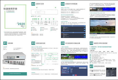
多方音视频互动系统 快速使用手册说明书
右上角 图标设置设备名称,以更好的标识设备。
授权码是主机与终端间互相发现的一个校验码,你可以点击右上角 启或主机与终端重新连接的时候进行校验。
1硬盘槽(定制) 指示灯2模拟音频输入和输出接口,另一端连接到网络交换机,连接到SDI 输入和输出双向音视频互动基础设置05按照以上3、4步骤分别安装好两台设备,将设备连接至交换机,并配置相同网段的IP 保证设备能够正常通讯。
电脑也接入同一交换机,配置同网段的IP 地址,登录设备的管理页面,首先在“媒体”--“视频源”查看已连接的本地视频源(左上角显示为LOCAL)输入图像是否正常,有视频正常输入的接口会显示视频画面,5s 更新一次;无视频输入的接口显示为蓝屏,请检查视频源和连接线是否正常。
1.查看本地视频源点击“发现”查看是否能够自动发现其他翼多设备,如果能够发现设备,将显示在左侧列表,设备图标显示为绿色(设备掉线后就无法显示)。
点击设备,选中其“所有视频源”,将其添加到本机作为视频源。
2.自动发现设备和添加视频源3.解码对端视频源并输出至显示设备在“媒体”界面,将已添加的REMOTE 设备的视频源拖动至输出窗口作为解码输出RTSP/RTMP 流输出,媒体源包括视频源列表的所有源和2个输出“添加发布点”-“发布点名称”,添加一个发布点。
“源选择”:点击“源选择”,根据需要,可选择需要输出的视频源,每个源均可以选择“流服务”:点击“流服务-添加流服务”,选择需要添加的服务类型并设置相应参数,支持RTSP 和RTMP 。
RTMP 配置方式如下:“状态”:配置完成“源选择”和“流服务”之后,可点击“状态”查看发布点的相关统计信息。
磁盘盒上有磁盘指示灯:磁盘挂载成功后会显示为绿灯常亮;初始化时磁盘绿灯不亮,初始化成功后绿灯常亮;正在录像时为绿灯闪烁;点击“录像设置”可以设置录像相关参数:文件限制可选根据大小或时长进行切割,也可不切割;录满之后自动切换到磁盘2,当2个磁盘都录满之后则停止录像。
UNIS高清解决方案

UNIS高清视频会议系统项目方案建议书清华紫光有限公司2009年 8月✓第一章视频会议概况1.1视频会议系统概述随着全球步入信息化时代,人们对了解事物、交换信息的要求已经从纸、笔、书本、话音等发展到通过声光电信号等各种方式更准确、更快捷、更丰富地表达出来。
在需求的推动下,多媒体计算机技术与通信技术相结合,逐渐发展成为一种新的边缘技术——多媒体通信技术。
个人计算机的普及、微电子技术和多媒体技术的飞速发展、综合业务数字网的建立及宽带综合业务数字网的研究进展,都有力地推动了多媒体通信的发展。
如果说19世纪是电报的时代,20世纪是电话的时代,那么,21世纪将是多媒体通信的时代。
随着数字信号处理、压缩编码技术和数据传输新技术的不断涌现,新产品层出不穷,同时出现了许多新的多媒体通信方式。
视听多媒体通信业务主要包括以下几种类型: ·多媒体会话型业务,如视频会议、可视电话、远程教育、远程医疗等;·多媒体检索型业务,如多媒体数据库查询;·多媒体分配型业务,如音频视频广播等;·多媒体电子信函型业务。
其中,作为多媒体会话型通信业务的一种典型,视频会议业务已在社会性的信息交流中发挥了巨大的沟通作用。
视频会议通过通信网络把两个或多个地点的多媒体会议终端连接起来,在其间传送各种图像、话音和数据信号,使出席会议者有亲临现场的感觉。
除了用于多点多媒体会议之外,视频会议系统还应用于远程教育、远程医疗等需要传送实时音频、视频和数据的业务。
视频会议能为用户提供直接、全面的沟通交流,并能节约时间、降低成本、提高生产率,因此巨大的市场需求推动了视频会议技术的发展。
国内、外很多科研机构和厂商都进行了多媒体多点会议通信系统的研究,并推出了各自的视频会议系统。
在研究各视频会议系统的基础上,国际电信联盟(ITU-T)形成了视听多媒体通信系统国际标准的H.200系列建议,使不同厂商的多媒体通信产品能够互通,推动了多媒体通信技术标准化的进程。