ES1(温度传感器使用说明书)
温度传感器的说明书

温度传感器的说明书尊敬的用户:感谢您购买我们的温度传感器产品。
为了确保您正确、安全地使用此产品,我们特别提供如下说明书,请仔细阅读并按照要求进行操作。
1. 产品概述温度传感器是一种用于测量温度的设备,可以将温度转化为电信号输出。
本产品采用高精度的数字温度传感器,并具备以下特点:- 超高精度:测量温度范围为-40℃至+125℃,精度可达±0.1℃。
- 快速响应:传感器具备快速响应时间,能够准确捕捉温度变化。
- 稳定可靠:采用优质材料和先进工艺制造,确保产品稳定可靠,长时间使用不易出现故障。
2. 使用方法本温度传感器为数字输出型产品,可通过以下步骤进行使用:步骤一:将传感器连接到计量仪器或控制系统的温度接口,确保接触良好。
步骤二:开启计量仪器或控制系统,并按照相关说明进行设置。
步骤三:进行温度测量,待测量结果稳定后,记录或进行进一步处理。
3. 注意事项为了保障您的安全和正常使用,请注意以下事项:- 请按照产品规定的工作温度范围使用,不要超出额定范围,以免影响测量准确性和传感器寿命。
- 请避免与水、油等液体直接接触,以免影响传感器性能和使用寿命。
- 请勿在高温、高湿度、强酸碱等恶劣环境中使用,以免损坏传感器。
- 避免传感器受到强磁场或电磁辐射的干扰,可能会导致测量偏差。
4. 维护保养- 定期清洁传感器外壳,可使用干净的软布轻擦,不要使用有机溶剂或大量水直接清洗。
- 如发现传感器接触异常或测量不准确,请及时联系售后服务,不要私自拆卸或修理。
5. 售后服务如有任何关于产品的使用问题或售后需求,请随时联系我们的客户服务团队,我们将竭诚为您提供技术支持和解决方案。
感谢您对我们产品的信任和支持,我们将一如既往地致力于为您提供高品质的产品和专业的服务。
祝您使用愉快!此致,敬礼。
厂商名称日期。
温度传感器说明书

DimensionalDrawings 4
Electricalconnection|HeadBig
Headunitwith1transmitter n( odisplay)andM12plug
Headunitwith1transmitter n( odisplay)andcablegland
V01
B
52.7 / 2.09
V52
F
66.0 / 2.60
V04
N
84.0 / 3.31
D2 [mm/inch] 31.0 / 1.22 50.0 / 1.97 68.0 / 2.68
FOOD
Processconnectionswithextendedtemperaturerange
CH|1 CLEANadaptM21
6mm
t50¡1.8s t90¡5.2s D: 8, 10, 12 mm
D
4mm
t50¡1.2s t90¡3.5s D: 6, 8, 10 mm
D
3mm
t50¡0.8s t90¡s2. D: 6 mm
D
4
3
d
Front“- ush t50¡2.5s t90¡15s
14 [0.55]
7 Installation|Warnings
Disposal
· Electrical devices should not be disposed of with household trash. They must be recycled in accordance with national laws and regulations.
· Take the device directly to a specialized recycling company and do not use municipal collection points.
ELJ系列温度传感器操作手册说明书

0,00385), de 3 o 4 hilos; conector hembra de 4 pines M12
Temperatura ambiente: -40 a 85 °C (-40 a 185 °F)
PIN #4
PIN #3
Para hacer su pedido
PIN #1 PIN #2
PIN #3 OPCIÓN DE CABLEADO #2
Accesorios
PIN #1 PIN #4
PIN #3 OPCIÓN DE CABLEADO #1
N.º DE MODELO RANGO DE ENTRADA
SPRTX-SS1-M12-(*) -99 a 208°C
SPRTX-SS2-M12-(*) 2 a 569°C (*) Especifique opción de cableado (ver diagramas): “1” para la opción de cableado 1, “2” para la opción de cableado 2
Transmisor SPRTX-SS con
U Protección exclusiva contra roturas
U Acondicionador de señales encapsulado
procedimiento CIP (limpieza en sitio) mediante una conexión de estilo M12. El transmisor SPRTX-SS se acopla directamente a una sonda Pt100 mediante una conexión M12, como la de la Serie PRS-S-M12C de OMEGA®, y proporciona
英尺红外热传感器ES1B说明书
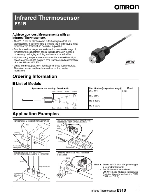
Achieve Low-cost Measurements with an Array Infrared Thermosensor.•The ES1B has an electromotive output as high as that of athermocouple, thus connecting directly to the thermocouple inputterminal of the Temperature Controller is possible.•Four temperature ranges are available to cover a wide range oftemperature measurement needs, including those in the foodprocessing, packaging, molding, and electronics industries.•High-accuracy temperature measurement is ensured by a high-speed response of 300 ms (for a 63% response) and an indicationreproducibility of ±1% PV.•Unlike thermocouples, the Thermosensor does not deteriorate.Therefore, stable, real-time temperature control can bemaintained.Ordering Information■List of ModelsInfrared Thermosensor ES1B12Infrared Thermosensor ES1BSpecifications■Ratings/CharacteristicsNote:1.Based on characteristics of K-type thermocouple and radiation rate of 0.9.2.The accuracy is given as the change in temperature from any reference temperature of the sensing object. For example, if the reference temperature is 50°C, the accuracy at 55°C would be ±2% PV or ±2°C, whichever is larger and the accuracy at 60°C would be ±4% PV or ±4°C, whichever is larger.ConnectionsItemES1BPower supply voltage 12/24 VDCOperating voltage range 90% to 110% of the power supply voltage Current consumption 20 mA max.Measuring temperature range 10 to 70°C, 60 to 120°C, 115 to 165°C, 140 to 260°CAccuracy (See note 1.)±5°C (See note 2.)±2% PV or ±2°C, whichever is larger±10°C (See note 2.)±4% PV or ±4°C, whichever is larger ±30°C (See note 2.)±6% PV or ±6°C, whichever is larger ±40°C (See note 2.)±8% PV or ±8°C, whichever is largerReproducibility ±1% PV or ±1°C, whichever is larger Temperature drift0.4°C/°C max.Sensing distance vs. sensing diameter 1:1 typ.Measurement wavelength 6.5 to 14.0 µm Receiver element ThermopileResponse speed Approximately 300 ms at response rate of 63%Output impedance 1 to 4 k ΩOperating temperature −25°C to 70°C (with no icing or condensation)Allowable ambient humidity 35% to 85%Vibration resistance (destruction)98 m/s 2 for 2 hours each in X, Y , and Z directions at 10 to 55 Hz Shock resistance (destruction)300 m/s 2 for 3 times each in X, Y , and Z directions Casing material ABS resin Degree of protection IP65Weight Approx. 120 gCableCompensating conductor: 3 mPVC-covered cable with a shield wire resisting 70°CInfrared Thermosensor ES1B3DimensionsNote:All units are in millimeters unless otherwise indicated.Adjustment MethodsAdjust the Thermosensor as described below before using it.Adjust the Thermosensor according to the conditions of the sensing object and characteristics of the Temperature Controller.Offset Compensation for Target Value with Input Shift FunctionGain and Offset Compensation with Two-point Shift FunctionES1B4Infrared Thermosensor ES1B■One-point Input ShiftPreparations•Set a temperature input range that is suitable for the input specifications of the Infrared Thermosensor.•Prepare a thermometer to measure the temperature of the sensing object as shown in figure 1, below.Configuration for Offsetting the Infrared Thermosensor Input (Figure 1)Example for the E5CN1.Adjust the temperature of the sensing object in the configuration shown in figure 1 to near the set point. We will assume that the temperature indicated on the thermometer is the actual temperature of the sensing object.2.Check the temperature C of the sensing object and thetemperature A indicated on the Controller and set both the upper-limit and lower-limit temperature input settings to the following value:T emperature C (sensing object) − T emperature A (Controller)3.Check the temperature C of the sensing object and thetemperature A indicated on the Controller again. If they are about the same, then setting the offset has been completed.Diagram of One-point Input Shift■Two-point Input ShiftUse a two-point input shift to output more accurate display values than is possible with a 1-point input shift.PreparationsRefer to the preparations for a one-point input shift.1.The input value is shifted at two points: near room temperature and near the set point. T o do so, first check the temperature C of the sensing object and the temperature A indicated on theController at both near room temperature and near the set e the following formulas to calculate the upper-limittemperature input and lower-limit temperature input settings based on the values checked above.Diagram of Two-point Input ShiftLower-limit Temperature Input SettingUpper-limit Temperature Input Setting3.Set both the upper-limit and lower-limit temperature input settings and then check the temperature C of the sensing object and the temperature A indicated on the Controller both near room temperature and near the set point.4.Although here we have used two points, near room temperature and near the set point, accuracy can be increased even further by using another point within the measurement temperature rangeother than the set value instead of room temperature.insl =YL −Y1×{(X2−Y2)−(X1−Y1)}+(X1−Y1)Y2−Y1insh =YH −Y1×{(X2−Y2)−(X1−Y1)}+(X1−Y1)Y2−Y1Infrared Thermosensor ES1B5Example for the E5CNIn this example, the ES1B is used between 140 and 260°C. Here, the set point lower limit, YL, would be 0°C and the set point upper limit, YH, would be 260°C in formulas 1 and 2. The temperatures of the sensing object are checked next.The offset values can be calculated as shown below when theController display Y1 is 40°C for a room temperature X1 of 25°C and when the Controller display Y2 is 105°C for a set point temperature X2 of 110°CUpper-limit Temperature Input SettingLower-limit Temperature Input Settinginsl =0−40×{(110−105)−(25−40)}+(25−40)105−40= −27.3 (°C)insh =260−40×{(110−105)−(25−40)}+(25−40)105−40= 52.7 (°C)PrecautionsPrecautions for Safe Usee the ES1B only within the ranges specified by itsspecifications and ratings.2.Be sure to correctly wire the input sensor leads to the properpositive and negative terminals.3.Do not use the product in the following locations:•Locations subject to icing or condensation.•Locations subject to excessive shocks or vibration.•Locations subject to dust or corrosive gases.•Locations subject to extreme temperature changes or direct sunlight.•Locations subject to water splashing or oil contact.Precautions for Correct Use1.The thermocouple output and power supply are not isolated.Make sure that unwanted circuit paths are not formed with the equipment or device that is connected to the product.2.To prevent inductive noise, wire the product separately from high-voltage sources and power lines carrying large currents. Alsoavoid parallel wiring or shared wiring paths with power lines.3.Do not allow the filter to become soiled. Use air blow or use a thincotton swab to clean the filter.1. Installation•Select a place where the emissivity is high for measuring the target. If necessary, use black spray or black tape.•Use the supplied locknuts to fix the ES1B securely in place. Tighten to a torque of 0.5 N·m max.•When measuring a high-temperature object, use a shield or similar protection to prevent the temperature of the ES1B from rising. 2. Connection•Connect to the green output lead wire (+), white output lead wire (−), orange power supply lead wire (+), and shield power supply wire (−).•To measure the temperature difference between two locations, use two isolated power supplies.3. Adjustment•The output impedance of the ES1B is 1 to 4 kΩ. Normally, current leaking to the ES1B from the burnout detection circuit of the temperature controller will offset the measured temperature in a range extending from several degrees to several tens of degrees. When using a controller equipped with an input shift function, use the input shift function to compensate for this offset error in the vicinity of the measuring temperature. For details on this compensation, see Input Shift Method below and the user's manual of the controller being used.•If the length of a lead wire must be extended, use a K thermocouple compensating conductor for the output lead wires (+, −), and standard copper wire for power supply leads (+, −).•Do not bend lead wires repeatedly.4. Cleaning•Do not use paint thinner or the equivalent for cleaning. Use standard grade alcohol.If this product should malfunction and cease to provide correct output, property damage may occur to the equipment or device that is connected to it. To prevent this, provide additional safety measures by also connecting the equipment or devices to a separate alarm system that will warn operators of temperature rises.6Infrared Thermosensor ES1BInfrared Thermosensor ES1B78In the interest of product improvement, specifications are subject to change without notice.ALL DIMENSIONS SHOWN ARE IN MILLIMETERS.To convert millimeters into inches, multiply by 0.03937. T o convert grams into ounces, multiply by 0.03527.Cat. No. H127-E1-01OMRON CorporationIndustrial Automation CompanyIndustrial Devices and Components Division H.Q.Measuring Components Department Shiokoji Horikawa, Shimogyo-ku,Kyoto, 600-8530 JapanT el: (81)75-344-7080/Fax: (81)75-344-7189Printed in Japan 0504-2M (0504) (O)Warranty and Application ConsiderationsWARRANTYOMRON's exclusive warranty is that the products are free from defects in materials and workmanship for a period of one year (or other period if specified) from date of sale by OMRON.OMRON MAKES NO WARRANTY OR REPRESENT ATION, EXPRESS OR IMPLIED, REGARDING NON-INFRINGEMENT, MERCHANT ABILITY , OR FITNESS FOR P ARTICULAR PURPOSE OF THE PRODUCTS. ANY BUYER OR USERACKNOWLEDGES THAT THE BUYER OR USER ALONE HAS DETERMINED THAT THE PRODUCTS WILL SUIT ABL Y MEET THE REQUIREMENTS OF THEIR INTENDED USE. OMRON DISCLAIMS ALL OTHER WARRANTIES, EXPRESS OR IMPLIED.LIMITATIONS OF LIABILITYOMRON SHALL NOT BE RESPONSIBLE FOR SPECIAL, INDIRECT, OR CONSEQUENTIAL DAMAGES, LOSS OF PROFITS, OR COMMERCIAL LOSS IN ANY WAY CONNECTED WITH THE PRODUCTS, WHETHER SUCH CLAIM IS BASED ON CONTRACT, WARRANTY , NEGLIGENCE, OR STRICT LIABILITY .In no event shall the responsibility of OMRON for any act exceed the individual price of the product on which liability is asserted.IN NO EVENT SHALL OMRON BE RESPONSIBLE FOR WARRANTY , REP AIR, OR OTHER CLAIMS REGARDING THE PRODUCTS UNLESS OMRON'S ANAL YSIS CONFIRMS THA T THE PRODUCTS WERE PROPERL Y HANDLED, STORED, INSTALLED, AND MAINTAINED AND NOT SUBJECT TO CONT AMINATION, ABUSE, MISUSE, OR INAPPROPRIATE MODIFICA TION OR REPAIR.SUITABILITY FOR USEOMRON shall not be responsible for conformity with any standards, codes, or regulations that apply to the combination of products in the customer's application or use of the products.T ake all necessary steps to determine the suitability of the product for the systems, machines, and equipment with which it will be used.Know and observe all prohibitions of use applicable to this product.NEVER USE THE PRODUCTS FOR AN APPLICATION INVOLVING SERIOUS RISK TO LIFE OR PROPERTY WITHOUT ENSURING THA T THE SYSTEM AS A WHOLE HAS BEEN DESIGNED TO ADDRESS THE RISKS, AND THAT THE OMRON PRODUCTS ARE PROPERL Y RATED AND INST ALLED FOR THE INTENDED USE WITHIN THE OVERALL EQUIPMENT OR SYSTEM.CHANGE IN SPECIFICATIONSProduct specifications and accessories may be changed at any time based on improvements and other reasons. Consult with your OMRON representative at any time to confirm actual specifications of purchased product.DIMENSIONS AND WEIGHTSDimensions and weights are nominal and are not to be used for manufacturing purposes, even when tolerances are shown.。
E+E Elektronik EE160 建筑自动化环境湿度和温度传感器说明书

requirements» K nockout for ½” conduit fittingExternal mounting holes Easy and fast mounting withlectronics protected against construction site pollutionBayonet screws »O pen/close with a ¼ rotationEncapsulated electronics Mechanical protection Electronics on the underside of the board ptimum protection against mechanical Protected sensor surface and solder pads Tested according to automotive standard IP65 / NEMA 4EnclosureBACnet is a registered trademark of ASHRAE. ASHRAE does not endorse,approve or test products for compliance with ASHRAE standards. Compliance of listed products to the requirements of ASHRAE Standard 135 is the responsibility of BACnet International (BI). BTL is a registered trademark of BI.Test report according to DIN EN 10204 – 3.1Ordering GuideMODELOUTPUTPASSIVE T-SENSOR 1)TYPE FILTERhumidity + (HT)0-10 V(3x)Pt 100 DIN A (A)wall mount (PA)membrane (B)temperature4-20 mA (6x)Pt 1000 DIN A (C)duct mount (PB)RS485(x3)NTC 10k(E)Ni1000, TK6180 (J)none(x)EE160-OUTPUT SCALINGSCALING 2)UNITtemperature(Tx)°C°Fmetric(M) -20...80 (024) 32...122 (076)non-metric (N)-40...60 (002)-40...140 (083) -10...50 (003) 0...140 (085) 0 (50)(004)20 (120)(015)PROTOCOLBAUDRATEPARITYSTOPBITSUNITModbus RTU 3) (1)9600 (A)odd (O) 1 stopbit (1)metric(M)BACnet MS/TP 4)(3)19200(B)even(E) 2 stopbit (2)non-metric(N)38400 (C)no parity (N)576005) (D)768005) (E)1152005)(F)Hardware configurationAnalogue outputs setupDigital interface setup1) Only with output 3x, 6x / T-sensor details see /R-T_Characteristics 2) Other scaling upon request3) Modbus Map and setup instructions: See User Guide and Modbus Application Note at /EE1604) Product Implementation Conformance Statement (PICS) available at /EE1605) Only for BACnetRecommended mounting scConduit adaptCable adap~55~2.16“Ø 12Ø 0.47“60 ±0.32.36 ±0.11“Ø > 16Ø > 0.63“60.24“90 ±0.33.54 ±0.11“Ø > 13Ø > 0.51“~205~8.07“1013.98“190.75“461.81“50.2“GASKET90 ±0.33.54 ±0.11“80.63.17“341.34“341.34“Ø 12Ø 0.47“50.2“Dimensions (mm/inch)Accessories (see data sheet …Accessories“)Product configuration software EE-PCS (free download: /EE160)Power supply adapterV03Protection cap for 12 mm probeHA010783USB configuration adapter for EE160-HTx3 (RS485)HA011066Product configuration adapter for EE160-HT3x/6x (analogue output)see data sheet EE-PCAEE160-HT6xAPAB-Tx003MModel: humidity + temperature Output: 4-20 mA Passive T-Sensor: Pt 100 DIN A Type: wall mount Filter: membrane Output scaling: temperature Scaling: -10...50 °C Unit: metricEE160-HTx3xPBB-1AE1NModel: humidity + temperature Output: RS485Type: duct mount Filter: membrane Protocol: Modbus RTU Baudrate: 9600Parity: even Stopbits: 1Unit: non-metricOrder Examples。
温度传感器使用说明
Executi ng division : Responsible division : Document type : Confidentiality status :HCN NVPTechnical Documentation InternalPrepared :Document state :08.02.2006 Czernietzki (NVP)Technology Transfer HCN PreliminaryChecked :09.02.2006 Czernietzki (NVP)FNC System BusinessThermistorsApproved :File:Revision :Language :Pages :09.02.2006 Czernietzki (NVP) TD-Thermistors-en-R001 001 en 1/19This document and its contents are the property of Hoppecke or its subsidiaries. This document contains confidential proprietary information. The reproduction,Document administration 文件管理Document History 文件记录VersionDateResponsibleReason of change001 08.02.2006 Czernietzki First release of the document.Change justifiable 变更审核Hans-Peter Czernietzki NVPPreparing , Checking , ApprovingLewis Liu HCN QS Preparing , Checking , ApprovingDocument generated with following tools 使用下列工具编写文件:WORD 200 <Grafic tool>Content 目录1 Overview Thermistors........................................................................................................................................................................2 1.1 General.....................................................................................................................................................................................2 1.2 NTC Thermistors.....................................................................................................................................................................4 1.3 PTC Thermistors......................................................................................................................................................................5 1.4 Lead wire configurations..........................................................................................................................................................6 1.5 Available temperature probe....................................................................................................................................................8 1.6 Available connection cables.....................................................................................................................................................8 2 Designs...............................................................................................................................................................................................9 2.1 Stainless steel block version.....................................................................................................................................................9 2.2 Electrolyte version...................................................................................................................................................................9 2.3 Connection cables..................................................................................................................................................................10 2.3.1 Two wire connection 414 220 0802.............................................................................................................................10 2.3.2 Four wire connection 414 220 0804............................................................................................................................10 2.3.3 Connection clamp........................................................................................................................................................10 2.4 Temperature curve PT100B...................................................................................................................................................11 2.5 Temperature curve NTC10K..................................................................................................................................................11 2.6 Technical data NTC10K.........................................................................................................................................................11 3 Attachments......................................................................................................................................................................................11 3.1 Drawing 2BZ60287-01..........................................................................................................................................................11 3.2 Drawing 3BZ60731-01..........................................................................................................................................................11 3.3 Drawing 2BZ60287-02..........................................................................................................................................................11 3.4 Drawing 3BZ60407-01..........................................................................................................................................................11 3.5 Drawing 3BZ60732-01..........................................................................................................................................................11 3.6 Drawing 3BZ60407-02. (11)1 Overview Thermistors电热调节器简介1.1 General总则Resistance elements come in many types conforming to different standards, capable of different temperature ranges, with various sizes and accuracies available. But they all function in the same manner: each has a pre-specified resistance value at a known temperature which changes in a predictable fashion. In this way, by measuring the resistance of the element, the temperature of the element can be determined from tables, calculations or instrumentation. These resistance elements are the heart of the RTD (Resistance Temperature Detector or short: Thermistor). Generally, a bare resistance element is too fragile and sensitive to be used in its raw form, so it must be protected by incorporating it into an housing.电阻元器件满足不同的标准,能够适用不同的温度范围,可满足多种尺寸和精度要求。
温度传感器设置参数指南说明书
Cód.ParámetroU.M.TipoMín.Máx.VALOR/2Estabilidad de la medida -C 1154/3Deceleración visualización sonda-C 0150/4Sonda virtual-C 01000/5Selección °C o °F (0=°C, 1=°F)flag C 010/6Punto decimal (0=si 1=no)flag C 011/tI Visualización sobre el display -C 171/tE Visualización en terminal externo-C 060/P Selección tipo de sonda -C 020/A2Configuración de la sonda 2-C 042/A3Configuración de la sonda 3-C 040/A4Configuración de la sonda 4-C 040/A5Configuración de la sonda 5-C 040/c1Calibración de la sonda 1°C/°F C -20200/c2Calibración de la sonda 2°C/°F C -20200/c3Calibración de la sonda 3°C/°F C -20200/c4Calibración de la sonda 4°C/°F C -20200/c5Calibración de la sonda 5°C/°FC-2020St Set point (punto de consigna)°C/°F F r1r2-23rd Diferencial regulador°C/°F F 0.120 3.0rn Zona neutra°C/°F C 0604rr Diferencia inverso para control con zona neutra°C/°F C 0,1202r1SET mínimo admitido °C/°F C -50r2-23r2SET máximo admitido °C/°F C r120020TABLA DE PARÁMETROSCAREL: PUIFI0006 (MEMBRANA / ARMARIOS BT)/ PARÁMETROS SONDAr PARÁMETROS REGULADORr3Modalidad de funcionamientoflag C 020r4Variación automática del SET POINT nocturno °C/°F C -20200r5Habilitación de la monitorización de la temp.flag C 011rt Intervalo de monitorización de la temperaturahoras F 09990rH Máxima temperatura leída °C/°F F 000rLMínima temperatura leída°C/°FFc0Ret. arr. comp. y vent. en el mom. del encendido min C 0151c1Tiempo mínimo entre encendidos sucesivos min C 0151c2Tiempo mínimo de OFF del compresor min C 0150c3Tiempo mínimo de ON del compresormin C 0150c4Arranque forzado min C 01000cc Duración del ciclo continuohoras C 0150c6Tiempo exclusión de alarma después del ciclo continuohoras C 02502c7Tiempo máximo de Pump-Downs C 09000c8Retr. arr. comp. después de la ap. de la válvula PD s C 0605c9Habilitación función de autoarranque con func. en PDflag C 010c10Selección Pump-Down de tiempo o presiónflag C 010c11Retraso 2º compresorsC250d0Tipo de desescarche (0=resis. 1=gas 2=agua 3=gas a tiempo)flag C 041dI Intervalo entre dos desescarches horas F 02503dt1Temperatura fin desescarche evaporador °C/°F F -5020020dt2Temperatura fin desescarche evaporador auxiliar°C/°F F -5020020dt3Temperatura fin desescarche sonda 3°C/°F F -502004dP1Duración máx. del desescarche evaporador min F 125030dP2Duración máx. del desescarche evap. auxiliar min F 125030d3Retraso de activación del desescarche min C 02500d4Desescarche a la conexión del equipo flag C 010d5Retraso del desescarche a la conexion min C 02500d6Bloqueo del display durante el desescarche -C 021ddTiempo de goteo después del desescarcheminF154c PARÁMETROS COMPRESORd PARÁMETROS DE DESESCARCHEd8Exclusión alarmas después del desescarche horas F 02501d8d Tiempo exclusión de alarma tras puerta abierta min C 02500d9Prioridad del desescarche frente protecciones compresorflag C 010d/1Visualización de la sonda de desescarche °C/°F F 000d/2Visualización de la sonda de desescarche °C/°F F 000dC Base de los tiempos para desescarche flag C 010dC1Base de los tiempos para retardo de alarmas flag C 010d10Tiempo de funcionamiento del compresor min C 02500d11Umbral de temperatura para tiempo de funcionamiento°C/°F C -2020 1.0d12Desescarches avanzados -C 030dn Duración nominal del desescarche -C 110065dHFactor proporcional variación de ‘dI’-C10050A0Diferencial alarmas y ventiladores°C/°F C 0.120 1.0A1Tipo de umbral ‘AL’ y ‘AH’flag C 010AL Umbral de alarma de baja temperatura °C/°F F -5020010AH Umbral de alarma de alta temperatura °C/°F F -5020010Ad Retraso alarma baja y alta temperatura min F 0250120A4Configuración de la entrada digital 1-C 0120A5Configuración de la entrada digital 2-C 0120A6Bloqueo del compresor por alarma externa min C 01000A7Retraso de detección alarma externa min C 02500A8Habilitación alarmas ‘Ed1’ y ‘Ed2’ flag C 010A9Configuración salida digital 3flag C 0140Ado Configuración modo luz puerta flag C 010Ac Alarma alta temperatura del condensador °C/°F C 0.020070.0AE Difer. de la alarma de alta temp. cond.°C/°F C 0.12010Acd Retraso alarma alta temp. del condensadormin C 02500AF Tiempo apagado con sensor de luzseg C 02500ALF Umbral de alarma antihielo °C/°F C -50200-5AdFRetardo alarma antihielosegC250A PARÁMETROS DE ALARMAF0Control ventiladorflag C 022F1Temperatura encendido ventilador °C/°F F -50200 5.0F2Ventilador OFF con compresor OFFflag C 011F3Ventiladores en desescarche flag C 011Fd Ventiladores apagados después del goteo flag F 0150F4Temperatura ventilador condensador OFF°C/°F C -5020040F5Diferencial ventilador condensador°C/°FC0,1205Pw Contraseña -C 020022H0Dirección serial -C 02071H1Funcionalidad del relé 4flag C 0133H2Deshabilitación teclado/Infrared flag C 061H3Código habilitación telecomando -C 02550H4Deshabilitación zumbador flag C 010H5Funcionalidad del relé 5-C 0133H6Bloqueo teclas -C 025532H7Selección tecladoflag C 010H8Luz o salida aux conmutada con control horario-C 010H9Variación set point con control horario-C 010HPr Perfil de impresión-C 0150Hdn Num conjuntos de parámetros predeterminados disponibles-C 060Hdh Desfase de resistencia antivaho°C/°F C -502000HrL Control remoto de estado de relé de luz principal -C 010HrA Control remoto de estado de relé AUX principal -C 010HSA Control remoto de alarmas de controladores en ud principal-C 010In Tipo de unidad-C 060s_cLrH Orden baja humedad relativa-C 010s_cAUX Orden activar AUX -C 010s_cLUX Orden activar luz -C 010s_cONOFFOrden controlador ON/OFF-C1F PARÁMETROS VENTILADOR (solo para el modelo C)H OTRAS PREDISPOSICIONES。
欧切斯EUS01光传感器说明书
上海欧切斯实业有限公司
产品介绍
面对日益严重的能源和环境危机,建筑商、建筑师和照明专家逐渐把日光照明作为照明的的主要来 源,并且适当的光线可以增加舒适感。
为了充分利用光线一体化,建筑物应该根据外部的光线自动关闭或调节灯具亮度。这就叫做“光线 采集”。
EUS01 为光线采集提供了一种简单而有效的解决方案。可以直接连接到 1-10V 信号接口,使用光电 管来测量外部光线亮度并自动计算所需灯光亮度,然后将信号传输给 1-10V 调光控制器(镇流器或 LED 驱动)。1-10V 调光控制器根据接收到的信号调节输出亮度。
自然光线充足时,即 自然光线不足时,有 灯具根据外部自然光亮度 100%亮度输出,或调光维持预设 使有人进入感应区, 人进入感应区,灯具 亮度水平。 灯具也呈关闭状态。 自动开启。
当自然光线充足时,灯具立刻关 自然光线不足,当延时结束后,若没有人进入感应区,灯具将调至
闭,即使有人进入感应区。
待机亮度,待机时间结束后,关闭灯具。
设置
设置
为达到最佳效果,目标亮度水平应为灯具总照度的 40%-80%。
能够自动关 断 否 是 是
EUS01 产品说明书 V01.1
4
产品特点
z 节能而不影响舒适 z 通过外部光线控制 z 直接连接到 1-10V 信号接口 z 用户可以通过电位器设定目标亮度
EUS01 产品说明书 V01.1
1
EUS01+1-10V 调光控制器(任意品牌)
上海欧切斯实业有限公司
根据自然光亮度,灯具 100%亮度输出,或调光维持预设亮度 自然光线充足时,灯具 如有需要,用户
总结
EUS01 + 1-10V调光控制器 EUS01 + 微波感应开关 + 1-10V调光控制器 EUS01 +智能调光微波感应器 + 1-10V 调光 控制器
阿尔法冷 ES 高流速度传感器说明书
The Alphacool ES "HighFlow" with tacho signal is a sensor for watertemperature and water flow that can be easily integrated into any water circuit.•For Hose and HardTube systems •Can be positioned as required •Continuous measurement1x ES flow and temperature indicator V. 1.000 // 11.2023Alphacool ES flow and temperature indicator "HighFlow"with RPM-SignalAlphacool article number: 17558The Alphacool ES "HighFlow" with tacho signal is a sensor for water temperature and water flow that can be easily integrated into any water circuit.Integration made easyThe Alphacool ES "HighFlow" flow and temperature sensor is very compact and can be integrated into any water circuit thanks to its two G1/4" internal threads. It does not matter whether the system is equipped with soft tube or HardTubes. Simply screw the appropriate connections to the sensor and then mount it at any position in the loop.Temperature sensorA classic NTC 10 kOhm thermistor is used as the sensor. The readable temperature range is between -40 and 125°C. The cable is 43.5 cm long and terminates in a typical 2-pin connector. Many mainboards now offer direct connection options for such sensors. Please check the manual of your mainboard. Of course, there are also various external controllers that offer a connection for the sensor (controller with NTC connection). A corresponding readout device is not included in the scope of delivery.Flow sensorThe flow sensor enables continuous measurement of the water flow within. The sensor has a 42cm sensor cable included in the scope of delivery and corresponding connectors.Download kOhm Sensor Table AlphacoolDrawing。
温度显示仪屹思达ESTDI-1说明书
温度显示仪屹思达ESTDI-1说明书一、概述本仪表由单片机控制,具有热电阻、热电偶等多种信号自由输入,五种输出方式只须插上相应模块即可,正反控制任意设置;提供了四种报警方式;手动自动切换,主控有两位式、PID两种控制方式,在各种不同的系统上,经仪表自整定的参数大多数能得到满意的控制效果,具有无超调,抗扰动性强等特点。
二、主要技术指标1、基本误差:±0.5%F.S±1个字2、冷端补偿误差:≤±2.0℃3、采样周期:0.5秒4、控制周期:继电器输出时的控制周期为2~120秒可调,其它为2秒。
5、继电器触点输出:AC220V/5A(阻性负载)或AC220V/0.3A(感性负载)。
6、驱动固态继电器信号输出:驱动电流≥15mA,电压≥9V。
7、驱动可控硅脉冲输出:幅度≥3V,宽度≥40us的移相或过零触发脉冲。
8、连续PID调节模拟量输出:0~10mA(负载500±200Ω), 4~20mA(负载250±100Ω),或0~5V(负载≥100kΩ), 1~5V(负载≥100kΩ)。
9、电源:AC85V~242V(开关电源), 50/60Hz,或其它特殊定货。
10、工作环境:温度0~50.0℃,相对湿度不大于85%的无腐蚀性气体及无强电磁干扰的场所。
三、设置1、下限偏差告警设置:按SET键选择显示“SLP”,绿色显示屏显示该项参数的数值,选择移位、递增、递减键设置或修改该项参数。
该参数表示告警点低于主控设定点的相差值。
2、上限偏差告警设置:按SET键选择显示“SHP”,绿色显示屏显示该项参数的数值,选择移位、递增、递减键设置或修改该项参数。
该参数表示告警点高于主控设定点的相差值。
3、比例范围设置:按SET键选择显示“P”,绿色显示屏显示该项参数的数值,选择移位、递增、递减键设置或修改该项参数。
“P”值越大,温控器的主控继电器输出的灵敏度越低,“P”值越小,温控器的主控继电器输出的灵敏度越高。
- 1、下载文档前请自行甄别文档内容的完整性,平台不提供额外的编辑、内容补充、找答案等附加服务。
- 2、"仅部分预览"的文档,不可在线预览部分如存在完整性等问题,可反馈申请退款(可完整预览的文档不适用该条件!)。
- 3、如文档侵犯您的权益,请联系客服反馈,我们会尽快为您处理(人工客服工作时间:9:00-18:30)。
4~20mA/-50~+500℃ * 负载阻抗300Ω以下 分辨率:约10000 (输出温度范围可用编程器修改)
DC12~24V
电源电压的95~105%
40mA以下(但连接编程器时为45mA以下)
2m±10cm
±(2+0.1%输出范围)℃以内 (测量温度0~+200℃) ±(1% rdg+0.1输出范围)℃以内 (+200~+1,000℃) (环境温度23℃、湿度55%、辐射率1.00)
高温用(0~+1,000℃)机种。 • 还增加了测温距离500mm、1,000mm的长距离型。 • 使用另售的编程器可更改温度的监测
及辐射率、移动平均功能、输出范围。 (照片为在ES1本体上安装编程器)
⬉ᄤ⏽఼Z 种类
⬉ᄤ⏽఼ NEO
⬉ᄤ⏽఼R
⬉ᄤ⏽఼K
⬉ᄤ⏽఼S
类别 高温用 中低温用 中温用
474 非接触温度传感器 ES1
连接例
ᢳ䕧ߎ
ࠊ఼ᰒ冫఼
外形尺寸
ES1-LP3 ES1-LP10 ES1-LW50H ES1-LW50
⬉⑤ 㑶
ᢳ䕧ߎ݀݅ッ ˄ሣ㬑˅
⬉⑤
(1)
32
(11) 53
38 20.5
0.5 ܝᄺ㋏䚼
★附有设置盒。 附带确定视野用的设置盒。 (只限ES1-LP3、 LP10)
温度一样。
476 非接触温度传感器 ES1
规格
功能
与本体的连接 显示更新 消耗电流 使用温度范围 保管温度范围 显示温度范围 重量
型号 ES1-PRO
测量值、设定值的显示,设定值的变更(放射率ε,输出范围 MAX,输出范围MIN,移动平均数据数),电流输出测试(零输 出,满刻度输出),出错信息(出错显示,数据闪烁,OVER闪 烁,℃闪烁) 带3P迷你插头,2m电缆 2次/秒 5mA以下 0~+55℃ -20~+55℃ 本体为ES1-LW50H/-LW100H时:-70~+1,050℃ 本体为ES1-LP3/-LP10/-LW50/-LW100时:-70~+550℃ 约140g
●ES1-LP3的场合
φ32.4 φ10.3 φ3
ES1-LP3
●ES1-LW50H、ES1-LW50的场合
φ140
φ72
30 50
100
●ES1-LP10的场合
φ36
φ8.0 φ10.6
ES1-LP10
2,000
●ES1-LW100H、ES1-LW100的场合
φ55
φ45
φ35
⬉ᄤ⏽఼S
(单位 :mm)
温度:0~+55℃、 湿度:35~85%(不结冰、凝露)
温度:-20~+55℃、湿度:35~85%(不结冰、凝露)
10~55Hz 20m/s2 3轴方向 10min
Байду номын сангаас
10~55Hz 单振幅0.75mm 3轴方向 2h
IP-□2(不包括镜头)
CE标记
L:102、W:32、H:40mm L:64、W:32、H:40mm
非接触温度传感器
ES1
相关信息 商品选择 …………………… 221
共通注意事项 ……………… 236 技术指南 …………………… 481 用语说明 …………………… 485
⬉ᄤ⏽఼
ଚક䗝ᢽ ݅䗮⊼ᛣџ乍
不接触工件就能测量温度。 实现了无损伤、卫生且 有效的温度管理。
• 备有小光斑直径φ3mm和φ8mm的2种类型。 • 重现性±0.5℃、响应速度0.4秒(95%)和高精度、高速度测量。 • 除了原有的中温用(0~+500℃),还增加了中低温(-50~+500℃)、
(电缆除外)
(电缆除外)
L:102、W:32、H:40mm L:64、W:32、H:40mm
(电缆除外)
(电缆除外)
约150g
约120g
约150g
约120g
安装配件、使用说明书
* 出厂时, 0~+500℃、 -50℃必须用ES1-PRO修改范围。
ES1-LP3
中温用 ES1-LP10
4~20mA/0~+500℃ 负载阻抗300Ω以下 分辨率:约10000 (输出温度范围可用编程器修改)
ES1 䴲㾺Ӵᛳ఼
4̚20mA䕧ߎ
⬉ᄤ⏽఼ ⏽ᑺ䇗㡖఼
E5CN-LǃE5AN-LǃE5EN-L
᭄ᄫ䇗㡖Ҿ E5AKǃE5EKǃE5CKǃE5ARǃE5ER
᭄ᄫ䴶ᵓҾ㸼 K3HB-XǃK3HB-SǃK3GN
示范应用
ଚક䗝ᢽ
݅䗮⊼ᛣџ乍
⬉ᄤ⏽఼Z ⬉ᄤ⏽఼
NEO
曲奇、饼干、面包的温度测定
ᴤ᭭ᆍ఼ ᧙ᢠ఼
型号 ES1-S ES1-T
᪡㆛
黑体胶带/喷雾请用于辐射率低且不明的物体的温度测量中。
辐射率低的情况下的测量 1)在想要测温的部分贴上黑色胶带(放射率0.95)。 2)将非接触温度传感器的放射率设定为ε=0.95后测量。
辐射率不明的情况下的测量 1)在要测温的部分贴上黑色胶带(放射率0.95)。 2)将非接触温度传感器的放射率设定为ε=0.95后测量。 3)撕下胶带,测量温度。将非接触温度传感器的放射率设定得和贴有胶带时的
±(2+0.1%输出范围)℃以内 (测量温度0~+200℃) ±(1% rdg +0.1输出范围)℃以内 (+200~+500℃) ±(10% rdg +2+0.1%输出范围)℃以内 (-50~0℃) (环境温度23℃、湿度55%、辐射率1.00)
1℃以内(+501~+1,000℃)、0.5℃以内(0~+500℃)
测定温度范围 0~+1,000℃ -50~+500℃ *1 0~+500℃
标的尺寸 *2 φ35mm(距离1,000mm) φ40mm以下(距离500mm) φ35mm(距离1,000mm) φ40mm以下(距离500mm) φ3mm(距离30mm) φ8mm(距离100mm)
*1. 交货时0~+500℃、 -50℃需要ES1-PRO修改范围。 *2. 是基于90%的能量限制的数值。实际对象体大小必须相当于该尺寸的1.5倍以上。
䱨⛁ᴤ᭭
㒣⌢ൟ
ഫൟ PLCऩܗൟ
选装件
●黑体喷雾/黑体胶带
ᬃᣕ䕃ӊ
Ⳍ݇䆒
䕧ܹ䆒
黑体喷雾 :ε=0.94 (耐热温度550℃) 黑体胶带 :ε=0.95 宽50mm×10m 厚0.2mm (耐热温度180℃)
●编程器
㒓 68(W)×21(D)×90(H)mm
ᡔᴃᣛफ
名称 黑体喷雾 黑体胶带
ㅵ䘧
⒮ㄦ ♝
偀䖒
ࡴ⛁఼
测定成形机、树脂压出机等的温度 य़ߎᴎ
橡胶、树脂制传送带的温度管理 轴连接部的发热
Ćᔧ⌟䆩䚼ߚЎ 䞥ሲ⋑ܝ䴶ˈ䇋 Փ⫼䗝乍Ёⱘ 咥ᏺ✻ᇘDŽ
Ӵ䗕ᏺ
䞛ḋ
⬉ᄤ⏽఼R 干燥纤维或印刷
检查配电盘的接口疏漏
⬉ᄤ⏽఼K ⬉ᄤ⏽఼S
ᑆ➹♝
ࡴ⛁⒮ㄦ
管理装订作业的浆光温度
隔热材料的质量管理
13 14 2-M4ᦦܹ ⏅ᑺ4
ES1-LW100H ES1-LW100
(1)
32
38
φ24
20.5
0.5 ܝᄺ㋏䚼
⬉ᄤ⏽఼ (单位 :mm)
102 (11)
53
13 14
2-M4ᦦܹ(⏅ᑺ4)
ଚક䗝ᢽ
݅䗮⊼ᛣџ乍
⬉ᄤ⏽఼Z ⬉ᄤ⏽఼ NEO ⬉ᄤ⏽఼R
⬉ᄤ⏽఼K
测定视野
测量对象应在光斑直径的1.5倍以上。 测量物体的测量面积如果小于测量视野,额定温度可能发生误差。
1℃以内
0.5℃以内
±0.25℃/℃以内(0~+500℃)、±0.5℃以内(+500~+1,000℃)
±0.5℃/℃以内(-50~0℃)、±0.25℃/℃以内(0~+500℃)
0.40s以内(95%响应,移动平均数据数=1时)
出厂时设定:0.95使用编程器可修改为0.10~1.99
出厂时设定:移动平均数据数=1 使用编程器可修改为1~25
㒣⌢ൟ
φ40 ES1-LW50H ES1-LW50
500 1,000
ഫൟ PLCऩܗൟ ᬃᣕ䕃ӊ Ⳍ݇䆒
䕧ܹ䆒
φ26
ES1-LW100H
ES1-LW100
50
100 300
500 1,000 1,500 2,000
ᡔᴃᣛफ ᪡㆛
非接触温度传感器 ES1 475
䗮䖛ࠊ఼ӊⱘ䖲ˈৃᵘ៤䖥ԐѢᭈԧ⏽ᑺㅵ⧚ⱘ㋏㒳DŽ
测定精度
重现性
温度偏差
响应时间
发射率设定
移动平均功能
使用温湿度范围
保存温湿度范围
抗振
误动作 耐久
保护结构
适合标准
外形尺寸
重量 标准配件
高温用
中低温用
ES1-LW100H
ES1-LW50H
ES1-LW100
ES1-LW50
热电偶
硅
8~16mm
4~20mA/0~+1,000℃ 负载阻抗300Ω以下 分辨率:约10000 (输出温度范围可用编程器修改)
±(3+0.1%输出范围)℃以内 (测量温度0~+300℃) ±(2% rdg-3+0.1%输出范围)℃以内 (+300~+500℃) (环境温度23℃、湿度55%、辐射率1.00)
1℃以下 ±(0.2℃/℃+0.01%输出区域/℃)以内