GFSIGNET2350温度传感器操作说明书.
红外测温仪的操作指南及各模块说明
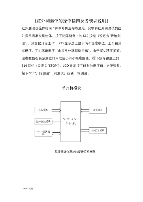
《红外测温仪的操作指南及各模块说明》红外测温仪操作指南:将单片机连接电源后,只需将红外测温仪的红外探头瞄准被测物体,按下矩阵键盘上的S13按钮(设定为“开始测温”),测温仪开始工作,LCD显示屏上显示两个温度数值,上为被测点温度,下为环境温度(由探头外环探测得出)。
由于探头精度灵敏,温度数值在稳定建立时间过后仍有小幅度跳变。
按下矩阵键盘上的S14按钮(设定为“STOP”),LCD显示按下时刻的温度值,方便读数。
按下S13“开始测温”,测温仪开始新一轮测温。
单片机模块红外测温仪系统的硬件结构框图红外测温仪系统的软件方案设计框图主程序模块:主要完成系统初始化,温度的检测,串行口通信,键盘和显示等功能。
其中系统初始化包括: 时间中断的初始化、外部中断源的初始化、串口通信中断的初始化、LED 显示的初始化。
红外测温模块:包括获取温度数据,计算温度值。
键盘扫描模块:获取按键信息,处理按键请求等。
显示模块:获取并处理相应的温度数据,通过LED数显管显示温度数据。
单片机处理模块单片机模块的工作原理是:加载相应程序的STC89C51单片机把红外测温模块传来的数据加以处理,送LED显示屏显示。
下图1是单片机处理模块的电路原理图图1 单片机处理模块电路图其复位电路如图2-1左边上部分,本单片机处理模块是通过开关手动复位的,只要在RST引脚出现大于10ms的高电平,单片机就进入复位状态,这样做的目的是便于根据实际情况而选择是否复位温度测量数据。
而此仪器的震荡电路选用的是晶体震荡电路,其具体电路如图2-1左边下部分。
采用晶体震荡电路的原因是因为它的频率稳定性好,而这正是本红外测温仪非常重要的技术要求。
单片机作为红外测温仪的核心处理部件,它关系到整个仪器的性能指标。
因此它的选择是非常重要的。
本测温仪选择的STC89C51RC单片机,下面是STC89C51RC单片机相关资料信息:STC89C51RC单片机是宏晶科技推出的新一代超强抗干扰/高速/低功耗的新一代8051单片机,指令代码完全兼容传统8051单片机,12时钟/机器周期和6时钟/机器周期可任意选择,最新的D版本部集成MAX810专用复位电路。
浸入式温度传感器
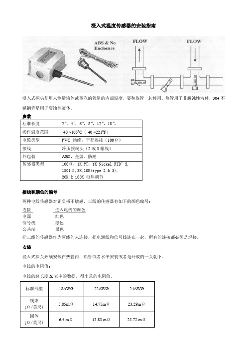
浸入式温度传感器的安装指南浸入式探头是用来测量液体或蒸汽的管道的内部温度,要和热管一起使用。
热管用于非腐蚀性液体,304不锈钢管是用于腐蚀性液体。
接线和颜色的编号两种电线传感器对正负极不敏感,三线的传感器有如下的颜色编号:连接进入电线的颜色电源红色信号线绿色公共端黑色把三线的传感器作为两线的来连接,把电源线和信号线连在一起,所有的连接都必须是焊接。
安装浸入式探头必须安装在热管内,热管或者水平安装或者是开放的一头朝下。
电线的电阻值:电线的总长度X表中的数据,得出总的电阻值。
室外照度传感器LL-ALS1E 照度传感器是用来控制人工照度,取得最好的光照效果,最大限度的节能。
LL-ALS1E 照度传感器利用光明二极管电池来测可选照明单位范围内的光照度。
提供一个线性的0~10V的输出信号。
LL-ALS1E 照度传感器是安装在户外用来测量户外光度。
性能:●连接可选择的范围●24V电源●0~10的输出参数:传感参照光敏二极管精确度+5%视野60度可切换选择:0-2000 Lux0-4000 Lux0-10000 Lux0-20000 Lux控制器机盒材料复合碳酸盐尺寸(见图)环境要求:温度:0~500CRH:0~100% 不可压缩电源供应24Vac/dc(+10%)连接3线输出0~10Vdc保护IP65重量250G产地英国三种典型的光线状态:Lux黄昏15-20 日光2000 晴天20000+光照服务能力:Lux户外最小值25外部的人行道和停车厂50工业生产流程区,仓库150最小的任务光度200总的办公区和其他区域500精细工作,机器操作,机械安装等等1500压力传感器型号:PR-274-275●100%的固态,微机电,玻璃(含硅),超稳定性能的传感器●当压力值低至+0.05`` WC(+12.5Pa)●可解决低于0.0001●高至10 PSID超压力●每个单为内有6个可供选择的范围●输送电源的电压范围很广,在12-40VDC/12-35V AC,可调节●两种补偿温度的输出,4-20mA,两线或者可选择0-5VDC/0-10VDC ●可测口径●短路或正负极颠倒时可保护●符合EMC标准EN50082-1/ EN55014/ EN60730-1GS531-CH 挂壁式氯气传感器技术简介:氯气传感器在5-20ppm氯气浓度范围的输出范围是4-20mA。
GF SIGNET 2450 压力传感器操作说明书
3.4 远方在线式安装(2450-2,2450-5)
可以选用带有 3/4in.过程连接形式的 3-8052-1 一体式接线盒,它提供了方便的接线端子,可 实现电缆在一定范围内的长度延伸。 • 接线盒含有以下组件:
• ¾ in. NPT 传感器连接形式 • 带有接线端子的电缆连接基座与盒盖 • 3-9000.392-1 液密连接件,1/2 in. NPT
传感器 • 涂上密封胶,将传感器安装在延长管段上或
防水导管上。 • 为了防止湿汽侵入/累积于管内,要在延长
管端上装电缆封盖。 • 严禁将传感器的后部牢牢封死(如用硅酮或
环氧树脂)。这样做会因大气压和/或温度 的变化而引入测量误差。 • 在此安装选项中,8050-1 与 8052-2 接线盒 很有用。
• -3X,-4X,-7X:1/2 in.由令阳螺纹
后部连接形式:
3/4 in. NPT 阳螺纹
电缆类型: 3 芯屏蔽电缆,22AWG 黑/红/白/屏蔽线
标准电缆长度:
• 2450-1X,-3X,-5X,-7X: 4.6m(15ft.)
• 2450-2X,-4X:
16cm(6in.)
传感器精度: ±1%满量程@25℃
3-8050-1 3-8052 3-8052-1 3-9000.392-1 3-9000.392-2 5523-0322
编码
159 000 679 159 000 680 159 000 683 159 000 686 159 000 905 159 000 906 159 000 024 159 000 025 159 000 682 159 000 685 159 000 907 159 000 908 159 000 026 159 000 027 159 000 681 159 000 684 159 000 909 159 000 910
Signet 2537 转轮流量计中文操作说明书
对于此传感器的早期版本,2537手册的Rev. C版本可在上的Resource Center中获得。
选择Sensors and Instrumentation,单击Archived Products,选择2537,单击Instruction Manuals。
*3-2537.090*3-2537.090 Rev. 11 03/19Signet 2537 转轮流量计中文操作说明书• English• 中文222235556677771014-152Signet 2537 转轮流量计3 Signet 2537 转轮流量计4Signet 2537 转轮流量计5Signet 2537 转轮流量计安装尺寸接线塑料传感器安装提示• 检查传感器O形圈是否有可能损坏密封的刻痕或其他损坏。
• 使用与系统兼容的非石油基的粘性润滑剂(润滑脂)润滑O形圈。
• 来回扭动传感器,将其放入安装件中,确保黄色外壳上的穿线管端口指向流向。
• 接合传感器盖的一个螺纹,然后转动传感器,直到对齐卡舌卡入安装件的槽口中。
传感器帽卡舌槽口流向润滑O型圈只有合格人员才能操作本产品的电气连接。
要使用接线端子:1. 逆时针转动黄色盖子¼圈以将其取下。
2. 卸下两个固定螺钉,然后拆下黑色盖板。
• 在将电缆连接到端子之前,请将所有电缆穿过穿线管端口。
• 接线端子适用于16-22AWG规格的导线。
• 电缆直径必须为7 mm至10 mm(0.275 in.至0.394 in.),以便在液密接头中正确密封。
3. 穿线管端口有1/2英寸NPT螺纹。
布线后,用液密穿线管接头(3-9000.392-1)或穿线管来密封端口。
• 对于穿线管的安装:• 螺纹穿线管带有½英寸NPT螺纹,可直接连接穿线管管端口。
• 对于带有ISO螺纹的穿线管,请使用接头套件随附的黑色螺纹适配器。
• 为符合NEC要求,请勿在安装中使用任何金属穿线管。
3-2537-xC-P15 in. to 8 in. 管路3-2537-xC-P0½ in. to 4 in. 管路130 mm (5.12 in.)97 mm (3.82 in.)171 mm (6.73 in.)97 mm (3.82 in.)用手将螺母拧紧到安装件上。
IWPT系列无线温度传感器操作手册说明书

|IWPT SeriesINDUSTRIAL WIRELESS PRESSURE TRANSMITTERWhilst every effort has been taken to ensure the accuracy of this document, we accept no responsibility for damage, injury, loss, or expense resulting from errors or omissions, and reserve the right of amendment without notice.Information for usersThis equipment has been tested and found to comply with the limits for a Class B device, pursuant to part 15 of the FCC Rules. These limits are designed to provide reasonable protection against harmful interference in a residential installation. This equipment generates uses and can radiate radio frequency energy, and if not installed and used in accordance with the instructions, may cause harmful interference to radio communications. However, there is no guarantee that interference will not occur in a particular installation. If this equipment does cause harmful interference to radio or television reception, which can be determined by turning the equipment off and on, the user is encouraged to try to correct the interference by one or more of the following measures:•Reorient or relocate the receiving antenna•Increase the separation between the equipment and receiver•Connect the equipment into an outlet on a circuit different from that which the receiver is connected•Consult the dealer or an experienced radio/TV technician for helpCaution: To satisfy FCC RF Exposure requirements for mobile and base station transmission devices, a separation distance of 20cm or more should be maintained between the antenna of this device and persons during operation. To ensure compliance operation at closer than this distance is not recommended. The antenna used for this transmitter must not be co-located or operating in conjunction with any other antenna or transmitter. No other antenna may be used with this equipment other than the PCB antenna supplied with this equipment.This document may not be reproduced in any way without the prior written permission of the company.Cynergy3 Components Ltd7 Cobham Road, Ferndown Industrial Estate, WimborneDorset BH21 7PE, United KingdomTel:+44(0)1202897969,email:******************CONTENTS1.INTRODUCTION _______________________________________________________ 21.1 SAFETY INFORMATION _____________________________________________________ 21.2HARDWARE FEATURES ____________________________________________________ 22.UNPACKING__________________________________________________________ 33.PRODUCT IDENTIFICATION LABEL _____________________________________ 35.SETTING UP THE IWPT WIRELESS PRESSURE TRANSMITTER ___________ 46.TROUBLE-SHOOTING GUIDE__________________________________________ 67.SYSTEM PART NUMBERS______________________________________________ 78.SPECIFICATIONS & CERTIFICATIONS__________________________________ 9 1. INTRODUCTION1.1 Safety InformationThis manual contains information that must be observed in the interest of your safety and to avoid damage to assets. Please read this manual before installing and commissioning the device and keep the manual in an accessible location for all users.Contains FCC ID: W70MRF24J40MDMECaution: To satisfy FCC RF Exposure requirements for mobile and base station transmission devices, a separation distance of 20cm or more should be maintained between the antenna of this device and persons during operation. To ensure compliance operation at closer than this distance is not recommended. The antenna used for this transmitter must not be co-located or operating in conjunction with any other antenna or transmitter. No other antenna may be used with this equipment other than the PCB antenna supplied with this equipment.Please see the Certifications section for more information on RF Exposure Compliance 1.2 Hardware FeaturesThe IWPT range of Wireless Pressure Transmitters has been designed to measure the pressure of the medium connected and transmit the value to one of the IWR range of receivers where the value can be outputted as either a 4-20 mA or 1-5 V dc signal.The IWR-1 has a single output and the IWR-5 has five outputs, each of which can be linked to an IWPT transmitter. The IWPT pressure transmitter works on the license-free 2.4 GHz band.Ranges of up to 500 m are possible using the standard transmitter and receiver unit with the optional 3dBi antenna giving a range of up to 750 m. The transmitter is powered by a 3.6V lithium cell and care must be taken to insert the battery in the correct polarity.2. UNPACKINGThe instrument should be carefully inspected for signs of damage that may have occurred in transit. In the unlikely case that damage has been sustained, DO NOT use the instrument, but please retain all packaging for our inspection and contact your supplier immediately.3. PRODUCT IDENTIFICATION LABELThe unit delivered should be carefully inspected to ensure it is suitable for the application required. Detailed information on the product is included in the identification label and the user manual.Please ensure in particular, that the pressure range of the IWPT is suitable for the intended application and that the IWPT unit will not be subjected to pressures and/or temperatures greater than those specified in this manual.4.INSTALLING/CHANGING THE BATTERYA Lithium 3.6V battery is included inside the IWPT transmitter. The battery may be changed at any time but the correct polarity must be observed at all times! After the battery has been changed, the pushbutton SW1 should be pushed for 5s at the same time as the unit is switched on using SW3. This is to ensure the battery life count is set correctly when a new battery is installed.The internal LED will flash 5 times to indicate this procedure has been carried out successfully.The battery life is determined by the rate the transmitter sends the Pressure value to the receiver, this update rate can be selected using Dip Switch 1 and the default value is 10s. Please dispose of all batteries as specified by the legislator according to the Closed Substance Cycle and Waste Management Act or country regulations.! ! WARNING !MAKE SURE THE CORRECT BATTERY POLARITY IS OBSERVED!!! WARNING !INCORRECT BATTERIES MAY DAMAGE THE UNIT USE ONLY 3.6V LITHIUM C CELL BATTERIES5.1 Mounting InstructionsEnsure that:-- The instrument is used on a pressure medium that is compatible with the wetted parts- The correct seal is used and that the maximum torque (see below) is not exceeded- Fluid is not allowed to freeze in the pressure port as the diaphragm may be ruptured- No sharp objects are inserted into the pressure port as the diaphragm may be damagedTighten the unit in place using a wrench on the 18mm A/F hexagon provided on the unit. Ensure that no more than 15Nm is applied, that the system is de-pressurized, and that a suitable pressure seal is used.5.2 SETTING UP THE IWPT WIRELESS PRESSURE TRANSMITTERThe IWPT instrument is shipped in a default configuration which allows the unit to connect with any default IWR receiver unit and transmit the measured pressure every 10s simply by switching the unit on using SW3 on the internal circuit board.If a different update rate is required, or a different network frequency channel is required these parameters can be selected using DIP Switch 1 as detailed below:Switches 1, 2, 3 & 4 select the RF Network the IWPT will transmit on. The default network for both the IWPT transmitter and IWR receiver is network 1. RF NETWORK 1 2 3 4 1 0 0 0 0 2 0 0 0 1 3 0 0 1 0 4 0 0 1 1 5 0 1 0 0 6 0 1 0 1 7 0 1 1 0 8 0 1 1 1DIP SWITCHLED1BATTERYON/OFF Switch SW3SW1USB+9 1 0 0 010 1 0 0 111 1 0 1 012 1 0 1 113 1 1 0 014 1 1 0 115 1 1 1 016 1 1 1 1Switches 5, 6 & 7 select the Transmission rate of the unit. This effectively sets how often the pressure value is sent to the receiver.Transmit time 5 6 710 seconds 0 0 020 seconds 0 0 130 seconds 0 1 060 seconds 0 1 1120 seconds 1 0 0600 seconds 1 0 11 second 1 1 05 seconds 1 1 1Switches 8, 9, and 10 set the Channel Number of the transmitter. This is used with the 5 channel receiver unit (IWR-5) to select which Pressure transmitter is linked to which4-20 mA or 1-5 V dc output channel.Tx Channel Number 8 9 101 0 0 02 0 0 13 0 1 04 0 1 15 1 0 0The IWPT transmitter is now set up and ready to be used. Install the unit into the pipework as required and switch the unit ON using SW3. Pushbutton switch SW1 can be pushed to force the unit to transmit its current pressure and LED 1 will flash twice if the transmission has been received and acknowledged by an IWR receiver unit.If the unit has transmitted successfully the 4-20 mA or 1-5 V dc output of the connected receiver unit will output a value reflecting the pressure level being measured.6.TROUBLE-SHOOTING GUIDEProblem encountered Possible CausesLED1 doesn’t flash when push button SW1 is pressed Unit not switched on, switch on using SW3. The battery is not installed correctly.The battery needs replacing.LED1 only flashes once when SW1 is pressed IWR receiver not switched on. IWR receiver is not set up for the same RFnetwork.IWR receiver not within range of the transmitter.If an IWR-1 receiver is used, ensure that the transmitter is set to Tx Channel 1Output from the IWR receiver isn’t equivalent to the Pressure being monitored IWR receiver set up incorrectly, see IWR user manual for further details.Check that the green external LED on the receiver is flashing when the transmitter push button is pressed as the receiver may be out of range.7. SYSTEM PART NUMBERSPart Number Pressure Range Receiver Output IWPT-G1000-00 0-1 Bar g 4-20 mA or 1-5 V dc IWPT-G6000-00 0-6 Bar g 4-20 mA or 1-5 V dc IWPT-GM1P9-00 -1-+9 Bar g 4-20 mA or 1-5 V dc IWPT-G1002-00 0-10 Bar g 4-20 mA or 1-5 V dc IWPT-G1602-00 0-16 Bar g 4-20 mA or 1-5 V dc IWPT-CO184-00 -1-+24 Bar g 4-20 mA or 1-5 V dc IWPT-G2502-00 0-25 Bar g 4-20 mA or 1-5 V dc IWPT-G4002-00 0-40 Bar g 4-20 mA or 1-5 V dc IWPT-G1003-00 0-100 Bar g 4-20 mA or 1-5 V dc IWPT-G2503-00 0-250 Bar g 4-20 mA or 1-5 V dc IWPT-G4003-00 0-400 Bar g 4-20 mA or 1-5 V dc IWPTU-GP015-00 0-15 psi g 4-20 mA or 1-5 V dc IWPTU-GP030-00 0-30 psi g4-20 mA or 1-5 V dc IWPTU-CO446-00 -14.5 to +150 psi g4-20 mA or 1-5 V dc IWPTU-GP075-00 0-75 psi g4-20 mA or 1-5 V dc IWPTU-GP100-00 0-100 psi g4-20 mA or 1-5 V dc IWPTU-CO447-00 -14.5 to +350 psi g4-20 mA or 1-5 V dc IWPTU-GP150-00 0-150 psi g4-20 mA or 1-5 V dc IWPTU-GP300-00 0-300 psi g4-20 mA or 1-5 V dc IWPTU-GP750-00 0-750 psi g4-20 mA or 1-5 V dc IWPTU-GP1K5-00 0-1500 psi g4-20 mA or 1-5 V dc IWPTU-GP3K6-00 0-3600 psi g4-20 mA or 1-5 V dc IWPTU-GP5K8-00 0-5800 psi g4-20 mA or 1-5 V dc IWPTL-G0050-00 0-50 mbar g 4-20 mA or 1-5 V dc IWPTL-G0100-00 0-100 mbar g 4-20 mA or 1-5 V dc IWPTL-G0250-00 0-250 mbar g 4-20 mA or 1-5 V dc IWPTL-G0500-00 0-500 mbar g 4-20 mA or 1-5 V dc IWPTL-G0750-00 0-750 mbar g 4-20 mA or 1-5 V dc IWPTL-G1000-00 0-1000 mbar g 4-20 mA or 1-5 V dc IWPTL-A0500-00 0-500 mbar abs 4-20 mA or 1-5 V dc IWPTL-A0750-00 0-750 mbar abs 4-20 mA or 1-5 V dc IWPTL-A1000-00 0-1000 mbar abs 4-20 mA or 1-5 V dcPart Number Pressure Range Receiver Output IWPTLU-GP001-00 0-1 psi g 4-20 mA or 1-5 V dc IWPTLU-GP002-00 0-2 psi g 4-20 mA or 1-5 V dc IWPTLU-GP005-00 0-5 psi g 4-20 mA or 1-5 V dc IWPTLU-GP008-00 0-8 psi g 4-20 mA or 1-5 V dc IWPTLU-GP010-00 0-10 psi g 4-20 mA or 1-5 V dc IWPTLU-GP015-00 0-15 psi g 4-20 mA or 1-5 V dc IWPTLU-AP005-00 0-5 psi abs 4-20 mA or 1-5 V dc IWPTLU-AP010-00 0-10 psi g 4-20 mA or 1-5 V dc IWPTLU-AP015-00 0-15 psi g 4-20 mA or 1-5 V dcPart Number Number of Output ChannelsIWR-1 OneIWR-5 FiveIANT-3 3 dBi Antenna IWPT-SA Swivel Adaptor (1/4” BSP)8.SPECIFICATIONS & CERTIFICATIONSUnited States FCCThis equipment has been tested and found to comply with the limits for a Class B device, pursuant to part 15 of the FCC Rules. These limits are designed to provide reasonable protection against harmful interference in a residential installation. This equipment generates, uses, and can radiate radio frequency energy, and if not installed and used in accordance with the instructions, may cause harmful interference to radio communications. However, there is no guarantee that interference will not occur in a particular installation. If this equipment does cause harmful interference to radio or television reception, which can be determined by turning the equipment off and on, the user is encouraged to try to correct the interference by one or more of the following measures:• Reorient or relocate the receiving antenna• Increase the separation between the equipment and receiver• Connect the equipment into an outlet on a circuit different from that which the receiver is connected • Consult the dealer or an experienced radio/TV technician for helpWarning: Changes or modifications not expressly approved by Cynergy3 could void the user’s authority to operate the equipment.RF ExposureContains FCC ID: W70MRF24J40MDMEIn this equipment, the antenna supplied is a PCB antenna and an alternative antenna must not be used.System PerformanceAccuracy (non-linearity & hysteresis <±0.25% / FS (BFSL)Setting ErrorsZero & Full Scale,<±0.5% / FS Thermal Zero Shift <±0.04% / FS / °C Thermal Span Shift <±0.02% / °C typicalMedia Temperature -20 to +135 °C Ambient Temperature -20 to +50 °C Storage Temperature -20 to +80 °CPressure Housing 303 Stainless Steel O Ring Seals Viton DiaphragmCeramic Enclosure Material Acetal Weight310 gRF TransmitterContains FCC W70MRF24J40MDME Power Requirements Lithium Ion C 3.6V CellBattery Life 5 Years (10s transmission rate)Dimensions 132mm x 79mm x 52mm (L x W x D) Mounting Any OrientationSensata Technologies, Inc. (“Sensata”) data sheets are solely intended to assist designers (“Buyers”) who are developing systems that incorporate Sensata products (also referred to herein as “components”). Buyer understands and agrees that Buyer remains responsible for using its independent analysis, evaluation and judgment in designing Buyer’s systems and products. Sensata data sheets have been created using standard laboratory conditions and engineering practices. Sensata has not conducted any testing other than that specifically described in the published documentation for a particular data sheet. Sensata may make corrections, enhancements, improvements and other changes to its data sheets or components without notice.Buyers are authorized to use Sensata data sheets with the Sensata component(s) identified in each particular data sheet. HOWEVER, NO OTHER LICENSE, EXPRESS OR IMPLIED, BY ESTOPPEL OR OTHERWISE TO ANY OTHER SENSATA INTELLECTUAL PROPERTY RIGHT, AND NO LICENSE TO ANY THIRD PARTY TECHNOLOGY OR INTELLECTUAL PROPERTY RIGHT, IS GRANTED HEREIN. SENSATA DATA SHEETS ARE PROVIDED “AS IS”. SENSATA MAKES NO WARRANTIES OR REPRESENTATIONS WITH REGARD TO THE DATA SHEETS OR USE OF THE DATA SHEETS, EXPRESS, IMPLIED OR STATUTORY, INCLUDING ACCURACY OR COMPLETENESS. SENSATA DISCLAIMS ANY WARRANTY OF TITLE AND ANY IMPLIED WARRANTIES OF MERCHANTABILITY, FITNESS FOR A PARTICULAR PURPOSE, QUIET ENJOYMENT, QUIET POSSESSION, AND NON-INFRINGEMENT OF ANY THIRD PARTY INTELLECTUAL PROPERTY RIGHTS WITH REGARDTO SENSATA DATA SHEETS OR USE THEREOF.All products are sold subject to Sensata’s terms and conditions of sale supplied at SENSATA ASSUMES NO LIABILITY FOR APPLICATIONS ASSISTANCE OR THE DESIGN OF BUYERS’ PRODUCTS. BUYER ACKNOWLEDGES AND AGREES THAT IT IS SOLELY RESPONSIBLE FOR COMPLIANCE WITH ALL LEGAL, REGULATORY AND SAFETY-RELATED REQUIREMENTS CONCERNING ITS PRODUCTS, AND ANY USE OF SENSATA COMPONENTS IN ITS APPLICATIONS, NOTWITHSTANDING ANY APPLICATIONS-RELATED INFORMATION OR CONTACT US EUROPE+44 (0)1202 897969********************* Cynergy3 Components Ltd.7 Cobham Road, Ferndown Industrial Estate, Wimborne, Dorset,BH21 7PE, United Kingdom USACaution: To satisfy FCC RF Exposure requirements for mobile and base station transmission devices, a separation distance of 20cm or more should be maintained between the antenna of this device and persons during operation. To ensure compliance operation at closer than this distance is not recommended. The antenna used for this transmitter must not be co-located or operating in conjunction with any other antenna or transmitter. No other antenna may be used with this equipment other than the PCB antenna supplied with this equipment.Canada (IC)EnglishThis device complies with Industry Canada license-exempt RSS standard(s). Operation is subject to the following two conditions: (1) this device may not cause interference, and (2) this device must accept any interference, including interference that may cause undesired operation of the device.Under Industry Canada regulations, this radio transmitter may only operate using an antenna of the type and maximum (or lesser) gain approved for the transmitter by Industry Canada. To reduce potential radio interference to other users, the antenna type and its gain should be so chosen that the equivalent isotropically radiated power (e.i.r.p.) is not more than that necessary for successful communication. FrenchLe présent appareil est conforme aux CNR d’industrie Canada applicables aux appareils radio exempts de licence. L’explitation est autorisée aux deux conditions suivantes: (1) l’appareil ne doit pas produire de brouillage, et (2) l’utilisateur de l’appareil doit accepter tout brouillage, et (2) l’utilisateur de l’appareil doit accepter tout brouillage radioelectrique subi, même si le brouillage est susceptible d’en compromettre le fonctionnement.Conformément à la réglementation d’Industrie Canada, le présent émetteur radio peut fonctionner avec une antenna d’un type et d’un gain maximal (ou inférieur) approuvé pour l’émetteur par Industrie Canada. Dans le but de réduire les risques de brouillage radioélectrique à I’intention des autres utilisateurs, il fait choisir le type d’antenne et son gain de sorte que la puissance isotrope rayonnée équivalente (p.i.r.e) ne dépasse pas l’intensité nécessaire à l’établissement d’une communication satisfaisante.EuropeThe MRF24J40MD/ME wireless module used in this equipment has been tested to R&TTE Directive 1995/5/EC Essential Requirements for Health and Safety (Article 3.1(a)), Electromagnetic Compatibility (EMC) Article 3.1(b)) and Radio (Article 3.2) and are summarized in the table below. A Notified Body Opinion has also been issued for this module.Certification Standards ArticleSafety EN60950-2006+A11+A1:2010 (3.1(a))Health EN50371:2002-03 (3.1(a))EMC EN301 489-1 V1..8.1 (2008-04_ (3.1(b))EMC EN301-489-17 V2.1.1(2009-05) (3.1(b))Radio EN 300 328 V1.7.1(2006-10) (3.2)。
Signet 2850 导电性 电阻性传感器电子设备(PVDF)操作说明书
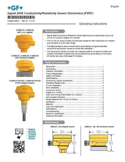
3-2850-61, 3-2850-62, 3-2850-63with Universal adapter3-2850-51, 3-2850-52with ¾-in. adapter3-2850-51-XXV(D), 3-2850-52-XXV(D)PVDF Integral SystemSignet 2850 Conductivity/Resistivity Sensor Electronics (PVDF)3-2850.090-2 Rev. B 01/15*3-2850.090-1*EnglishOperating Instructions• English • Deutsch • Français • Español •Italianofi eld calibration.2850-61, -62, -63 Universal mount11222 2334455 (567888991012)22850 Conductivity/Resistivity Sensor Electronics32850 Conductivity/Resistivity Sensor Electronics42850 Conductivity/Resistivity Sensor Electronics52850 Conductivity/Resistivity Sensor Electronics62850 Conductivity/Resistivity Sensor ElectronicsNOTE:To work correctly with the 9900, the 2850 must be set for thecustom cell constant or the actual electrode cell constant and the 9900 set for a 1.0 cell constant.123SW1SW3D3Input 1123SW1SW3SW4D3Input 1Input 21234123412341234123412340.01/cm -10.1/cm -11.0/cm -110.0/cm -120.0/cm -1Closed OpenClosedOpenClosedOpenClosedOpenClosed OpenClosed OpenCustom Cell Constant12341234OpenClosedOpenClosed1.0 cell constant, temp comp Active1.0 cell constant,temp comp InactiveExamples NOTE: D ual Input applications usually include one sensor with a smaller cell constant and onesensor with a larger cell constant. Place the larger cell constant on Input 1.This allows periodic recalibration of the larger cell by simply turning Input 2 OFF (OPEN).SW3 = C ell Constant andTemperature Compensation#1 #2 #3 #4 Cell Constant C C C O Custom C O O O 0.01 cm -1 O C O O 0.1 cm -1 C C O O 1.0 cm -1 O O C O 10.0 cm -1 C O C O 20.0 cm -1#4: (O) Open = Temp Comp ACTIVE (C) Closed = Temp Comp INACTIVESW4 = C ell Constant and Input 2#1 #2 #3 #4 Cell ConstantC C C O Custom C O O O 0.01 cm -1 O C O O 0.1 cm -1 C C O O 1.0 cm -1 O O C O 10.0 cm -1 C O C O 20.0 cm -1#4: (O) Open = Input 2 INACTIVE (C) Closed = Input 2 ACTIVESW3 or SW4Integral 2850 Systems (Single Input)• The 2850-51-XX and 2850-52-XX are shipped from the factory with the custom cell constant and temperature offset programmed into the single-input electronics.• SW3 will be preset to "Custom cell constant".• No additional modi fi cations are required.Replacing Integral System Electrode or Electronics• When installing a new conductivity electrode or replacing System Electronics, the SW3 switches must be con fi gured to select the appropriate cell constant. • See Single Input section above.• Leaving SW3 in the custom cell constant con fi guration will effect accuracy.• Use calibration standards to calibrate (see page 8).Dual Input 3-2850-63 Electronics• Switch banks SW3 and SW4 are used to select the cell constant of the electrodes.• Use SW3 #1-3 to select the cell constant for the fi rst sensor.• Use SW3 #4 to disable the PT1000 TempCompensation function in the 2850 (as required for USP applications).This disables the function for BOTH INPUTS.• Use SW4 #1-3 to select the cell constant for the second sensor.• Set SW4 #4 to OPEN to disable Input 2.• Recommended:Make all switch settings before supplying power. Switch changes made after supplying power will take 15 to 20 seconds before becoming effective.Single Input 2850 Electronics(2850-51, 2850-52, 2850-61, 2850-62)• Single input models use only SW3.• Use SW3 #1-3 to select the cell constant for the fi rst sensor.• Use SW3 #4 to disable the PT1000 TempCompensation function in the 2850 (as required for USP applications).• Recommended:Make all switch settings before supplying power. Switch changes made after supplying power will take 15 to 20 seconds before becoming effective.72850 Conductivity/Resistivity Sensor Electronics82850 Conductivity/Resistivity Sensor Electronics92850 Conductivity/Resistivity Sensor Electronics102850 Conductivity/Resistivity Sensor Electronics112850 Conductivity/Resistivity Sensor ElectronicsOrdering InformationSignet 2850 Conductivity/Resistivity Sensor Electronics*All versions include EasyCal Mfr. Part No.Code Description3-2850-51159 001 3982850 Sensor Electronics with Digital (S3L) Output and ¾ inch adapter3-2850-52159 001 3992850 Sensor Electronics with 4 to 20 mA Output and ¾ inch adapter3-2850-61159 001 4002850 Sensor Electronics with Digital (S3L) Output and Universal adapter3-2850-62159 001 4012850 Sensor Electronics with 4 to 20 mA Output and Universal adapter3-2850-63159 001 4022850 Sensor Electronics with Dual Inputs, Dual Digital (S3L) Outputs and Universal adapter(for use with 8900 only)3-2850-51-39V159 001 818Integral 2850 system, Digital (S3L) output, 0.01 cell, PVDF NPT threads3-2850-51-40V159 001 819Integral 2850 system, Digital (S3L) output, 0.1 cell, PVDF NPT threads3-2850-51-41V159 001 820Integral 2850 system, Digital (S3L) output, 1.0 cell, PVDF NPT threads3-2850-51-42V159 001 821Integral 2850 system, Digital (S3L) output, 10.0 cell, PVDF NPT threads3-2850-51-39VD159 001 822Integral 2850 system, Digital (S3L) output, 0.01 cell, PVDF ISO threads3-2850-51-40VD159 001 823Integral 2850 system, Digital (S3L) output, 0.1 cell, PVDF ISO threads3-2850-51-41VD159 001 824Integral 2850 system, Digital (S3L) output, 1.0 cell, PVDF ISO threads3-2850-51-42VD159 001 825Integral 2850 system, Digital (S3L) output, 10.0 cell, PVDF ISO threads3-2850-52-39V159 001 826Integral 2850 system, 4 to 20 mA output, 0.01 cell, PVDF NPT threads3-2850-52-40V159 001 827Integral 2850 system, 4 to 20 mA output, 0.1 cell, PVDF NPT threads3-2850-52-41V159 001 828Integral 2850 system, 4 to 20 mA output, 1.0 cell, PVDF NPT threads3-2850-52-42V159 001 829Integral 2850 system, 4 to 20 mA output, 10.0 cell, PVDF NPT threads3-2850-52-39VD159 001 830Integral 2850 system, 4 to 20 mA output, 0.01 cell, PVDF ISO threads3-2850-52-40VD159 001 831Integral 2850 system, 4 to 20 mA output, 0.1 cell, PVDF ISO threads3-2850-52-41VD159 001 832Integral 2850 system, 4 to 20 mA output, 1.0 cell, PVDF ISO threads3-2850-52-42VD159 001 833Integral 2850 system, 4 to 20 mA output, 10.0 cell, PVDF ISO threadsParts and Accessories3-9000.392-1159 000 839Liquid-tight connector kit, 1 set, 1/2 in. NPT3-9000.392-2159 000 841Liquid-tight connector kit, 1 set, PG 13.53-2850.101-1159 001 392Plug-in NIST-traceable recertifi cation tool, 1.0 μS3-2850.101-2159 001 393Plug-in NIST-traceable recertifi cation tool, 2.5 μS3-2850.101-3159 001 394Plug-in NIST-traceable recertifi cation tool, 10.0 μS3-2850.101-4159 001 395Plug-in NIST-traceable recertifi cation tool, 18.2 MΩ3-2850.101-5159 001 396Plug-in NIST-traceable recertifi cation tool, 10.0 MΩGeorg Fischer Signet LLC, 3401 Aero Jet Avenue, El Monte, CA 91731-2882 U.S.A. • Tel. (626) 571-2770 • Fax (626) 573-2057For Worldwide Sales and Service, visit our website: • Or call (in the U.S.): (800) 854-4090For the most up-to-date information, please refer to our website at 3-2850.090-2 Rev. B 01/15 English © Georg Fischer Signet LLC 2015。
温度传感器使用说明
Executi ng division : Responsible division : Document type : Confidentiality status :HCN NVPTechnical Documentation InternalPrepared :Document state :08.02.2006 Czernietzki (NVP)Technology Transfer HCN PreliminaryChecked :09.02.2006 Czernietzki (NVP)FNC System BusinessThermistorsApproved :File:Revision :Language :Pages :09.02.2006 Czernietzki (NVP) TD-Thermistors-en-R001 001 en 1/19This document and its contents are the property of Hoppecke or its subsidiaries. This document contains confidential proprietary information. The reproduction,Document administration 文件管理Document History 文件记录VersionDateResponsibleReason of change001 08.02.2006 Czernietzki First release of the document.Change justifiable 变更审核Hans-Peter Czernietzki NVPPreparing , Checking , ApprovingLewis Liu HCN QS Preparing , Checking , ApprovingDocument generated with following tools 使用下列工具编写文件:WORD 200 <Grafic tool>Content 目录1 Overview Thermistors........................................................................................................................................................................2 1.1 General.....................................................................................................................................................................................2 1.2 NTC Thermistors.....................................................................................................................................................................4 1.3 PTC Thermistors......................................................................................................................................................................5 1.4 Lead wire configurations..........................................................................................................................................................6 1.5 Available temperature probe....................................................................................................................................................8 1.6 Available connection cables.....................................................................................................................................................8 2 Designs...............................................................................................................................................................................................9 2.1 Stainless steel block version.....................................................................................................................................................9 2.2 Electrolyte version...................................................................................................................................................................9 2.3 Connection cables..................................................................................................................................................................10 2.3.1 Two wire connection 414 220 0802.............................................................................................................................10 2.3.2 Four wire connection 414 220 0804............................................................................................................................10 2.3.3 Connection clamp........................................................................................................................................................10 2.4 Temperature curve PT100B...................................................................................................................................................11 2.5 Temperature curve NTC10K..................................................................................................................................................11 2.6 Technical data NTC10K.........................................................................................................................................................11 3 Attachments......................................................................................................................................................................................11 3.1 Drawing 2BZ60287-01..........................................................................................................................................................11 3.2 Drawing 3BZ60731-01..........................................................................................................................................................11 3.3 Drawing 2BZ60287-02..........................................................................................................................................................11 3.4 Drawing 3BZ60407-01..........................................................................................................................................................11 3.5 Drawing 3BZ60732-01..........................................................................................................................................................11 3.6 Drawing 3BZ60407-02. (11)1 Overview Thermistors电热调节器简介1.1 General总则Resistance elements come in many types conforming to different standards, capable of different temperature ranges, with various sizes and accuracies available. But they all function in the same manner: each has a pre-specified resistance value at a known temperature which changes in a predictable fashion. In this way, by measuring the resistance of the element, the temperature of the element can be determined from tables, calculations or instrumentation. These resistance elements are the heart of the RTD (Resistance Temperature Detector or short: Thermistor). Generally, a bare resistance element is too fragile and sensitive to be used in its raw form, so it must be protected by incorporating it into an housing.电阻元器件满足不同的标准,能够适用不同的温度范围,可满足多种尺寸和精度要求。
+GF+ SIGNET 515和3-8510 X型转轮流量传感器操作说明书

技术支持:0755-89800917
+GF+ SIGNET 515 和 3-8510 X 型转轮流量传感器操作说明书
安全说明:
1
1 禁止从带压管道上拆卸;
2 禁止使用工况超过最大压力和温度;
3 管道安装件必须由合格焊工安装;
4 没有以下安装说明书,禁止安装和操作;
3 传感器的接线
• 使用 2 芯屏蔽电缆 l 连接可将长度 延长至 60m(200 英尺)
• 连接时电缆屏蔽层一定要接好 • 特殊的接线细节可参考仪表手册
4 +GF+ SIGNET 安装件
型式 描述
塑料’T’形
PVC 粘接鞍 形(无 需O型 圈) 铸铁捆 式鞍形
· 0.5-4in. · PVC 或 CPVC · 用粘接安装件安装 · 2-4in.,开 Φ1-7/16 的孔 · 4-8in.,开 Φ 2-1/4 的孔 · 组装时楔形与鞍形上的箭头在一条直线 上
介质情况:
515/3-8510-XX 传感器压力和温度比率: PP 本体: · 最大 12.5bar(180psi) @20℃(68ºF) · 最大 1.7bar(25psi) @90℃(194ºF) PVDF 本体: · 最大 14bar(200psi) @20℃(68ºF) · 最大 1.7bar(25psi) @100℃(212ºF) 319’Wet-tap’组件压力和温度比率 · 最大 7bar(100psi)@25℃(77ºF) · 最大 1.4bar(20psi)@66℃(150ºF)
7 ‘Wet-Tap’型安装
+GF+ SIGNET 319’Wet-Tap’组件可以直接安 装在+GF+ SIGNET 安装件上从而使其可以从运行 管道上取下传感器。该组件包括 1 个法兰,固定在安装 件上的支撑盘,1 个 PVC 球阀。加长的 515 传感器通 过球阀插入管道。
- 1、下载文档前请自行甄别文档内容的完整性,平台不提供额外的编辑、内容补充、找答案等附加服务。
- 2、"仅部分预览"的文档,不可在线预览部分如存在完整性等问题,可反馈申请退款(可完整预览的文档不适用该条件!)。
- 3、如文档侵犯您的权益,请联系客服反馈,我们会尽快为您处理(人工客服工作时间:9:00-18:30)。
‡ SIGNET 2820 Series Conductivity Sensor Instruction ManualENGLISH1. Wiring2. Recommended Position3. 2819/2820/2821 In-line InstallationSAFETY INSTRUCTIONS FOR IN-LINE ELECTRODE INSTALLATION 1.Do not remove from pressurized lines.2.Do not exceed maximum temperature/pressure specifications.3.Wear safety goggles or face shield during installation/service.4.Do not alter product construction.Failure to follow safety instructions may result in severe personal injury!Customer supplied pipe tee/reducerStandardfitting kit Hole up Mark holeposition3/4 in. NPTHand tighten only!Optional fitting kit Hole up Mark hole positionCustomer supplied pipe tee/reducer1/2 in. NPTHand tighten only!O-ringO-ringSealantSealant+GF + SIGNET 5800CR•Use three conductor shielded cable for cable extensions up to 30 m (100 ft max.• Shield must be maintained through cable spliceREDWHITE BLACK SILVER (SHLDS h l dS i g n a l I NT e m p . I NI s o . G n dCH 2CH 1RED SILVER (SHLDBLACKSILVER (SHLDBLACKCNOTx GND RxCH2S2 T2S1 T1 SGCNOR+R-RLY3RLY4SERIAL ANL2CH11 2 3 4 5 6 7 8 9 10 11 12 13 14WHITE RED WHITE+GF + SIGNET 9050CRIn-line 2821-1Use caution to avoid air bubble or sediment trapping inside the electrode cavity. SubmersibleOR(J-2/03 English3-2820.090-14. 2822 In-line Installation5. 2823 In-Line InstallationCustomer supplied pipe tee/reducer Sealant1-1/4 turns past finger tightHole upMark hole positionInstall behind hole ONLY!Customer supplied pipe tee/reducer3/4 in. NPTSealant121-1/4 turns past finger tight3/4 in. NPT Customer supplied coupling Customer supplied pipe SealantSealant6. 2819/2820/2821 Submersible Installation7. 2822 Submersible Installation2Standard fitting kitOptional fitting kit3/4 in. NPT1/2 in. NPT1Customer supplied pipe Customer supplied couplingHand tighten only!Standard fitting kitOptional fitting kitO-ring SealantSealantOptional submersion fitting kit #3-2820.390121-1/4 turns past finger tight3/4 in. NPT Customer supplied pipe Customer supplied coupling SealantSealant8. 2823 Submersible InstallationFill with 3 to 4 in. of sealantAttach 3/4 in. watertight pipe to the top of the sensor. Secure the threaded connection to prevent any leakage. For additional defense against possible accumulation of condensation at the back seal area of the sensor, fill the lower 3-4 inches (75-100 mm of conduit or extension pipe with a flexible sealant such as silicone.2819-1/2820-1/2821-1•2819-1 cell:0.012819-1 range:0.010 to 100 µS (10 kΩ to 100 MΩ•2820-1 cell:0.12820-1 range: 1 to 1000 µS•2821-1 cell: 1.02821-1 range:10 to 10,000 µS Temperature compensation:PT1000Wetted materials:•O-rings:EPR•Insulator material:PTFE•Electrodes:316 stainless steelStandard fitting:Polypropylene•Max. pressure: 6.9 b ar (100 psi•Max. temperature:100 °C (212 °FOptional fitting:316 stainless steel (1/2 in. NPT•Max. pressure:13.8 bar (200 psi•Max. temperature:120 °C (248 °FQuality Standard:CE 6 in./152 mm4.2 in./107 mm2 in./50 mm0.8 in./21 mm3/4 in. NPT15 ft/4.6 m cable (std. Reversiblefitting assy.for submersion mounting0.5 in./13 mm2821-1sensor tip2820-1sensor tip0.3 in./8 mm2819-S1/2820-S1/2821-S1/2819-T1/2820-T1/2821-T1•2819-X1 cell:0.012819-X1 range:0.010 to 100 µS (10 kΩ to 100 MΩ•2820-X1 cell:0.12820-X1 range: 1 to 1000 µS•2821-X1 cell: 1.02821-X1 range:10 to 10,000 µSSanitary fitting size: 1 and 11/2 in.Temperature compensation:PT1000Wetted materials:•O-rings:EPR•Insulator material:PTFE•Electrodes:316 stainless steel or titanium Sanitary fitting:316 stainless steel or titaniumMax. pressure: 6.9 bar (100 psiMax. temperature:120 °C (248 °FQuality Standard:CE2819-S2/2820-S2/2821-S2/2819-T2/2820-T2/2821-T2•2819-X2 cell:0.012819-X2 range:0.010 to 100 µS (10 kΩ to 100 MΩ•2820-X2 cell:0.12820-X2 range: 1 to 1000 µS•2821-X2 cell: 1.02821-X2 range:10 to 10,000 µSSanitary fitting size: 2 in.Temperature compensation:PT1000Wetted materials:•O-rings:EPR•Insulator material:PTFE•Electrodes:316 stainless steel or titanium Sanitary fi tting:316 stainless steel or titaniumMax. pressure: 6.9 bar (100 psiMax. temperature:120 °C (248 °FQuality Standard:CE152 mm6.0 in./13 mm0.5 in./50 mm2.0 in./126 mm5.0 in./2820-X1sensor tip2821-X1sensor tip50 mm2.0 in./21 mm0.8 in./8 mm0.3 in./ 15 ft/4.6 m cable (std.64 mm2.5 in./152 mm6.0 in./13 mm0.5 in./126 mm5.0 in./2820-X2sensor tip2821-X2sensor tip50 mm2.0 in./21 mm0.8 in./8 mm0.3 in./ 15 ft/4.6 m cable (std.9. SpecificationsAlternate wetted materials and overall lengths are available through special order. Cable length extensions to 100 ft. (30 m are available through special order. For resistivity measurements above 10 MΩ and/or below 20°C, maximum cable length is 25 ft. (7.6 m.ASensor tip (side viewElectrodeBInsulatorCElectrodeCotton swab• Clean electrode • Clean metal body8-32Sensor tip (end viewDInsulatorSensor tip (side view10. MaintenanceAny coatings on electrodes will cause readings to drift or show poor response. Clean metallic surfaces with a mild detergent and a non-abrasive brush or cotton swab.2823-1 Sensor Tip Removal Procedure:11. AccessoriesPart No.Description3-2820.392Optional 1/2" 316 SS Fitting 3-2820.390Optional 3/4" 316 SS Fitting‡ SIGNETSignet Scientific Company, 3401 Aerojet Avenue, El Monte, CA 91731-2882 U.S.A. • Tel. (626 571-2770 • Fax (626 573-2057For Worldwide Sales and Service, visit our website: • Or call (in the U.S.: (800 854-4090GEORGE FISCHER ‡ Piping Systems 3-2820.090-1(J-2/03 English © Scientific Company 2003Printed in U.S.A. on recycledpaper2822-1Cell:10.0Range:100 to 200,000 µS Temperature compensation:PT1000Wetted materials:•O-rings:EPR •Insulator material:CPVC•Electrodes:316 stainless steel Standard fitting:316 stainless stee l Max. pressure: 6.9 bar (100 psiMax. temperature:95 °C (203 °FQuality Standard:CE2823-1Cell:20.0Range:200 to 400,000 µS Temperature compensation:PT1000Wetted materials:•O-rings:EPR •Insulator material:PTFE•Electrodes:316 stainless steel Fitting:316 stainless steel Max. pressure: 6.9 bar (100 psiMax. temperature:150 °C (302 °FQuality Standard:CE8.0 in./203 mm15 ft./4.6 m cable (standard3/4 in. NPTReversible fitting assy for submersion mounting 3.5 in./89 mm0.75 in.19 mm5.8 in./147 mm3.4 in./86 mm15 ft/4.6 m cable (std.Optional 316 SS submersion fitting kit #3-2820.3903/4 in. NPT19 mm0.75 in.3/4 in. NPT。