ETS1701-100-Y00说明书
液晶杜邦17011电源电源测试系统说明书

EthernetMODEL 17011KEY FEATURESHigh precision output and measurement up to 0.015% of full scaleFast current response up to <100 µS High sampling rate up to 10 mS Flexible sampling recording ( t, V , I, Q, E)Channel parallel output function with maximum 1200A outputHigh efficiency charge and discharge with low heatingEnergy recycling during discharge (AC/DC bi-directional regenerative series) Waveform simulation function (current/power mode) Built-in DCIR test functionBuilt-in EDLC capacitance and DCR test functionOperating modes: CC / CP / CV / CR / CC-CV / CP-CV / Rest / SD test Multi-level safety protection mechanism Integrable data logger and chamberAPPLICATIONSElectric vehicle Electric scooter/bike Energy storage system Power toolsQuality inspection agency The Chroma 17011 Battery Cell Charge and D ischarge Test System is a high precision system designed specifically for testing lithium-ion battery (LIB) cells, electrical double layer capacitors (ED LC), and lithium-ion capacitors (LIC). It is suitable for product development, quality control, and is helpful program editing and test results analysis much easier.The Chroma 17011 test system has flexible software editing functions embedded that can create basic charging/discharging or complex cycle tests for each channel to run BATTERY CELL CHARGE & DISCHARGETEST SYSTEM MODEL 17011P r o vided b vided by y : com (800)40404-A -ATE TEC CAd Advanced vanced T Test estE quipment Rentals®High precision – improving product qualityVoltage / current measurement accuracy: 0.015 of F.S. / 0.02 of F.S.Wide range of voltage output: Equipped with a 0V to 6V output range, and specific models allow to switch between three built-in voltage output modes. Voltage measurements distinguished up to 0.1mV.Multiple range measurement design: Providing various current or voltage ranges (depending on the model) to greatly improve measurement accuracy and resolution. The current range switches automatically and at the constant voltage mode there is no current output interruption.Fast current response – suitable for a variety of high-speed transient test applicationsCurrent response time (10% to 90%) < 100 µS *1Support dynamic waveform to simulate the rapid changing current and power states*1: The current response time <100 µS applies to model 17216M-10-6, the impedance of other UUTswill slightly differ.Rise Time<100 µS (17216M-10-6)Rise Time<250 µS (17208M-6-30)Model 17216M-10-6Model 17216M-6-12Model 17208M-6-30Model 17208M-6-60Multi-Voltage Range (17216M-10-6)Multi-Current RangeLoading waveform currentDynamic waveform simulation Dynamic waveform simulationCurrent and power dynamic charge/discharge waveform, simulate the actual battery usage of car driving or other real life applicationsImport the current and power waveforms from Excel fileSave 1,440,000 points in each channel for long hour dynamic testingMinimalize time interval for data output: 10 mS*1: 17216M-10-6 has three built-in voltage output modes that can be switched through the software settings.*2: 17208M-6-60 has to be paired with an external power supply and placed into a rack; other models contain an integrated power module and can beused either stand-alone or in a rack.Rise time < 5 mSEnergy recycling – optimal utilization of electricityDirect recycling: Automatically transfer the discharging energy to the battery cells to be charged with recycling efficiency >80% Grid recycling: Recycle the excessiveenergy to the grid with recyclingefficiency >60%Low carbon emissions for green energy,preventing waste heat from generatingduring dischargeSaving electricity costs with highefficiency power charge and dischargeSaving air conditioning costs on coolingequipmentCurrent harmonic distortion <5%for feedback to grid currentPower factor >0.98 at rated powerHigh precision – improving product qualityVoltage accuracy: (0.02% of Reading + 0.02% of F.S.)Current accuracy: 0.05% of F.S.Fast current response – waveform modeCurrent response speed (10% to 90%) < 5 mS applicablefor all kinds of testsSupport dynamic waveform to simulate the current and power stateof actual car driving with NEDC, FUDS and DST test standardsAC/DCChroma 17212M-6-100Chroma A691104Direct RegenerationAC/DC* A fitting AC/DC bi-directional converter is chosen according to the power input and placed into a rack.Flexible paralleling channels for outputT h e t e s t s y s t e m s a l l o w f l e x i b l e s e t t i n g f o for various UUTs.which supports full range of productsSuitable for high ratio charge and discharge test or diversified battery test applicationsData protection and recoveryPower loss data restoring mechanism: After a power loss, the PC will automatically recover the data status of the testingdata that already was written into the database. The user can choose to resume or restart testing.High frequency sampling measurement technology – improving measurement accuracyV / I sampling rate: 50 KHz (∆t 20 µS)Generally, battery testers use software to read current values for calculating power; however, limited data sampling rates could result in large errors when calculating the dynamic current capacity. By increasing the sampling rate and using a double integration method, Chroma 17011 is able to provide a capacity calculation with much higher accuracy. When the current changes, the data is not lost and the transmission speed is not affected.* Note: The current response time <100 µS applies to model 17216M-10-6, the impedance of other UUTs will slightly differ.General charger/discharger sampling rateChroma charge & discharge tester sampling rateHPPC TestHPPC test applicationHPPC is a test procedure developed by the USABC (U.S. Advanced Battery Consortium) for the battery power performance of hybrid and electric vehicles. Within the batteries operation voltage range, the procedure mainly establishes the function of the relationship between the depth of discharge and power and, secondarily, establishes the depth of discharge, conductive resistance and polarization resistance function via the voltage and current response curve from discharging, standing to charging. The measured resistance can be used to assess the battery's power recession during later life tests and its equivalent circuit model development. Chroma 17011 has a flexible editing program that allows HPPC testing.DCIR test (2)DCIR test (1)Lumped parameter model circuit diagram Battery capacity test applicationT h e c a p a c i t y c a n b e o b t a i n e d a s t h e i n t e g r a l o f t h e c u r re n t integrating the current versus time from the start of charging/discharging until the cut-off condition is reached. The comparison results are useful to analyze performance differences between products, and the common test items include current ratio and temperature characteristics tests. Higher accuracy of current, voltage measurement and faster sampling enable to distinguish more accurately the differences in battery cell capacity.Battery cycle life test applicationCycle life is one of the most important test items for batteries. In accordance with the experimental purpose, it tests the same battery through repeated charge and discharge conditions until the capacity falls to 80%, and calculates the cycle numbers. The cycle life test can be used to evaluate the battery performance or define the applicable conditions of use.Battery DCIR test applicationThe internal resistance value is related to the charge/discharge ratio of a battery. The larger the internal resistance value, the lower the efficiency when temperature rises. According to the lithium-ion battery equivalent circuit model, the ACIR measurement of traditional 1KHz LCR meters can only evaluate the conductive resistance (Ro) of the battery that affects the instantaneous power output, but is unable to evaluate the polarization resistance (Rp) produced during electrochemical reaction. The D CIR evaluation includes the ACIR that is closer to the actual polarization effect of battery under continuous power applications.The Chroma 17011 includes two types of D CIR test modes: DCIR test (1) calculates the DCIR value using the voltage difference caused by the change of one-step current, DCIR test (2) calculates the DCIR value using the voltage difference caused by the change of two-step current. Users can select the desired test mode and automatically, without any manual calculation, get the results that comply with IEC 61960 standards.CapacitydQ/dV vs voltageCoulombic efficiency test Incremental capacity analysis applicationThe high precision voltage measurement and V sampling function can draw dQ/dV versus voltage curve diagrams to analyze battery cell characteristics and capacity degradation.Coulombic efficiency test applicationCoulombic efficiency (CE) is calculated by the charge/discharge capacity ratio when the battery is fully charged and then fully discharged. Good batteries have higher coulombic efficiency, and need high precision and stable equipment to distinguish differences. An accurate coulombic efficiency test can estimate the batterylifespan with only a few cycles.EDLC capacitance (C) test applicationIn accordance with the Straight Line Approximation Method of the IEC 62391 testing standard, before measuring the capacitance (C) value, the ED LC first needs to be fully charged through a CC-CV charging mode. The capacity test is to discharge CC via the above discharge current. Then, the electric potential difference ( V) of two reference points on the discharge curve are taken against the time difference ( t) and the discharge current (I) to calculate the capacitance value of the EDLC.EDLC combined DCR and C test applicationChroma 17011 also has a direct current resistance (D CR) and capacitance (C) combined test application. Under the same CC-CV charged and CC discharged conditions, the user can use the electric potential in the chosen reference points to simultaneously calculate the DCR and C values of the EDLC to save testing time.The equivalent circuit model development of the classical EDLC includes an equivalent series resistance (ESR), a capacitance (C), and an equivalent parallel resistance (EPR). The ESR is used to evaluate the internal loss and heat of the EDLC during charging/discharging; the EPR to evaluate the leakage effect in the EDLC's long-term storage; the C to evaluate the EDLC cycle life.These parameters are not easily directly measured in a laboratory; researchers need data analysis and complex calculations to determine these important indicators. Chroma 17011 is equipped with the IEC 62391 testing standards and the user can use charge/discharge tests to obtain the ED LC parameters values, in order to evaluate the EDLC characteristics and cycle life.ED LC direct current resistance (D CR) and equivalent series resistance (ESR) test applicationChroma 17011 offers ED LC direct current resistance testing function compliant with test standard IEC 62391. Before testing, the ED LC has to be CV charged. The capacity test is to discharge CC via the above discharge current. When the discharge is completed, get the linear section on the discharge curve and extend it to discharge time and then get the voltage difference of rated voltage and discharge current to calculate the DCR value.EDLC equivalent circuit model developmentVoltage Characteristic Between EDLC TerminalsVoltage Characteristic Between EDLC TerminalsVoltage Characteristic Between EDLC TerminalsCharge/discharge performance and cycle life test applicationThe built-in direct current resistance (D CR) and capacitance (C) test modes can be combined with cycle function and variable set testing conditions to test the EDLC load endurance and reliability. After testing, the user can directly export DCR vs Cycle No. and Capacity vs Cycle No. reports to analyze the EDLC failure and deterioration mechanisms.Self-discharge test modeCoulombic efficiency testAutomatically change current range in CC-CV modeCharge-Discharge Rate Test Charge-Discharge Cycle TestingCoulombic efficiency test applicationChroma 17011 is equipped with low noise, automatically switching current range, and cut-off report as to quickly output accurate c u r re n t c h a rg e /d i s c h a rg e. T h e c o u l o m b i c e ff i c i e n c y (C E ) i s calculated by the charge/discharge capacity ratio, which indicates the ED LC internal capacity conversion as available capacity. A highly accurate CE is an important marker to distinguish differences between products.Leakage current test applicationED LC leakage current measurements generally need to CC-CV charging until a specific time and then it measures this tiny charging current, which is seen as leakage current. The Chroma 17011 CC-CV mode can automatically change current range without output interruption. Under stable voltage, the current range can be as small as 200µA.Current (A)Self-discharge test applicationChroma 17011 also has a built-in self-discharge test mode, when the ED LC is fully charged it can test the charge/discharge for a set time period. When this mode starts, the system will cut off the measuring circuit to provide the ideal open circuit and solely measure the starting potential (V1) and cut-off potential (V2). The software can automatically calculate the electric potential difference ( V).CE=Q Discharge / Q ChargeThe Chroma 17011 test systems are controlled by computer software with diverse functions for testing energy storage products. The safe, stable and friendly operation interface allows users to perform setting and testing rapidly.Support English, Traditional Chinese, and Simplified Chinese languages interfaces Real time multi-channel DUT status monitoringSecurity management: set user authority for safe managementFailure record tracking: independently record abnormalities for each channel, the charge and discharge protection will abort the testwhen an abnormal condition is detectedRecipe editing500 steps per recipeDouble loop (Cycle & Loop) with 999,999 repeat counts per loop Sub-recipe function: Call existing recipesTest steps : CC / CV / CP / CC-CV / CP-CV / CR / Rest / Waveform / DCIR / C / DCR, etc. Cut-off conditions : Time / Current / Capacity / Power / Variable, etc. Logical operations : Next / End / Jump / If-Then Recipe executingOperating modes: Start / Stop / Pause / Resume / Jump / Reserve Pause / Modify during test Display interfaces: Graphic display / Table display Instant monitoring windowStatistics reportAble to define report formats and export them as PDF, CSV, and XLS filesGraphical report analysis functions allow custom reports such as cycle life reports, Q-V reports, V / I / T time reports, etc.Real time monitoring Charge/Discharge test program editor Test diagram Test reportBattery Pro main panelWaveform current editorIntegrate with an environmental chamber through software to synchronize the settings conditions for charge/discharge testingIntegrate with a multifunctional data logger through software to read and set multiple temperature records during thecharge/discharge process. Change these conditions to protection or cut-off conditions17011 SystemData LoggerLinear circuit modelsThe tester can be used stand-alone to take up little space, which fits a handful of tests performed on the desktop. When the tester is configured with more test channels, it can be integrated into a standard 19-inch rack for use. The system can be configured as demanded by the user as the channel numbers are expandable, and up to 64 channels can be controlled by one PC at the same time.60A 36U rackModel 17208M-6-306A/12A/30A 36U rackModel 17216M-10-625U rackRegenerative modelsA charge/discharge tester and an AC/D C bi-direction converter can be integrated into a standard 19-inch rack for use. The system can be configured as demanded by the user as the channel numbers are expandable, and up to 48 channels can be controlled by one PC at the same time.Chroma 17011 system power consumption * Available space for data logger60A / 41U system100A / 41U systemORDERING INFORMATION17011 : Battery Cell Charge & Discharge Test System17216M-10-6 : Programmable Charge/Discharge Tester, 10V / 6A, 16CH 17216M-6-12 : Programmable Charge/Discharge Tester, 6V / 12A, 16CH 17208M-6-30 : Programmable Charge/Discharge Tester, 6V / 30A, 8CH 17208M-6-60 : Programmable Charge/Discharge Tester, 6V / 60A, 8CH 17212R-5-60 : Programmable Charge/Discharge Tester, 5V / 60A, 12CH 17212R-5-100 : Programmable Charge/Discharge Tester, 5V / 100A, 12CH 17212M-6-100 : Programmable Charge/Discharge Tester, 6V / 100A, 12CH A691103 : DC/AC Bi-direction Converter, AC 220V to DC 45V A691104 : DC/AC Bi-direction Converter, AC 380V to DC 45V* All specifications are subject to change without notice.* Continued on next pageNote*1: The maximum discharge current will derate at low voltage 17011-E-201908-PDFJAPANCHROMA JAPAN CORP .888 Nippa-cho, Kouhoku-ku,Yokohama-shi,Kanagawa,223-0057 Japan T +81-45-542-1118F +81-45-542-1080www.chroma.co.jp**************.jp U.S.A.CHROMA ATE INC.(U.S.A.)7 Chrysler, Irvine,CA 92618T +1-949-421-0355F + *****************CHROMA SYSTEMS SOLUTIONS, INC.19772 Pauling, Foothill Ranch, CA 92610 T +1-949-600-6400F + *******************EUROPECHROMA ATE EUROPE B.V .Morsestraat 32, 6716 AH Ede,The Netherlands T +31-318-648282F + ******************CHROMA GERMANY GMBH Südtiroler Str. 9, 86165,Augsburg, Germany T +49-821-790967-0F + ******************CHINA CHROMA ELECTRONICS (SHENZHEN) CO., LTD.8F , No.4, Nanyou Tian An Industrial Estate,Shenzhen, China T +86-755-2664-4598F +86-755-2641-9620 ******************SOUTHEAST ASIA QUANTEL PTE LTD.(A company of Chroma Group)46 Lorong 17 Geylang # 05-02 Enterprise Industrial Building,Singapore 388568T +65-6745-3200F + ************************HEADQUARTERS CHROMA ATE INC.66 Huaya 1st Road,Guishan, Taoyuan 33383, TaiwanT +886-3-327-9999F + ******************KOREA CHROMA ATE KOREA BRANCH 3F Richtogether Center, 14,Pangyoyeok-ro 192,Bundang-gu,Seongnam-si,Gyeonggi-do13524, Korea T +82-31-781-1025F +82-31-8017-6614www.chromaate.co.kr ******************17011。
ES100使用说明
北京华控自动化系统有限责任公司目录ES100简介 (1)ES100简介 (1)ES100主要性能指标 (1)安装方式 (2)ES100俯视图及端口定义和接线说明 (3)俯视图 (3)端子定义 (3)接线说明 (4)流量传感器、变送器 (4)压力变送器 (5)温度传感器、变送器 (5)画面显示 (6)用户操作 (7)附录1:常用公式 (13)附录2:上位机组态模板 (14)CAN通信方式组态模板 (14)485/以太网通信方式组态模板 (16)ES100简介ES100简介ES100能源计量控制器采用16位高精度A/D转换器,先进的微处理器及浮点数运算方式,有效的保证了整机的信号测量精度和流量计量精度。
产品为128×64图形点阵液晶显示器,通过简单的设置可以实现对饱和蒸汽、过热蒸汽、液体和混合气体流量等参量的计量,并可以实现压力补偿密度,温度补偿密度,温度、压力补偿密度等。
ES100能源计量控制器具有多种网络通信方式,仪表地址及通信波特率可通过窗口参数调整。
同一条总线上可挂接多个仪表。
ES100能源计量控制器可直接与多种流量计配套,操作简易,功能齐全,可靠性高。
ES100主要性能指标1、流量输入信号:传感器:差压、涡街、电磁、涡轮信号类型:0~10mA、4~20mA、脉冲(1~5,000Hz)2、压力输入信号(补偿信号):传感器:压力变送器信号类型:0~10mA、4~20mA3、温度输入信号(补偿信号):传感器:温度变送器、铂电阻(三线制)信号类型:0~10mA、4~20mA、Pt100等4、流量再发送模拟量输出信号信号类型: 4~20mA(最大负载:≤500Ω)数据更新周期:≤0.5s5、基本误差:频率信号输入:读数的0.1%温度信号输入:±0.5℃(-200~560℃)电压电流输入:满量程的±0.1%补偿后流量显示:满量程的±0.2%6、通信功能(需根据用户订货要求配备):具有CAN、RS485、以太网通信接口。
太阳能热水器控制仪使用说明书资料
太阳能热水器控制仪使用说明书太阳能热水器使用说明,一般情况下也就是说的太阳能热水器控制仪的使用方法,在这里我们拿最常用的西子控制仪说明书,为大家讲解一下使用方法,希望对大家在使用过程中减少一些疑难问题,方便大家使用。
TMC至尊全天候测控仪使用说明书【主要技术指标】1.使用电源:220VAC功耗:<5W2.测温精度:±2℃3.测温范围:0-99℃4.控温精度:±2℃5.水位分档:五档环形显示6.可控水泵或电热带功率:≤500W7.可控电加热功率:≤1500W可选:3000W8.漏电动作电流:≤10mA/0.1s9.电磁阀参数:直流DC12V,可选用有压阀或无压阀有压阀工作压力:0.02MPa~0.8MPa无压阀工作压力:0.0MPa,适用于水箱供水或低压供水10.广域亮彩显示屏低功耗:<0.5W【主要功能】1.北京时间:实时显示北京时间2.水位预置:可预置加水水位50、80、100%3.水温预置:可预置加热温度范围:30℃-80℃,定时加热若不需要启动电加热,可预置为00℃4.水温指示:显示太阳能热水器内部实际水温5.水位指示:显示太阳能热水器内部所存水量6.缺水提示:当水位从高变低,出现缺水状态时,蜂鸣报警,同时20%水位闪烁7.缺水上水:当水位从高变低,出现缺水状态时,延时30分钟自动上水至预置水位8.手动控制:可手动启动上水、加热,在操作时首先显示预置的水位或水温,用户可利用▲、▼键调整预置参数,确认后,启动上水、加热,也可手动关闭。
启动加热时水位若低于50%,则先启动上水再加热。
正在加热时水位低于50%自动关闭加热,保护电加热管。
启动手动上水时,若实际水位大于等于预置水位时,测控仪自动上调预置水位,以保证用户上水需求,启动手动加热时,若实际水温大于等于预置水温时,自动上调预置水温,以保证用户加热需求,建议用户预置水温不超过60℃9.自选模式:有智能、定时、温控三种模式可选定时模式:可设定二次定时上水、二次定时加热,原厂设置定时上水第一次9:00上水至100%水位,第二次15:00启动上水至100%水位。
tm-100使用说明书

XTMA/C/D/F-100智能数字显示调节仪使用说明书上海自动化仪表股份有限公司温度数显仪表总厂(自动化仪表三厂,自动化仪表六厂)前言感谢您购买本厂的XTMA/C/D/F-100系列产品,为使您从速掌握仪表的正确操作方法,敬请阅读本说明书,如有任何疑问,欢迎来函来电联系。
目录一.概述----------------------------------------------------------------------------3二.工作原理----------------------------------------------------------------------3三.主要技术指标---------------------------------------------------------------- 4四.面板表示----------------------------------------------------------------------51.面板图----------------------------------------------------------------------- 52.面板说明-------------------------------------------------------------------- 6⑴.显示器--------------------------------------------------------------6⑵.L E D指示灯------------------------------------------------------- 6⑶.按键操作----------------------------------------------------------- 6五.安装使用-----------------------------------------------------------------------7 1.外形安装尺寸------------------------------------------------------------7 2.接线端子图---------------------------------------------------------------8 3.接线端子说明------------------------------------------------------------8六.操作使用步骤-----------------------------------------------------------------------9 1.使用准备------------------------------------------------------------------9 2.操作流程------------------------------------------------------------------10⑴.上电操作流程---------------------------------------------------- 10⑵.正常操作流程---------------------------------------------------- 10⑶.参数显示流程--------------------------------------------------- 12 3.应用指导----------------------------------------------------------------- 13七.仪表保管与维修------------------------------------------------------------ 14八.订货说明--------------------------------------------------------------------- 14一.概述XTMA/C/D/F-100系列智能数字显示调节仪是采用新一代专用电路组成的多功能智能化仪表。
保险杠隔离自动转换开关100-1000普通电流说明书
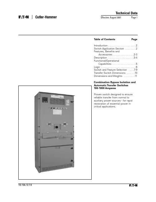
Technical Data Effective: August 2007Page 1T able of Contents Page Introduction . . . . . . . . . . . . . . . . . . . .2 Switch Application Section . . . . . . . .2 Features, Benefits andAccessories . . . . . . . . . . . . . . .2-3 Description . . . . . . . . . . . . . . . . . . .3-4 Functional/OperationalCapabilities . . . . . . . . . . . . . . . . .5 Logic . . . . . . . . . . . . . . . . . . . . . . . . .6 Switch and Feature Selection . . . .7-9 Transfer Switch Dimensions . . . . . .10 Dimensions and Weights . . . . . . . .11 Combination Bypass Isolation and Automatic T ransfer Switches100-1000 AmperesProven switch designed to ensure reliable transfer from normal to auxiliary power sources - for rapid restoration of essential power in critical applications.IntroductionCombination Bypass Isolation and Automatic Transfer Switches are designed for applications where preventative maintenance,inspection and testing must be accomplished while maintaining continuity of power to the load.This is typically required in standby power situations that require safe maintenance of the system with minimal disruption of power. Combination BypassIsolation and Automatic Transfer Switches meet or exceed allindustry standards for endurance,reliability and performance.Cutler-Hammer Maintenance Bypass Isolation Transfer Switches meet or exceed allindustry standards for endurance,reliability, and performance. They are listed under CSA 22.2 No 178and UL1008 standards for transfer switches.Design Highlights •Overcurrent protection available •Simple test circuit •Designed to safelywithstand fault currents •Manufactured in an ISO 9002/14001 facility and designed in an ISO 9001 facility•Seismic qualified for UBC Zone 4Switch Application SectionTransfer switch equipment offers flexibility and versatility to the system designer and user.Cutler-Hammer Bypass Isolation Transfer Switches are offered in two basic designs, doublesided (USA and Canada) and single-sided configuration (Canada Only). A double-sided bypass isolation transfer switchcompletely isolates the transfer switch while providing the user the ability to bypass the load to only one source, either the utility source or the emergency source as specified when ordered. In accordance with CSA C282-00(Institutional and ResidentialBuilding Occupancy Group B and Group C) require as a minimum a single sided bypass on emergency supply.All Switches include the basic features necessary for normal operation as standard ( see next page). Cutler-Hammer also offers an extensive array of optional features and accessories that permits the user to customize a new transfer switch to match the application. The customization process is simple. Select theappropriate catalogue number for your application from the charts.Then choose any optional features or accessories needed to complete the project requirements.Technical DataEffective: August 2007Page 2Bypass Isolation Transfer Switches 100 - 1000 Amperes25kA 35kA 42kA 50kA 65kA 100kA 200kA 30 - 2002,3,4Any*Any*Any*Any*Any*Any*FDC,JDC,KDC 2252Any*Any*Any*Any*Any*Any*FDC,JDC,KDC 3002,3,4Any*Any*Any*Any*Any*Any*KDC 4002,3,4Any*Any*Any*Any*Any*Any*KDC 6002,3,4Any*Any*Any*Any*Any*Any*LDC 800 - 10002,3,4Any*Any*Any*Any*Any*Any*---(FDB/FD)+LFD 150kA FDC,JDC,KDC FCL***,LCL***200 - 3002,3,4Any*Any*Any*Any*Any*KDC,NB-TP**LCL***4002,3,4Any*Any*Any*Any*Any*------6002,3Any*Any*Any*Any*Any*NB-TP ---8002,3Any*Any*Any*Any*---NB-TP ---600 - 10004Any*Any*Any*Any*---------10002,3Any*Any*Any*Any*---------(FD/FDB)+LFD (FD/FDB)+LFD (FD/FDB)+LFD (FD/FDB)+LFD KDC KDC KDC LCL 200 - 3002,3,4Any*Any*Any*KDC KDC LCL ---4002,3,4Any*Any*Any*KDC KDC ------6002,3Any*Any*Any*LDC ---------6004Any*------------------800 - 10002,3,4Any*------------------*Any manufacturers' breaker ** with P12 limiter *** 150kA maximum 04/16/07Any*Any*Any*480Y/277 and48030 - 1502,3,4Any*Any*WWhen protected by an upstream, any manufacturers' breaker or Cutler-Hammer circuit breaker as shown, the transfer switch is rated for use on a circuit capable of delivering not more than the RMS Symmetrical amps at the voltage shown below.Maximum fault level available at upstream device (kA symmetrical)Upstream any manufacturers' breaker or Cutler-Hammer circuit breaker typeVoltageTransfer Switch Ampere Rating Number of PolesSwitched---600Y/347 and60030 - 150120/240 and 240, 208Y/1202,3,4Any*Any*Features,Benefits and accessoriesSuperior main Contact Structure The combination Bypass Isolation and Automatic transfer Switch meets or exceeds the standards set forth in UL 1008, UL489, CSA 22.2 No 178 and CSA 22.2 No 5.No other transfer switchmanufacturer has met the rigid testing requirements of this combination of pletely enclosed contactsprovide both safety and reliability.They also ensure the integrity of the contact assemblies and minimize the need for periodic maintenance of the contacts,reducing downtime and maintenance time.Long-Life DesignMain contacts employ developed DE-ION® arc quenchers andcontact arcing horns for extended in-service life and reduced pitting and burning of contact services.Simple,Reliable OperationThe automatic transfer switch is operated by a single,unidirectional gear motor transfermechanism that receives itspower from the source to which is being transferred. Bypass and Isolating Mechanisms aremanually operated by handles which ensure true quick-break,quick-make operation under full load conditions.Secure IsolationInterlocking of ATS main contacts ensure that both power sources cannot be simultaneouslyconnected to the load. Bypass switches are mechanicallyinterlocked to prevent paralleling of sources.Versatile ControlControl Logic Panel interconnects with Power Switching Panel via insulated keyed plug connectors to permit total isolation ofcontrols for routine maintenance.Engine Starting ContactProvides a 10 ampere, 30 Vdc contact closure to initiate engine starting upon failure of the Normal Power Source. Thisfeature, specifically designed for low current applications, is wired to red terminal blocks on the identification and maintenance.Full Phase ProtectionProvides phase failure protection on each phase of Normal Power Source. Should voltage drop below a pre-selected, fullyadjustable value on any phase, a signal is sent to initiate engine start.Time Delay Normal to Emergency Delays the retransfer from Emergency/Standby PowerSource to Normal Power Source to permit stabilization of the Normal Power source before retransfer is made. Timing is adjustable 0-30 minutes and begins when the Normal Power Source appears. If theEmergency/Standby PowerSource is immediate, overriding the time delay.Time Delay Engine Cooldown Permits the engine to continue to run unloaded after transfer to the Normal Power Source has been made. Timing is adjustable 0-30minutes and begins when retransfer is completed.Technical DataEffective: August 2007Page 3100kA 200kA---J, T 200AJ, T ---400A R J, T 400A J, T ---600A J, T R 600A L ---1200A L ---800A ---L 1600A800 - 10002,3,4---L 1600A---J, T 200AJ,T ---400A R J, T 400A J, T ---600A J, T R 600A L ---1200A L ---800A ---L 1600A6004---L 1600A800 - 10002,3,4---L 1600A04/10/07When protected by an upstream fuse type shown, the transfer switch is rated for use on a circuit capable of delivering not more than the RMS Symmetrical amps at the voltage shown below.VoltageTransfer Switch Ampere RatingNumber of PolesSwitchedUpstream Fuse Type Maximum fault level available at upstream deviceMax FuseAmperes (kA symmetrical)120/240 and 240, 208Y/12030 - 2252,3,44002,3,43002,3,46002,3,4480Y/277, 480, 600Y/347 and60030 - 1502,3,4200 - 3002,3,44002,3,46002,3Fully rated NeutralProvides a fully rated solid neutral for all 2 and 3 pole switches. All 4 pole switches are supplied with switched neutral contacts of identical construction and rating as the power poles and are mounted on the power contact shaft, integral to the completely enclose contact assemblies.Emergency/Standby Source MonitoringRelay monitor prevents transfer from the Normal Power Source to the Emergency/Standby Power Source until that source has attained 90% of nominal voltage and frequency. In addition, when the switch is in theEmergency/Standby position and that source falls outside the monitored parameters, a load retransfer is initiated to the Normal Power Source if it is present.Indicating LightsIndicate source availability, switch position, transfer switch isolation position, and bypass modes.Description:Switch Operation:Bypass to Normal (Utility power) Turn “ENGINE SELECTOR” switch to “OFF” positionPlace isolating handle mechanism in “OFF”positionPosition bypass switch interlocking plate for “NORMAL BYPASS” operationPlace “NORMAL BYPASS” switch to “ON” position Bypass to emergency (standbypower)Turn “ENGINE SELECTOR” switchto “RUN” positionPlace isolating handle mechanismin “OFF”positionPosition bypass switch interlockingplate for “EMERGENCY BYPASS”operationPlace “EMERGENCY BYPASS”switch to “ON” positionReturn to Normal OperationPlace appropriate bypass switchin “OFF”positionPlace isolating handle mechanismin the “ON”positionTurn “ENGINE”switch to “AUTO”positionBenefitsThe combination Bypass Isolationand Automatic Transfer Switcheliminates all of the complicateddrawout mechanisms required oncompetitive products for totalisolation of the transfer switch,and instead utilizes foolproofmechanical interlocking platecombined with a positive TotalIsolation Mechanism. The result isthe safest, easiest-to-operatebypass isolation switch availablein the marketplace today.When the transfer switch is in theIsolated position, complete testingof the ATS can be accomplishedvia a special insulated keyedconnector.This allows theoperator to completely test theentire operating sequence of theATS while maintaining power tothe connected load.The combination Bypass Isolationand Automatic Transfer Switchutilizes modified moulded caseswitches, designed specifically forhigh duty repetitive load transfer,as a means to bypass and totallyisolate the transfer switch. Thisdevice provides for a reliable ,rugged installation that canwithstand very high level shortcircuits. In addition, 100-600ampere units utilize Series CTechnology that offers a highestWithstand, Closing andInterrupting Rating available inthe marketplace today.Technical Data Effective: August 2007Page 4Bypass Isolation Transfer Switches100 - 1000 AmperesEffective: August 2007Page 5Figure 2: Double Sided Bypass Double Line Diagram (available in Canada & USA)Functional and Operational CapabilitiesOur overall design criteria is to provide a you with a Combination Bypass Isolation and Automatic transfer Switch that offers theutmost in flexibility, reliability and value. The long list of standards and codes below illustrates the versatility of our unit. Thecombination Bypass Isolation and Automatic Transfer Switch meets or exceeds many national and international standards. It is also designed and built in accordance with the following:CSA 22.2 No 178 and UL1008-Standard for Automatic Transfer Switches.CSA 22.2 No 5 and UL489 -Standard for Moulded Case Circuit Breakers and Moulded Case Switches.CSA C282-Emergency Electrical supply for building.ISO 9000-International Organization for Standards.ISO 4001-Manufacturing Facility.UBC -Uniform building code for Seismic Zone 4Basic Switch DesignCombination Bypass Isolation and automatic Transfer Switchesconsist of Normal Bypass Switch,Emergency Bypass Switch, aPositive Isolating Mechanism and an Automatic Transfer Switch. All subassemblies are testedindividually, and the complete assembly is subjected to full operational testing beforeshipment from Cutler-Hammer’s Transfer Switch manufacturing facility.Technical DataEffective: August 2007Page 6Double Sided Bypass Isolation Transfer Switch shownLogic ControllerEmergency Bypass SwitchNormal Bypass SwitchIsolating MechanismAutomatic Transfer SwitchLogicApplication VersatilityWhether the application calls for open or closed transition, manual or automatic operation, Cutler-Hammer has the right logic controller for the task. ATC300 and ATC600 Controller has set a new standard for transfer switch technology featuring:•Microprocessor- based logic •Digital LCD display•Field programmable set-points •Voltmeter and frequency meter •True rms voltage sensing •Mimic BUS/LED display •Delayed transition capability •Plant exerciserAutomatic T ransfer Open T ransitionAvailable with:•Time delayed neutral•Pre-transfer signal•Manual Re-transfer (ATC600only)•In Phase monitor (ATC600 only)•Delayed transition low voltage decay (ATC600 only)Ease of maintenanceKeyed quick disconnect plugs areprovided for easy and completeisolation of the control circuitry.Maintenance can be performed onthe logic independent from thepower sections and still allow theuser to manually transfer powerunder full load conditions.Technical DataEffective: August 2007Page 7Logic Disconnect PlugsEase of MaintenanceAutomatic Transfer Open TransitionMP1 ControllerKeyed quick-disconnect plugs are pro-vided for easy and complete isolationof the control circuitry.Maintenance can be performed onthe logic independent from the powersections and still allow the user tomanually transfer power under fullload conditions.Available with:Time delayed neutralPre-transfer signalPreferred Source SelectionManual Re-tansferTechnical DataEffective: August 2007Page 8Catalogue Number Selection Guide (Canada transfer switches only)1.Single Sided Bypass Isolation Transfer Switches come standard with emergency bypass. If normal bypass is required, please specify when ordering.2.In accordance with CSA C282-00, Institutional and residential building occupancy (Group B and Group C) require a minimum a Single SidedBypass on Emergency supply.Catalogue Number Selection Guide (USA transfer switches only)Technical DataEffective: August 2007Page 9Table 2: Switch and Feature SelectionATC300 ATC600 Std.Std. Std.Std.Std. Std. Std. Std. Std. Std. Std. Std. Std. Std. Std. O Std. Std. Std. O O O O O Std. Std. Std.Std.Std. Std. O O O O N/A O N/A O Std.Std.O O Std.Std.O O Std.Std.O O Std.Std.O O O O O O O O O O O O O O O O O O O O O O Std.Std.Std. Std. O O O O ATS FEATURE Description1Time Delay Normal to Emergency (TDNE)2Time Delay Engine Start (TDES) 3Time Delay Emergency to Normal (TDEN)4Time Delay Engine Cooldown (TDEC) 5H Source2 - Phase Reversal Sensing5J Source2 - All Phase Undervoltage/Underfrequency 5K Source2 - All Phase Overvoltage/Overfrequency5L Source2 - All Phase Voltage unbalance and phase loss S6B Test Operator (Controller Faceplate)Std. Std.6D 2-Position Selector Selector Switch (Test/Auto)Std. O 6H 4-Position Selector Switch (Test/Auto/Manual/Engine Start)O O 6J Keyed 4-Position Selector Switch (Test/Auto/Manual/Engine Start) OO 7A Time Delay Emergency Fail (TDEF) Adjustable 0 - 6 Seconds)S 8C Time Delay Bypass EN Pushbutton (Controller Faceplate) Std.Std. 8D Time Delay Bypass NE Pushbutton (Controller Faceplate) Std. Std. 9B Maintenance / Electrical Operator Isolator Selector SwitchO O 9D Keyed Maintenance / Electrical Operator Isolator Selector Switch O O 10B Preferred Source Selector - Utility to Utility or Utility to Generator N/A O 10D Preferred Source Selector - Generator to Generator N/A O 12C Source1 Connected (LED)S 12CC Source1 Connected (30mm Pilot Light) O O 12D Source2 Connected (LED)S 12DD Source2 Connected (30mm Pilot Light) O O 12G Source1 Available (LED)S 12GG Source1 Available (30mm Pilot Light) O O 12H Source2 Available (LED)S 12HH Source2 Available (30mm Pilot Light)O O 12L Source1 Device Tripped (Selectable with option 16 only) O O 12M Source2 Device Tripped (Selectable with option 16 only) O O 14A Source1 Connected Auxiliary Relay (2NO/2NC Form C)O O 14B Source2 Connected Auxiliary Relay (2NO/2NC Form C)O O 14C Source1 Available (4NO/4NC Form C)O O 14D Source2 Available (4NO/4NC Form C)O O 14E Source1 Available (1NO/1NC Form C)O O 14F Source2 Available (1NO/1NC Form C)O O 14G Source1 Available (2NO/2NC Form C)O O 14H Source2 Available (2NO/2NC Form C)O O 15A Source1 Connected (2NO/2NC Form C)Std.Std. 15B Source2 Connected (2NO/2NC Form C)Std. Std. 15C Source1 Connected (4NO/4NC Form C)O O 15D Source2 Connected (4NO/4NC Form C)OOTTechnical DataEffective: August 2007Page 10 Table 2: Switch and Feature SelectionTechnical DataEffective: August 2007Page 11Table 2: Switch and Feature SelectionO O OOREFER REFERN/A O N/A O N/A O N/A O N/A O N/A O N/A O N/A O N/A O N/A O N/A N/A N/A N/A N/A N/A N/A O N/A O O O O O OO REFER REFER REFER REFER O O O O O O OO REFER REFER REFER REFER REFER REFER REFER REFER REFER REFER REFER REFER REFER REFER REFER REFER REFERREFER41A 100W Space Heater (c/w:Thermostat)41C 400W Space Heater (c/w:Thermostat)42Seismic Zone 4Certified (CBC,IBC,UBC,BOCA)45A Load Sequencing Contacts (1)45B Load Sequencing Contacts (2)45C Load Sequencing Contacts (3)45D Load Sequencing Contacts (4)45E Load Sequencing Contacts (5)45F Load Sequencing Contacts (6)45G Load Sequencing Contacts (7)45H Load Sequencing Contacts (8)45I Load Sequencing Contacts (9)45J Load Sequencing Contacts (10)47C Closed Transition In-Phase with default to Load Voltage Decay 47D Closed Transition OnlyN 47E Closed Transition In-Phase with default to Time Delay Neutral N 48A Communications -IPONI ModuleN 48F Communications -MPONI Module (MODBUS)N 51D150kA -Clipper device Connected to Source 1O 51E180kA -Clipper device Connected to Source 1O 51F1100kA -Clipper device Connected to Source 1O 51G150kA -CHSP device Connected to Source 1(240/120Vac single phase Only)R 51H175kA -CHSP device Connected to Source 1(240/120Vac single phase Only)R 51J4Telephone/Modem/DSL (4Lines Total)O 51K4Cable TV/Satellite Cable/Cable Modem (2Lines Total)Lines Total)O 51M4A 12Vdc Generator Start Circuit Protection O 51M4B 24Vdc Generator Start Circuit ProtectionO51NA151na1.100KA Surge Device w/Advisor Source1R 51NN151nn1.100KA Surge Device w/NetVisor Source 1R 51NS151ns1.100KA Surge Device w/SuperVisor Source 1R 51NS151sn1.200KA Surge Device w/NetVisor Source 1R 51QA151qa1.160KA Surge Device w/Advisor Source1R 51QN151qn1.160KA Surge Device w/NetVisor Source 1R 51QS151qs1.160KA Surge Device w/SuperVisor Source 1R 51SA151sa1.200KA Surge Device w/Advisor Source1R 51SS151ss1.200KA Surge Device w/SuperVisor Source 1R Std.=Standard Option on ControllerO =Optional*=Customer selects required transfer mode of operation.REFER =Please refer to Eaton sales office or BidmanagerÆpricing tool.N/A =Feature "Not Available"with selected controller.Technical DataEffective: August 2007Page 12Transfer Switch Dimensions in Inches (mm)Technical Data Effective: August 2007Page 13M a x M a x S w i t c h C S A A m p s V o lt sF r a m e B y p a s s F r a m e A B C D E F GH I J 150480F F 21/53382.5/20952.4/615.3/1357.5/19125.5/64824.5/62330/96579.5/201918/457150600F F 21/53382.5/20952.4/615.3/1357.5/19125.5/64824.5/62330/96579.5/201918/457200240F F 21/53382.5/20952.4/615.3/1357.5/19125.5/64824.5/62330/96579.5/201918/457225*240F F 21/53382.5/20952.4/615.3/1357.5/19125.5/64824.5/62330/96579.5/201918/457300480K K 21/53382.5/20952.4/615.3/1357.5/19133.2/84324.5/62338/96579.5/201918/457300600K K 21/53382.5/20952.4/615.3/1357.5/19133.2/84324.5/62338/96579.5/201918/457400240K K 21/53382.5/20952.4/615.3/1357.5/19133.2/84324.5/62338/96579.5/201918/457400480L K 21/53382.5/20952.4/615.3/1357.5/19133.2/84324.5/62338/96579.5/201918/457400600L K 21/53382.5/20952.4/615.3/1357.5/19133.2/84324.5/62338/96579.5/201918/457600240L L 21/53382.5/20952.4/615.3/1357.5/19133.2/84324.5/62338/96579.5/201918/457600480M L 21/53382.5/20952.4/615.3/1357.5/19133.2/84324.5/62338/96579.5/201918/457600600M L 21/53382.5/20952.4/615.3/1357.5/19133.2/84324.5/62338/96579.5/201918/457800240N B M D 27.12/68994.5/23252.4/615.3/13513.5/34333.2/84330.5/77538/96591.5/232424/610800480N B M D 27.12/68994.5/23252.4/615.3/13513.5/34333.2/84330.5/77538/96591.5/232424/610800600N B M D 27.12/68994.5/23252.4/615.3/13513.5/34333.2/84330.5/77538/96591.5/232424/6101000240N B N D 27.12/68994.5/23252.4/615.3/13513.5/34333.2/84330.5/77538/96591.5/232424/6101000480N B N D 27.12/68994.5/23252.4/615.3/13513.5/34333.2/84330.5/77538/96591.5/232424/6101000600N B N D 27.12/68994.5/23252.4/615.3/13513.5/34333.2/84330.5/77538/96591.5/232424/610M a x M a x S w i t c h C S A A m p sV o l t s F r a m e B y p a s s F r a m eA B C D E F GHIJ150480F F 21/53382.5/20952.4/615.3/1357.5/19125.5/64824.5/62330/96579.5/201918/457150600F F 21/53382.5/20952.4/615.3/1357.5/19125.5/64824.5/62330/96579.5/201918/457200240F F 21/53382.5/20952.4/615.3/1357.5/19125.5/64824.5/62330/96579.5/201918/457300480K K 21/53382.5/20952.4/615.3/1357.5/19133.2/84324.5/62338/96579.5/201918/457300600K K 21/53382.5/20952.4/615.3/1357.5/19133.2/84324.5/62338/96579.5/201918/457400240K K 21/53382.5/20952.4/615.3/1357.5/19133.2/84324.5/62338/96579.5/201918/457400480L K 21/53382.5/20952.4/615.3/1357.5/19133.2/84324.5/62338/96579.5/201918/457400600L K 21/53382.5/20952.4/615.3/1357.5/19133.2/84324.5/62338/96579.5/201918/457600240L L 21/53382.5/20952.4/615.3/1357.5/19143.2/109724.5/62348/121979.5/201918/457600480N B N D 27.12/68994.5/23252.4/615.3/13513.5/34343.2/109730.5/77548/121991.5/232424/610600600N B N D 27.12/68994.5/23252.4/615.3/13513.5/34343.2/109730.5/77548/121991.5/232424/610800240N B N D 27.12/68994.5/23252.4/615.3/13513.5/34343.2/109730.5/77548/121991.5/232424/610800480N B N D 27.12/68994.5/23252.4/615.3/13513.5/34343.2/109730.5/77548/121991.5/232424/610800600N B N D 27.12/68994.5/23252.4/615.3/13513.5/34343.2/109730.5/77548/121991.5/232424/6101000240N B N D 27.12/68994.5/23252.4/615.3/13513.5/34343.2/109730.5/77548/121991.5/232424/6101000480N B N D 27.12/68994.5/23252.4/615.3/13513.5/34343.2/109730.5/77548/121991.5/232424/6101000600N B N D 27.12/68994.5/23252.4/615.3/13513.5/34343.2/109730.5/77548/121991.5/232424/610*S i n g l e P h a s e O n l yB Y P A S S I S O L A T I O N A T S (4P O L E )D I M E N S I O N S (I NC H E S /M M )B Y P A S S I S O L A T I O N A T S (2&3P O L E )D I ME N S I O N S (I N C H E S /M M )Technical DataEffective: August 2007Page 14C S A C 22.2S p e c 178C e r t i f i e d A T S。
agilent u1701b 双屏手持式电容测量仪 快速入门指南说明书
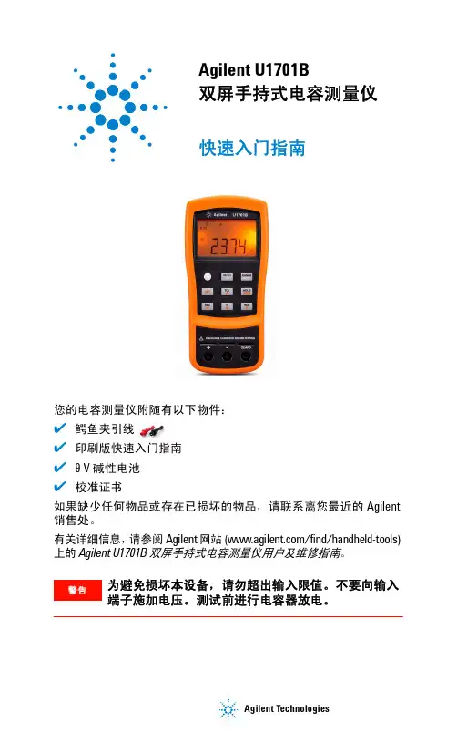
Agilent TechnologiesAgilent U1701B双屏手持式电容测量仪快速入门指南您的电容测量仪附随有以下物件:✔鳄鱼夹引线 ✔印刷版快速入门指南✔9 V 碱性电池✔校准证书如果缺少任何物品或存在已损坏的物品,请联系离您最近的 Agilent 销售处。
有关详细信息,请参阅 Agilent 网站 (/find/handheld-tools) 上的 Agilent U1701B 双屏手持式电容测量仪用户及维修指南。
为避免损坏本设备,请勿超出输入限值。
不要向输入端子施加电压。
测试前进行电容器放电。
U1701B 快速入门指南电容测量步骤:1按以开启此仪表。
1要测定电容,请保持测试引线处于开路状态,然后按,以除去仪表和引线的残余电容。
2将电容器脚分别插入 + 和 – 输入端子。
请确保电容器脚的极性正确。
3将手从电容器移开,以开始测试。
4读取显示屏上的测量值。
CAUTION 小心在测试中为避免对测量仪或设备造成损坏,请在测量电容之前,断开电路连接,并对电容器放电。
U1701B 快速入门指南特征与功能编号键功能1电源开启/关闭仪器2SET 设置对比模式的上/下限3REC 静态记录模式4对比模式5TOL 容差模式6REL 相对模式7HOLD SAVE 数据保持将设置值存储到存储器中8RANGE AUTO 手动选择范围自动选择范围9HI/LO上/下限背光显示屏854123976U1701B 快速入门指南如何进入设置模式按住以将仪器从 OFF 状态开启。
听到蜂鸣声时释放 ,仪器随后将进入设置模式。
即使在仪器关闭之后,这些参数也将保留在非易失性存储器中。
要在设置模式下配置相关参数,请确保遵循下列步骤:1按 (向左键)或 (向右键)选择要设置的菜单项。
2按(向上键)或(向下键)更改参数。
3按选择要调整的数字,选定的数字将会闪烁。
4按住 1秒钟以上以保存设置。
5按住1 秒钟以上以退出设置模式。
特征与功能操作步骤开启或关闭电源按 启用数据保持功能按 触发保持下一读取数即刻按退出数据保持模式按住 1 秒钟以上启用记录功能•当记录了一个新的 MAX 或 MIN 值时,蜂鸣器将发出蜂鸣声。
多功能集合式电表 DPM-C510 操作手册说明书
中达电通公司版权所有如有改动,恕不另行通知绵密网络 专业服务中达电通已建立了70余个分支机构及服务网点,并塑建训练有素的专业团队,提供客户最满意的服务,公司技术人员能在2小时内回应您的问题,并在48小时内提供所需服务。
400 - 820 - 9595沈阳电话:(024)2334-1160哈尔滨电话:(0451)5366-5568长春电话:(0431)8892-5060呼和浩特电话:(0471)6297-808北京电话:(010)8225-3225天津电话:(022)2301-5082济南电话:(0531)8690-6277太原电话:(0351)4039-485郑州电话:(0371)6384-2772石家庄电话:(0311)8666-7337上海电话:(021)6301-2827南京电话:(025)8334-6585杭州电话:(0571)8882-0610合肥电话 :(0551)6281-6777武汉电话:(027)8544-8475南昌电话:(0791)8625-5010成都电话:(028)8434-2075长沙电话:(0731)8549-9156重庆电话:(023)8806-0306 昆明电话:(0871)6313-7362广州电话:(020)3879-2175厦门电话:(0592)5313-601南宁电话:(0771)2621-501乌鲁木齐电话:(0991)4678-141兰州电话:(0931)6406-725西安电话:(029)8836-0780贵阳电话:(0851)8690-1374福州电话:(0591)8755-1305地址:上海市浦东新区民夏路238号邮编:201209电话:( 021 )5863-5678传真:( 021 )5863-0003网址: 扫一扫,关注官方微信DPM-093AM10-012021/11/01多功能集合式电表DPM-C510操作手册多功能集合式电表DPM-C510操作手册多功能控制型电表DPM-C510操作手册目录第1章产品概述1.1 序言.................................................................................... 1-2 1.2 外观及说明............................................................................ 1-2 1.3 警语与规范............................................................................ 1-3第2章规格说明2.1 电气规格 .............................................................................. 2-2 2.2 通讯规格 .............................................................................. 2-3 2.3 操作接口 .............................................................................. 2-42.3.1界面树形图....................................................................... 2-5 2.4 外观尺寸 .............................................................................. 2-6第3章安装说明3.1 安装方式 .............................................................................. 3-23.1.1安装环境 ......................................................................... 3-23.1.2注意事项 ......................................................................... 3-2 3.2 基本检测 .............................................................................. 3-4 3.3 接线说明 .............................................................................. 3-43.3.1线路接线图....................................................................... 3-43.3.2通讯特性 ......................................................................... 3-6第4章操作说明4.1 一般操作 .............................................................................. 4-24.1.1观看量测数据.................................................................... 4-2 4.2 设定操作 .............................................................................. 4-2i4.2.1 密码锁(PASS) .............................................................. 4-24.2.2 通讯站号设定(id)........................................................... 4-34.2.3 通讯波特率设定(bAUd)................................................... 4-34.2.4 同位设定(PRty) ............................................................ 4-34.2.5 系统设定(tyPE)............................................................. 4-34.2.6 一次侧比流器设定(Ct.PR)................................................ 4-44.2.7 比流器设定(Ct.SE) ........................................................ 4-44.2.8 重置设定(RSt).............................................................. 4-44.2.9 修改密码锁(Pwd) .......................................................... 4-54.2.10 电表信息(inFo)........................................................... 4-5第5章参数与功能5.1 参数一览表........................................................................... 5-25.2 Modbus通讯........................................................................ 5-65.2.1 支持的Modbus功能码....................................................... 5-65.2.2 Modbus通讯协议 ............................................................. 5-6第6章异常信息6.1 异常信息一览表...................................................................... 6-2附录A 配件A.1 DCTMC系列......................................................................... A-2A.2 DCTCS系列......................................................................... A-3A.3 DCT1000系列...................................................................... A-4A.4 DCT2000系列...................................................................... A-6 ii多功能控制型电表DPM-C510操作手册版本修订一览表版本变更内容发行日期第一版第一版发行2021/11/91第1章产品概述目录1.1 序言................................................................................... 1-2 1.2 外观及说明........................................................................... 1-2 1.3 警语与规范........................................................................... 1-31-1多功能控制型电表DPM-C510操作手册 1-2 1.1 序言感谢您使用本产品,本电表接口安装手册提供DPM-C510电表的相关信息。
CRIO-4010 单相、三相全参数交流 电量采集模块 用户手册说明书
CRIO-4010单相、三相全参数交流电量采集模块用户手册版本号:Q7-30-02修订日期:2016-11-1国控精仪(北京)科技有限公司2016年版权所有本软件文档及相关套件均属国控精仪(北京)科技有限公司所有,包含专利信息,其知识产权受国家法律保护,除非本公司书面授权许可,其他公司、组织不得非法使用和拷贝。
为提高产品的性能、可靠性,本文档中的信息如有完善或修改,恕不另行通知,客户可从公司网站下载或致电我们通过电子邮件索取,制造商无需作成承诺和承担责任。
客户使用产品和软件文档进行设备调试和生产时,应进行可靠性、功能性等全面测试,方可进行整体设备的运行或交付。
我们提供7*24电话技术支持服务,及时解答客户问题。
如何从国控精仪获得技术服务我们将为客户提供满意全面的技术服务。
请您通过以下信息联系我们。
国控精仪公司信息网址: 英文中文销售服务: **************销售分机:801 电话: 400 9936 400 ************传真: ************地址: 北京市海淀区安宁庄东路18号2号办公楼420-423室请将您下列的信息通过邮件或传真发送给我们1概述...................................................................................................................................... - 1 -1.1产品特性.................................................................................................................. - 1 -1.2产品应用.................................................................................................................. - 1 -1.3产品详细指标.......................................................................................................... - 2 -1.3.1电量参数...................................................................................................... - 2 -1.3.2系统稳定时间.............................................................................................. - 2 -1.3.3物理特征...................................................................................................... - 3 -1.3.4产品功耗(典型值) ..................................................................................... - 3 -1.3.5工作环境...................................................................................................... - 3 -1.3.6存储环境...................................................................................................... - 3 -1.4软件支持.................................................................................................................. - 3 -2设备安装.............................................................................................................................. - 5 -2.1产品开箱.................................................................................................................. - 5 -2.2软件安装.................................................................................................................. - 5 -2.3产品布局图.............................................................................................................. - 6 -3信号连接说明...................................................................................................................... - 7 -3.1连接器管脚分配...................................................................................................... - 7 -3.2电源与通讯连接...................................................................................................... - 8 -3.3信号连接.................................................................................................................. - 9 -4 模拟量输入(AI)模块功能码........................................................................................ - 10 -4.1读保持寄存器........................................................................................................ - 10 -4.2读输入寄存器........................................................................................................ - 11 -4.3设置单个保持寄存器............................................................................................ - 13 -4.4设置多个保持寄存器............................................................................................ - 13 -5产品注意事项、保修、校准............................................................................................ - 15 -图2-1 CRIO4010产品图................................................................................................... - 6 -图3-1 电源与通讯接线图 ................................................................................................ - 8 -图3-2 单相电示意图 ........................................................................................................ - 9 -图3-3 三相电示意图 ........................................................................................................ - 9 -表3-1 16P端子标注 .......................................................................................................... - 8 -1概述CRIO-4010是基于RS485的高性能通信模块。
LB Management 电子开关芯 单通道 产品号 1704ESE 使用说明说明书
电子开关芯 单通道产品号 : 1704ESE使用说明1安全指南电气设备的安装和连接只允许由电气专业人员执行。
可能引发严重伤害、火灾或财物损失。
请完整阅读并遵守操作说明。
电击危险。
在对设备或负载施工前先安全断开。
电击危险。
设备不应断开。
即使在关闭仪器的情况下,负载也没有断开电源。
当设置的运行方式与负载类型不匹配时,可能导致毁坏危险。
在连接或更换负载时正确设置运行方式。
火险。
在使用感应变压器操作时,必须遵守每种变压器相应制造商的使用说明。
只能使用符合EN 61558-2-6(VDE 0570,第 2-6 部分)的安全隔离变压器。
该说明书属于产品的组成部分,必须由最终用户妥善保管。
2正常应用–配置 LB 管理系统中合适的顶盖进行使用–根据 DIN 49073 安装至设备插座内有零线情况下运行–白炽灯,HV卤素灯,带卤素或 LED 灯的电子或感应式变压器,可切换或可调光的 HV LED 或紧凑型荧光灯,电热执行器与室温控制器插件的开关–结合室温控制器插件,控制电热执行器无零线情况下运行–接通白炽灯、高压卤素灯、卤素灯或 LED 灯的电子变压器、卤素灯或 LED 灯的可调光感应变压器、高压 LED 灯或节能灯,并进行调光产品特性–通过节能型软启动接通–可以连接分站–最迟 7 秒后长久切断电子短路保护–电子超温保护通过发电厂集控脉冲信号可以使连接的灯具亮起。
这并不是设备的缺陷。
有零线情况下运行–设备具有外线和零线,因此,没有相位导通或相位导通。
–结合室温控制器插件,可实现电热执行器的静音切换无零线情况下运行–设备通过外线和相连的负载供给,根据相位导通原理工作–自动或手动设置与负载相匹配的运行方式–通过 LED 显示设置的运行方式可能在识别负载时短暂闪烁。
识别负载期间不得进行操作。
3操作本说明书介绍了按键端的使用。
相应套筒的说明书中介绍其它套筒的操作。
通过带电键套或按键的双线分机进行操作基本符合主机上的操作。
氢气流量计100系列
100®Smart-Trak 系列指导手册Smart-Trak® 100系列质量流量计和调节仪指导手册A版 2003.6亚洲总部中国广州江南大道中100号中广大厦 2303室电话: +86 203435 4870 传真:+86 203435 4872顾客需知 美国Sierra仪表公司对将任何标准质量流量计及调节仪应用于氧气领域所带来的破坏及人身伤害概不负责。
你必须检定该质量流量计及调节仪是否适合你的氧气应用领域,并将其清洁到你的氧气应用领域所要求的程度。
版权所有(Sierra仪表公司 2003)未获得Sierra仪表公司的书面许可,本手册的任何部分严禁以任何格式和任何方法复制、发行、传播、转录、存储到检索系统中或者翻译成任何自然语言或计算机语言。
本手册的内容如有变动,恕不另行通知。
商标Smart-Trak TM和Dia-A-Gas TM为Sierra仪表公司注册商标。
此手册中提到的其它产品及公司名为各厂家商标或者商品名目 录第1章 简介简介……...……………………………………………..……………………………..1-1手册的使用……………………………………………………………...……..1-1 安全信息…………….…………………………………………………..……..1-1 收贷…………………………………………………………………….………1-2 本手册使用名词定义……………………………………………….…………1-2 Smart-Trak 流量传感器原理…………………………….…………………………1-3第2章 安装及接线安装前准备…………………………………………………………………………...2-1 Smart-Trak 数据标签……………………………………………………..………….2-1 安装前检查事项……………………………………………………………………...2-1 仪表管道安装……………………………………….….…..………………………...2-2压垫式安装…………………………………………..……………………..2-2 VCO 式安装………………………………………….………………………...2-3 VCR 式安装…………………………………….……………………………2-3 41英寸内NPT 连接…………………….………………………………………2-3 仪表机械部分安装…………………………………………………………………...2-3 仪表电气部分安装…………………………………..……………………………….2-4D 形连接头引脚分配………………………….……………………………….2-5 电源要求………………..……………………………………………………...2-6 RS-232接线……………………………………………………………………2-6第3章 模拟量操作简介…………………………………………………………………………...............3-1 质量流量计模拟量操作……………………………………………….......................3-1 质量流量调节仪模拟量操作………………………………………………………...3-1 Smart-Trak 特点……………………………………………………………………...3-2设定点调节…………………………………………………………………….3-2 改变输出或设定信号……………………………………………………….3-2 过量程状态……………………………………………………………………3-2 手控阀关闭…………………………………………………………………..3-2 手控阀清洁………………………………………………………………….3-3第4章 导引模块操作导引模块操作简介…………………………………………………………………...4-1 导引模地特点及性能介绍……………………………………………….................4-1 质量流量度导引模块操作…………………………………………………………...4-2质量流量调节仪导引模块操作…………………………………………………...…4-3使用导引块菜单及用户界面…………………………………………………...…4-4导引模块界面图……………………..…………………………………………….…4-5上级屏幕(显示)……………………………………………………………………….4-5 质量流量屏………………………………………………………………….…4-6设定屏……………..………………………………………………..……...4-6阀门位置屏………………………………………………………………….....4-6量程屏…………………………………………………………………...……..4-7 下级屏幕(改变参数)………………………………………………………...………..4-7 进入下级屏幕…………………………………………………………………4-7密码屏…………..………………………………………….…………………..4-8使用下级屏幕修改设置………………………………………………..……...4-8修改设定值屏…………………………………………………………..……...4-9修改单位屏…………………………….……………………………………..4-10修改气体屏(Dial-A-Gas)……………………………………………………..4-11修改阀门操作(关闭,清洁)…………………………………………………..4-12修改设定源屏………………………………………………………………...4-13修改输出信号屏……………………………………………………………...4-14修改量程屏………………….………………………………………………..4-15改变密码屏…………………………………………………………………...4-16忘记密码&客户服务…………………………………………………….…..4-17故障查找和维护功能………………………………………………….……..4-18 第5章 RS-232操作(Smart-Trak软件)简介………………………………………………………………………...………..5-1Smart-Trak特点概要……………………………………………………………..5-1仪表上电………………………………………………………………….…………..5-2电脑上电………………………………………………………….………………..5-2安装Smart-Trak软件………………………………………………………………..5-2连接Smart-Trak和电脑……………………………………..……………………..5-3运行Smart-Trak软件…………………………………………..……………………..5-5使用Smart-Trak软件………………………………………………………………..5-6软件窗口的上部分…………………………………………...……………………..5-6密码部分……………………………………………….......………………………..5-7软件窗口下部分……………………………………………………………………5-7 改变设定点的值……………………………………………………………...5-7改变阀门操作(关闭,清洁)…………………………………………………5-8改变气体选项(Dial-A-Gas)…………………………………………………5-8改变单位…………………………………………………………………..5-8改变设定源……………………………………………………………...5-9改变输出信号…………………………………………………………….…..5-9改变量程……………………………………………………………………..5-9改变密码……………………………………………………………………..5-10忘记密码&客户服务….……………………………………………….……..5-10其它有用特点…...……………………………………………………..……..5-11COMM口……………………………………………………………………..5-11读调节仪参数………………………………………………….…………..5-11连网…………………………………………………………….……………..5-11PDF信息…………………………………………………….………………..5-12 第6章 技术支持及服务技术支持………………………………………………………………………….…..6-1Sierra公司网址………………………………………………………………..6-1仪表送回厂家………………………………………………………….……………..6-2 附录A 气体表预置气体列表-Dail-A-Gas…………………………………………………………..A-1K系数计算……………………………………………………….…………………..A-1气体表及K系数……………………………………………………………………..A-2 附录B 技术参数性能参数………………………….…………………………………………………..B-1操作参数………………………………….…………………………………………..B-1物理参数………………………………………….…………………………………..B-3配选件…………………………………………………….…………………………..B-3 附录C 导引式用户接口流程图附录D HD DB-15引脚配置附录E 尺寸及安装第1章 简 介欢迎来到未来气体流量测量世界!Sierra 仪表公司(一家设计制造气体质量流量测量装置的公司,始于七十年代)的Smart-Trak100系列仪表是该公司的革新产品。
- 1、下载文档前请自行甄别文档内容的完整性,平台不提供额外的编辑、内容补充、找答案等附加服务。
- 2、"仅部分预览"的文档,不可在线预览部分如存在完整性等问题,可反馈申请退款(可完整预览的文档不适用该条件!)。
- 3、如文档侵犯您的权益,请联系客服反馈,我们会尽快为您处理(人工客服工作时间:9:00-18:30)。
ETS1701-100-Y00说明书
贺德克ETS-1701-100-Y00温度传感器说明书:
ETS1700
可用版本:
标准
ETS1700电子温度开关主要与专门为储罐安装开发的TFP100温度传感器一起使用。
4个字符的显示屏可以显示当前温度,切换点之一或最大温度值。
最高温度值分别表示自设备开机或自上次复位以来发生的最高温度。
例如,可以使用4个开关量输出来控制液压设备的加热和冷却过程。
可以通过薄膜键盘非常容易地设置彼此独立的四个开关点和复位点。
模拟量输出(4…20mA或0…10V)可集成到监视系统中(例如使用SPS)。
4位数字显示
通过按键编程简单处理
4个极限值继电器,开关点和复位点可以相互独立调节
可以选择模拟输出信号(4…20mA或0…10V)
许多有用的附加功能
可以选择安装位置(上下左右的传感器连接,键盘和显示屏可以旋转180°)
贺德克EDS-3448-5-0600-000
贺德克ETS-386-2-150-Y00
贺德克EDS-345-1-250-000 贺德克EDS-3446-3-0100-000 贺德克EDS-3446-2-0100-000 贺德克EDS-3448-5-0100-000。