meteonorm中文使用手册
蒙特苏马工作台说明书

OWNER'S MANUAL 4' ADJUSTABLE HEIGHT STEEL WORKBENCH WITH PEGBOARD BACK WALLMWB482454B LIFE ORGANIZEDMontezuma is committed to helping you succeed in both your workand personal life by being organized, prepared and equipped withthe right tools, gear and home supplies at your finger tips.Keep your life organized with Montezuma.Thank you for your purchase of this Montezuma Workbench.ATTENTIONTO REDUCE THE RISK OF INJURY, THE USER MUST READ ANDUNDERSTAND THIS INSTRUCTION MANUAL BEFORE USING THIS PRODUCT FOR THE FIRST TIME. SAVE THESE INSTRUCTIONS FOR FUTURE REFERENCE.Fill in the following information and retainthis owner's manual for future reference:MODEL(S):DATE OF PURCHASE:PLACE OF PURCHASE:RECEIPT NO:2SPECIFICATIONSMAXIMUM PRODUCT WEIGHT: 1000 lb (450 kg) of static, evenly distributed weight MAXIMUM SHELF WEIGHT: 50 lb (22.7 kg)MAXIMUM WEIGHT ON PEGBOARDS: 35 lb (15.9 kg)OVERALL DIMENSIONS:48" W x 24" D x 66.2" H (121.9 cm W x 61 cm D x 168.1 cm H)WORKBENCH DIMENSIONS:48" W x 24" D x 41" H (121.9 cm W x 61 cm D x 104 cm H)Steel frame height adjusts from 29" to 41" in 1" increments4PARTS LISTToorderreplacementparts,*****************************************************(Monday–Friday, 8:00 am–4:30 pm, CST). Have the part number and quantity ready. Replacement keys may be ordered using the code that appears on the face of the lock. Not all parts are covered under warranty. Those parts not covered can be purchased.REF DESCRIPTIONPART NUMBER QTY 1M5 x 18 mm Lag Screw 122327292M6 Hex Nut 122329693M6 x 10 mm Bolt 122328694Leveling Feet 12232645Montezuma Nameplate 1217011213545M6 Hex Nut For use with the bolts Leveling Feet For leveling the workbench M5 x 18 mm Lag ScrewUse to attach work top to frame M6 x 10 mm BoltFor frame assembly Montezuma NameplateFor attaching to the front of theworkbench29694691ASSEMBLYInstall one of the leveling feet at the bottom of each adjustable leg section.Slide each adjustable leg section onto a main leg section until you reach the desired height. Remember that the wood work top is 1.25" thick, so you will need to reduce the leg length by the 1.25" to hit your targeted height. Make sure the length of each leg is the same.Insert one cross brace so that it can be fastened together with the adjustable leg section and main leg section at the desired height, making sure all holes are lined up. Use four (4) nuts and bolts to secure the cross brace. Repeat to connect a second leg, which creates one leg assembly.Secure the leg assembly with another cross brace at the top of the legs using four (4) bolts and nuts per leg.Tighten all nuts and bolts.Repeat to create the second leg assembly, which will form the other end of the workbench.Line up the holes in the two cross bars with the holes in the top of the leg assemblies. The cross bar flange will overlap the legs at each end. Secure each cross bar to the top of each leg using two (2) nuts and bolts.Connect the braces from the front cross bar to the leg assemblies to improve stability, using two (2) nuts and bolts for each brace.Do not tighten fasteners until all legs are connected to the cross bars and braces. Once all legs are connected, use a level to make sure the frame is straight, then tighten all nuts and bolts.Attach the bottom shelf to the bottom cross braces using two (2) nuts and bolts on either side. The shelf is recessed so that a stool can be tucked under the workbench.Place the work top on a soft mat with the finished top surface facing down.Place the steel frame upside down on the work top. The work top should be flush with the back of the frame – this would be the back of your workbench. It will allow the workbench to be pushed close to the wall and leave an overhang on the front of the workbench.Center the frame, right to left.Mark the holes on the steel frame onto the bottom of the work top. Remove the steelframe. Drill pilot holds in the bottom of the work top at the locations you have marked.Place the steel frame back on the work top and secure using the screws that areincluded. Six screws are used to attach the work top to each long cross bar and four screws are used to attach the work top to each short cross brace.Turn the workbench upright and place in the location it will be used. Check to make sure the workbench is still level. If you need to adjust, use the leveling feet.Attach the Montezuma Nameplate to the right hand side of the front cross bar using the self-adhesive backing.8Build the back wall onto the workbench by slipping a column onto one back corner of the work top. The column should be nested above and below the work top. Mark the location of the holes in the bottom of the column on the bottom of the work top. Remove the column and drill pilot holes in the bottom of the work top. Set the column back in place so the work top is nested into the column and secure the column in place using the four (4) lag screws. Repeat on the other side with the remaining column.Attach the top shelf by nesting it down in the tops of each of the columns. The columns have been designed with notches to help locate the top shelf into place. Fasten the top shelf to each of the columns using two (2) nuts and bolts in the side and back of the columns.Place the column cross brace under the top shelf and secure it to each column with one (1) nut and bolt. The cross brace is notched so it will set under the top shelf and the end of the cross brace will overlap the front of each column.On the back side of the workbench, lift the pegboard panel into place. Line up the holes of the pegboard panel with the holes in the inside edge of the columns. Secure with three (3) nuts and bolts. It may be easier to complete this step with one person inserting the bolts into the holes from the front and another person in back tightening the nut. Secure the top of the pegboard panel to the top shelf with two (2) nuts and bolts. Repeat this assembly with the other side of the pegboard panel.Carefully drill pilot holes in the top of the work top that line up with the holes in the bottom of the pegboard panel. Screw the bottom of the pegboard panel into place using lag screws. Check one more time to make sure your workbench and back wall are level. Secure all fasteners and move into place. Make sure it is level in the area it will be used.MAINTENANCEPeriodically tighten all hardware and make sure workbench is level.Clean the work top with wood cleaner.SAFETYDO NOT let children play or hang on the edge of the workbench. It could tip and cause personal injury or product damage.DO NOT stand or lean on the work top. The workbench could tip and cause personal injury or product damage.DO NOT mount this product on a truck bed or any other moving object. This may cause personal injury or product damage.DO NOT alter this project in any manner. For example, do not weld external lockbars or attach electrical equipment. This may cause product damage or personal injury.Keep the product on level surfaces. The product may become unstable and tip if stored or moved on an uneven surface, which may cause personal injury or product damage.Do not place items so that they overhang the top or bottom shelves. Items could fall and cause personal injury or product damage.Do not place items that have a combined weight of over 50 lb (22.7 kg) on either of the shelves. Excess weight could result in personal injury or product damage.Do not hang items that have a combined weight of more than 35 lb (15.9 kg) on the steel pegboard panel. Excess weight could result in personal injury or product damage.MAXIMUM PRODUCT WEIGHT: 1000 lb (450 kg) of static, evenly distributed weight WARNINGCancer and Reproductive Harm – 103This product is warranted to be free from defects in materialsand workmanship for a period of one (1) year from the dateof original purchase.Ifthisproductisdefective,*********************************or call 1-800-459-4409 (Monday–Friday, 8:00 am–4:30 pm, CST). If the product is defective, we will replace the defective part at no cost to you.Please do not ship your product back to the store or to usunless we send you written instructions for return.In the event it becomes necessary for your productto be returned, we will notify you how to proceed.A copy of your original purchase receipt must accompanythe returned product.11****************************FORM#: MWB482454B-01/20。
Thermoforma3110系列水套式培养箱操作和维护手册(中文)

Thermo forma3110系列水套式培养箱操作和维护手册手册号:7033110 Rev.8如未阅读,理解和遵循本手册将会导致设备损坏,对人体造成伤害,使设备低效运行。
本手册仅起介绍作用,所描述之内容和产品变动时,不另行通知。
对于此手册,Thermo forma不承担任何责任,不提供任何保证。
对于因本手册以外或相关的使用所引起的直接或间接的损失,Thermo forma 将不承担任何责任。
MAUNL NUMBER 7033110…20581/IN-3016 1/21/02 Corrected temp sensor error sequence in chart on 4-1 ccs… 20484 11/21/01 Removed all specific references to Model 2095 bath ccs8 20374/IN-2994 11/7/01 Updated 200 drawing –Kaizen, board hard ware ccs7 20336/PIP-034 10/10/01 Removed blower motor cover, added nylon cable clamps ccs… 20015/IN-2942 5/21/01 Removed top shelf tab from side duct side for better HEPA fit ccs6 19866/IN-2907 3/19/01 Updated O2 fuel cell warranty info from 2 years to 1 ccs5 19473 2/20/01 Added water jacket rust inhibitor information ccsREV ECR/ECN DATE DESCRIPTION单舱培养箱的型号O2 电压(V)**sensor*型号 CO23110 T/C 无 110 3111 T/C 无 220 31200 IR 无 110 3121 IR 无 220 3130 T/C 有 110 3131 T/C 有 220 3140 IR 有 110 3141 IR 有 220 *T/C 是热导式传感器IR 是红外传感器**电源频率50/60HZ注意:内部组件易受静电损害(ESD)通用安全标志重要操作和/或维护指南,请仔细阅读。
Memograph M高级数据管理器批次分析软件用户手册说明书

Products Solutions Services BA01411R/09/en/01.1571302210SoftwareENU000A, V02.00.xxAdditional instructionsMemograph M, RSG45Advanced Data ManagerBatch Software OptionAdditional Functions for Automatic Batch AnalysisAdvanced Data Manager 2Advanced Data Manager 3Table of contents1 General description of the function . . .42 Device configuration, application setup 52.1 General programming guidelines . . . . . . . . . . . . . . 52.2 Expert - Application - Batch mode . . . . . . . . . . . . . 52.3 Expert - Inputs - Digital inputs . . . . . . . . . . . . . . . . 92.4 Expert - Application - Signal groups . . . . . . . . . . 102.5 Use during operation . . . . . . . . . . . . . . . . . . . . . . 113 Error messages and troubleshooting .154 Technical data . . . . . . . . . . . . . . . . . . . .155 Appendix. . . . . . . . . . . . . . . . . . . . . . . . .16General description of the function Advanced Data Manager41General description of the functionThis manual constitutes an additional description for a special software option. These additional instructions are not intended as a substitute for the Operating Instructions!For detailed information, refer to the Operating Instructions and other documentation. Available for all device versions via:•Internet: /deviceviewer•Smart phone/Tablet: Endress+Hauser Operations AppDefinition of the batch function:A batch in production refers to the total of all units of a product, produced, manufactured or packed under the same conditions. A total of this type is generally assigned a unique lot number (batch number) and this number is also often marked on the products in this lot.The batches are assigned to a fixed signal analysis in the device (batch 1 -> analysis 1, batch 2 -> analysis 2 etc.).Note: if 4 batches are running in parallel, the operator cannot carry out any further analyses (e.g. daily analysis). Only the totalizer is always determined.A batch can be started or stopped manually at the device, using an external keyboard, barcode reader, control input (digital input) or via remote operation (fieldbus/OPC).At the end of the batch, a batch report ("Signal analysis") is created with min/max/average values and quantities. This can also be printed automatically.The batch software also contains the Math package.The following information concerning FDA 21 CFR Part 11 compliance is the responsibility of the user:‣Incorrect data logging will result if incorrect start and stop times are entered‣Incorrect data logging will result if incorrect or no batch information is entered‣Only authorized persons (controlled by user administration) may sign a batchAdvanced Data Manager Device configuration, application setup 52Device configuration, application setup 2.1General programming guidelines 1.First install and configure the device as described in the Operating Instructions BA01338R. Observe all the safety instructions!2.Make the additional settings needed for batch mode (see the next section).3.Configure the display, for example choose the display mode. See Chapter 11 of the Operating Instructions BA01338R.2.2Expert - Application - Batch mode Required settings for batch mode.Depending on the selected function, the device's user interface adapts itself, so that each time only required parameters have to be checked/set.Fig.1:Expert - Application - Batch mode "Application - Batch mode" menu itemsConfigurable parameters (factory settings are highlighted in bold)Direct access code The device processes The device can record up to 4 batches simultaneously. Configure how many batches the device should process simultaneously.Picklist: Switched off , 1 batch per device, x batches simult. per device490000/000Batch number Configure how the batch number is generated:"Manual": You can enter any text as the batch number."Increase automatically": the batch number is automatically increased by 1 after the batch is finished.490001/000Autom. batch readout Activate this function to make the PC software automatically read out the data and print it out as soon as the batch is finished.Note: Only available if the device is connected via Ethernet and the readout automation system isstarted in the "Field Data Manager (FDM)" evaluation software.Picklist: no , yes490002/000IP address Enter the IP address of the reader PC here. Where necessary, contact your network administrator tofind out the IP address. Note: A DNS name can also be used.Factory setting: 000.000.000.000490003/000Device configuration, application setup Advanced Data Manager6Port A connection to the reader PC is established through this communication port.Note: If your network is protected by a firewall, this port may have to be enabled. In such instances,contact your network administrator.Factory setting: 8001490004/000"Required inputs"submenuSpecify which data fields must be input before a batch can be started. A batch cannot be started untilthe selected required fields have been input.Fig.2: Expert - Application - Batch mode, "Required inputs" submenuIdentifier Specify if the batch designation must be input so that a batch canbe started. Picklist: no, yes490005/000Batch name Specify if the batch name must be input so that a batch can bestarted. Picklist: no, yes490006/000Batch number Specify if the batch number must be input so that a batch can bestarted. Picklist: no, yes490007/000Preset counter Specify if the preset counter must be input so that a batch can bestarted. If "no", the last preset counter is reused.Note: Only relevant if batch is ended per preset counter.Picklist: no, yes490008/000 "Application -Batch mode"menu itemsConfigurable parameters(factory settings are highlighted in bold)DirectaccesscodeAdvanced Data Manager Device configuration, application setup 7"Printout" submenu Settings for batch printout (only relevant if device has printer connected).Note: Only channels which are assigned to an active batch are printed out, i.e. if "Batch x“ or "Assignall batches“ is configured under "Application -> Signal groups -> Group x -> Batch assignment" - in Setup. All other channels are disabled.Note: The batch printout can be activated in "Expert -> Application -> Signal evaluation -> Autom.printout".Fig.3: Expert - Application - Batch mode, "Printout" submenuPrintout: Field 1The batch report has 3 fields which the user can fill in individuallyafter printing out the report. Here, configure the name for this field. Text entry: max. 22-digit.Factory setting: Operator490010/000Printout: Field 2The batch report has 3 fields which the user can fill in individually after printing out the report. Here, configure the name for this field.Text entry: max. 22-digit.Factory setting: QA responsible490011/000Printout: Field 3The batch report has 3 fields which the user can fill in individuallyafter printing out the report. Here, configure the name for this field.Text entry: max. 22-digit. Factory setting: Date/Time490012/000Number of copies Configure how many copies should be printed out.Picklist: 1, 2, 3490013/000"Batch 1-4" submenu Batch-specific settings.Fig.4: Expert - Application - Batch mode, "Batch x" submenu"Application - Batch mode" menu itemsConfigurable parameters (factory settings are highlighted in bold)Direct access codeDevice configuration, application setup Advanced Data Manager8Description Enter a unique description for the batch here (recommended whenseveral batches are running in parallel on the device.) If no data areentered, the device generates a description automatically.Text entry: max. 16-digit.490014/000490014/001490014/002490014/003 Start/stop Specify how batches are started/ended."Per control input": the batch is started/ended externally via adigital control input (effect: start/stop batch x)."At device/barcode/fieldbus": the batch can be started/ended byoperating the device, using a barcode or remotely (PC software,fieldbus)."Preset counter": the batch can be started by operating the device,using a barcode reader or control input. The batch is ended whenthe counter value >= the default value.490015/000490015/001490015/002490015/003Control inputonly if "Start/stop" - "Presetcounter"Select the control input that starts the batch. Alternatively, thebatch can be started via on-site operation.Note: The batch cannot be ended using this input. The assignedinput is automatically pre-configured!Picklist: Switched off, Digital input x490017/000490017/001490017/002490017/003Control inputonly if "Start/stop" - "Percontrol input"Select the control input that starts/ends the batch.Note: The assigned input is automatically pre-configured!The input must be active during the batch. The minimum durationof the batch is one second.Picklist: Switched off, Digital input x490017/000490017/001490017/002490017/003Preset counteronly if "Start/stop" - "Presetcounter"Select the channel that ends the batch when the quantity preset inthe preset counter is reached.Note: The assigned input is automatically pre-configured!Picklist: Switched off, Analog input x, Digital input x, Maths x490016/000490016/001490016/002490016/003Max. Preset counteronly if "Start/stop" - "Presetcounter"The maximum preset counter defines the maximum value that maybe entered as the preset counter value to prevent incorrec t entries.User input: max. 8-digit.490021/000490021/001490021/002490021/003Default batch numberonly if "Batch number" -"Automatic"Configure the default value of the batch number, to which the batchnumber is set if it is reset via control input.User input: max. 8-digit.490019/000490019/001490019/002490019/003Reset batch numberonly if "Batch number" -"Automatic"Select the digital input that resets the batch number to its defaultvalue.Note: The assigned input is automatically pre-configured!Picklist: Switched off, Digital input x490020/000490020/001490020/002490020/003Switches relay The assigned relay is switched as long as the batch is running.Picklist: Not used, Relay x490018/000490018/001490018/002490018/003 "Application -Batch mode"menu itemsConfigurable parameters(factory settings are highlighted in bold)DirectaccesscodeAdvanced Data Manager Device configuration, application setup 92.3Expert - Inputs - Digital inputs Settings for digital inputs for batch mode.Only settings relevant for batch mode are described here. For all the other signal analysis functions, see the Operating Instructions.Fig.5:Expert - Inputs - Digital inputs - Digital input x "Inputs - Digital inputs" menu itemsConfigurable parameters (factory settings are highlighted in bold)Direct access code Function Select the required function. Digital inputs are High active, this means the described effect is achieved by a high input. Low = -3...+5 V, High = +12...+30 VThe following functions are available:"Switched off": digital input is not active."Control input": various control functions can be activated for batch mode using the digital input.250000/000 to250000/013Channel ident.Description of the function of this input (e.g. "Batch 1 start"). User input: 16-digit. Factory setting: Digital x250001/000 to 250001/013ActionSet up the function of the control input for batch mode:"Start/end batch x": starts/stops external analysis (analysis only runs while the signal is High). Measured value acquisition for the graphic display continues. Batches are also started/stopped usingthis function."Reset batch number x": resets the automatically generated batch number to 0 (for Low -> Highchange)"Batch x limit values on/off": switch the batch's limit values on/off.250003/000 to 250003/013Copy settings Copies settings from actual channel to selected channel. The last two positions of the channel ident.of the target channel are replaced by this channel number.250200/000 to 250200/013Device configuration, application setup Advanced Data Manager102.4Expert - Application - Signal groupsSettings for signal groups for batch mode.Only settings relevant for batch mode are described here. For all the other signal analysisfunctions, see the Operating Instructions.Fig.6: Expert - Application - Signal Groups - Group xNOTICEThe modified settings do not take effect until you return to display mode (groupdisplay) after parameterization. The operating menu is exited by repeatedly selectingthe menu item "Back"."Application -Signal groups"menu itemsConfigurable parameters(factory settings are highlighted in bold)DirectaccesscodeBatch assignment Configure what batch this group belongs to.Note:- Channels can be assigned to multiple batches/groups.- Only relevant for batch printout.Picklist: Do not assign any batch, Assign all batches, Batch x 460025/000 to 460025/009Save group(only if "Batch assignment" - "Batch x")The group will always be saved or only when the allocated batch is active.Picklist: Only when batch is active, always460026/000 to460026/009Advanced Data Manager Device configuration, application setup112.5Use during operation2.5.1"Batch" menuDuring operation, an individual symbol is displayed for each batch at the top, right in the measured value display. A green symbol indicates the batch has started. A red symbol indicates the batch has stopped.Only channels which are assigned to an active batch are displayed, i.e. if "Batch x“ or "Assign all batches“ is configured under "Application -> Signal groups -> Group x -> Batch assignment" - in Setup. All other channels are disabled.Fig.7: "Batch" menuCall up the "Batch" menu by pressing softkey 3 or using "Main menu -> Operation":Fig.8: "Batch" menuThis menu is used to enter batch information and control the batch."Batch - Batch x" menuitemsDescriptionStatus Current status of the batch.Identifier Text field for identifying the batch. Text entry: max. 30-digit Batch nameText field for identifying the batch. Text entry: max. 30-digitDevice configuration, application setup Advanced Data Manager122.5.2Starting/ending batchesBatches are started or ended using the following•Control input (an individual control input for each batch)•Operating the device (softkey 3 or under "Main menu -> Operation -> Batch")•Preset counter•Remote access (OPC server)•Profibus DP, Modbus, EtherNet/IP or PROFINET •Barcode readerAn analysis is saved at the end of a batch. The analysis is displayed under "Main menu -> Operation -> Signal analysis -> Batch x".Note:•The batch status (started or ended) is retained even after a power failure.•There must be at least 200 ms between 2 of the same batches (stop/start).•The minimum duration of a batch is 1 s. Batches that are shorter than this are not recorded.•A new batch cannot be started until the old one is ended.•The start and end of batches are recorded in the event log.Batch numberEnter a batch number. Text entry: max. 30-digitCan also be generated by the device as an option. An automaticlly generated batch number has 9 digits max., is numerical and does not have a leading sign.Note: the function depends on the settings under "Expert -> Application -> Batch mode -> Batch number".Preset counterConfigure the default value for the preset counter here. User input: max. 8-digit.The batch is automatically ended when the counter value >= the default value.Start time Once a batch is started, the start date and time are displayed here.Started by If user administration is activated, the name of the user who started the batch is displayed here.Start or end batchYou can start or end the batch here.Note: If user administration is activated, a user must be logged on so that a batch can be started/ended."Batch - Batch x" menuitemsDescriptionAdvanced Data Manager Device configuration, application setup132.5.3Displaying and printing out the batches in the Field Data Man-ager (FDM) PC softwareThe PC software supplied must first be installed before these functions can be executed. See the instructions and information on the CD-ROM of the PC software supplied.Procedure for batch read out with the PC software:1.Start the "Readout Data -> Mass Storage" or "Readout Data -> Online Connection"function. Step-by-step navigation makes operation easy. 2.Over the next few steps, the device is created in the database and the data are read out.Procedure for visualizing and printing out the batches with the PC software:1.Start the "Visualization -> New" function. Step-by-step navigation opens. Over the nextfew steps, the device must be selected as must the channels and batches to be visualized.2.The curves, reports, values and events now displayed can be printed out by clicking the print icon.3.With "Close", you can close the visualization or save it as a template.Details about the functions are provided in the integrated online help and in the manuals on the CD-ROM of the PC software supplied.2.5.4Automatic device readout at the end of a batchThis function is only possible if the device is connected via Ethernet.Port "8001" of the firewall must be enabled.The following settings must be made so that the device is automatically read out at the end of a batch:At the device:1.In the main menu, under "Expert -> Application -> Batch Mode", set "Autom. Batch Readout" to "Yes". Under "IP address" configure the IP address of the PC with the PC software installed.In the PC software provided:2.Start the "Data Management -> Automatic" function. Step-by-step navigation opens.3.In Step 1, select "Automatic Information -> Automatic New/Edit" and "Select Task: -> Read Out Device".4.In Step 2, select the right device.5.In Step 3, select "Read Out Job -> Active" and "Interval: Device".The effect of the "Additional Batch Triggered" function is that the device is additionally read out automatically at the selected interval (e.g. daily) after the end of the batch.6."Save" saves and activates the automatic function.7.The automatic function can be stopped or restarted under "Extras -> Settings -> Automatic".Details about the functions are provided in the integrated online help and in the manuals on the CD-ROM of the PC software supplied.Device configuration, application setup Advanced Data Manager142.5.5Input using a barcode readerBatch information can be entered in two ways using a barcode reader:Using the "Batch" menu:The barcode reader can be used for the following batch information: identifier, batch name and batch number. However, the relevant input dialogs must be called up manually using the "Batch" menu.Via command sequence as barcode:Steps:1.Read in the relevant barcode (= command sequence).(Refer to the Appendix for the barcodes of the command sequences for batches 1 to 4).2.Read in the actual data for the relevant batch.3.The device issues a message for 30 seconds on which data were read in. Description of the barcodes in the Appendix:CAUTION!Failsafe mode:‣If the relevant data are not read in within x seconds (x can be configured in the main menu under "Expert -> System -> Barcode reader -> Timeout sequences", 10 to 180 s, default = 30 s) after the command sequence is read in, the process is canceled without any messages.‣It is possible to read in a command sequence multiple, consecutive times. The last command sequence read in is always the valid one.Barcodeno.Code Function, descriptionm START BATCH x Start batch: scanning of the barcode starts the batch.Note: If user administration is activated, a user must be logged on so that a batch can be started.n STOPP BATCH x Stop batch: scanning of the barcode ends the batch.Note: If user administration is activated, a user must be logged on so that a batch can be ended.o BATCH x ID Identifier: after the barcode is scanned, the designation which identifies the batch can be scanned. Max. 30-digit. p BATCH x NAME Batch name: after the barcode is scanned, the batch name which identifies the batch can be scanned. Max. 30-digit. q BATCH x NO Batch number: after the barcode is scanned, the batch number can be scanned. Max. 30-digit.Can also be generated by the device as an option. An automatically generated batch number has 9 digits max., isnumerical and does not have a leading sign.Note: The function depends on the settings in "Expert -> Application -> Batch mode -> Batch number".r BATCH x ENTERALL After the barcode is scanned, the identifier, batch name and batch number can be scanned one after another. In this way, individual scanning of barcode 3, 4 and 5 is not necessary.s BATCH xDEFAULT Preset counter: after the barcode is scanned, the default value can be scanned. Max. 8-digit. The batch is automatically ended when the counter value >= the default value.t CANCEL Scanning of the barcode cancels barcode entry.Note: The batch is not canceled!Advanced Data Manager Error messages and troubleshooting153Error messages and troubleshootingYour unit informs you of faults or incorrect entries using plain text on the screen. During display operation (measured values display), the error codes are displayed in the upper righthand corner of the screen.Version with navigator and front interfaces:In addition a red LED signals failures or flashes in the event of warnings or required maintenance.Detailed error messages and troubleshooting can be found in the Operating Instructions.4Technical dataThe technical data of the Operating Instructions apply for this device option.Appendix Advanced Data Manager165AppendixBatch 1 + 2 command sequences (code 128):$$$_BAT CH_1_ST ART$$$_B A T CH_1_S T OP$$$_BAT CH_1_I D$$$_BAT CH_1_NAME$$$_B A T CH_1_NO$$$_BAT CH_1_ENT ER_AL L$$$_BAT CH_1_DEF AUL T$$$_CANCEL$$$_BAT CH_2_ST ART$$$_B A T CH_2_S T OP$$$_BAT CH_2_I D$$$_BAT CH_2_NAME$$$_B A T CH_2_NO$$$_BAT CH_2_ENT ER_AL L$$$_BAT CH_2_DEF AUL T$$$_CANCELm n o p q r s t m n o p q r s tAdvanced Data Manager Appendix17Batch 3 + 4 command sequences (code 128):$$$_BAT CH_3_ST ART$$$_B A T CH_3_S T OP $$$_BAT CH_3_I D $$$_BAT CH_3_NAME $$$_B A T CH_3_NO $$$_BAT CH_3_ENT ER_AL L $$$_BAT CH_3_DEF AUL T $$$_CANCEL $$$_BAT CH_4_ST ART$$$_B A T CH_4_S T OP$$$_BAT CH_4_I D$$$_BAT CH_4_NAME$$$_B A T CH_4_NO$$$_BAT CH_4_ENT ER_AL L$$$_BAT CH_4_DEF AUL T$$$_CANCELm n o p q r s tm n o p q r s tAppendix 18Appendix19。
Emotia Xtreme MX 用户手册说明书

• Genlock — Genlock capabilities allow for the integration of the scan converted images into a professional broadcast environment. Genlocking provides for seamless, vertical interval switching of these converted high resolution sources, and other video sources. Front panel access to horizontal phasing and subcarrier phasing control is provided for easy adjustment.
The Emotia Xtreme MX is housed in a rack-mountable metal enclosure and includes an internal 100-240 volt switch mode power supply.
An example of an Emotia Xtreme MX application with video input from a workstation is shown in the diagram below.
Montezuma 6' 高度可调钢框工作台指南说明书

OWNER'S MANUAL 6' ADJUSTABLE HEIGHT STEEL WORKBENCH WITH SOLID WOOD WORK TOPMWB722430BLIFE ORGANIZEDMontezuma is committed to helping you succeed in both your workand personal life by being organized, prepared and equipped withthe right tools, gear and home supplies at your finger tips.Keep your life organized with Montezuma.Thank you for your purchase of this Montezuma Workbench.ATTENTIONTO REDUCE THE RISK OF INJURY, THE USER MUST READ ANDUNDERSTAND THIS INSTRUCTION MANUAL BEFORE USING THIS PRODUCT FOR THE FIRST TIME. SAVE THESE INSTRUCTIONS FOR FUTURE REFERENCE.Fill in the following information and retainthis owner's manual for future reference:MODEL(S):DATE OF PURCHASE:PLACE OF PURCHASE:RECEIPT NO:2SPECIFICATIONSMAXIMUM PRODUCT WEIGHT: 1000 lb (450 kg) of static, evenly distributed weight OVERALL DIMENSIONS:72" W x 24" D x 41" H (182.9 cm W x 61 cm D x 104 cm H)Steel frame height adjusts from 29" to 41" in 1" increments34PARTS LISTToorderreplacementparts,*****************************************************(Monday–Friday, 8:00 am–4:30 pm, CST). Have the part number and quantity ready. Replacement keys may be ordered using the code that appears on the face of the lock. Not all parts are covered under warranty. Those parts not covered can be purchased.REF DESCRIPTIONPART NUMBER QTY 1M5 x 18 mm Lag Screw 122327212M6 Hex Nut 122329493M6 x 10 mm Bolt 122328494Leveling Feet 12232645Montezuma Nameplate 1217011234155M6 Hex Nut For use with the bolts Leveling Feet For leveling the workbench M5 x 18 mm Lag ScrewUse to attach work top to frame M6 x 10 mm BoltFor frame assembly 2149449Montezuma NameplateFor attaching to the front of theworkbench1ASSEMBLYInstall one of the leveling feet at the bottom of each adjustable leg section.Slide each adjustable leg section onto a main leg section until you reach the desired height. Remember that the wood work top is 1.25" thick, so you will need to reduce the leg length by the 1.25" to hit your targeted height. Make sure the length of each leg is the same.Insert one cross brace so that it can be fastened together with the adjustable leg section and main leg section at the desired height, making sure all holes are lined up. Use four (4) nuts and bolts to secure the cross brace. Repeat to connect a second leg, which creates one leg assembly.Secure the leg assembly with another cross brace at the top of the legs using four (4) bolts and nuts per leg.Tighten all nuts and bolts.Repeat to create the second leg assembly, which will form the other end of the workbench.Line up the holes in the two cross bars with the holes in the top of the leg assemblies.The cross bar flange will overlap the legs at each end. Secure each cross bar to the topof each leg using two (2) nuts and bolts.Connect the braces from the cross bars to the leg assembly to improve stability, usingtwo (2) nuts and bolts for each brace.Do not tighten fasteners until all legs are connected to the cross bars and braces. Onceall legs are connected, use a level to make sure the frame is straight, then tighten all nuts and bolts.7CAUTION: You may require the assistance of a second person to complete this step.Place the work top on a soft mat with the finished top surface facing down.Place the steel frame upside down on the work top. The work top should be flush with the back of the frame – this would be the back of your workbench. It will allow the workbench to be pushed close to the wall and leave an overhang on the front of the workbench.Center the frame, right to left.Mark the holes on the steel frame onto the bottom of the work top. Remove the steelframe. Drill pilot holds in the bottom of the work top at the locations you have marked.Place the steel frame back on the work top and secure using the screws that areincluded. Six screws are used to attach the work top to each long cross bar and four screws are used to attach the work top to each short cross brace.Turn the workbench upright and place in the location it will be used. Check to make sure the workbench is still level. If you need to adjust, use the leveling feet.Attach the Montezuma Nameplate to the right hand side of the front cross bar using the self-adhesive backing.8MAINTENANCEPeriodically tighten all hardware and make sure workbench is level.Clean the work top with wood cleaner.SAFETYDO NOT let children play or hang on the edge of the workbench. It could tip and cause personal injury or product damage.DO NOT stand or lean on the work top. The workbench could tip and cause personalinjury or product damage.DO NOT mount this product on a truck bed or any other moving object. This may cause personal injury or product damage.DO NOT alter this project in any manner. For example, do not weld external lockbars or attach electrical equipment. This may cause product damage or personal injury.Keep the product on level surfaces. The product may become unstable and tip if storedor moved on an uneven surface, which may cause personal injury or product damage. MAXIMUM PRODUCT WEIGHT: 1000 lb (450 kg) of static, evenly distributed weightWARNINGCancer and Reproductive Harm – 93This product is warranted to be free from defects in materialsand workmanship for a period of three (3) years from the dateof original purchase.Ifthisproductisdefective,********************************* or call 1-800-459-4409 (Monday–Friday, 8:00 am–4:30 pm, CST). If the product is defective, we will replace the defective part at no cost to you.Please do not ship your product back to the store or to usunless we send you written instructions for return.In the event it becomes necessary for your productto be returned, we will notify you how to proceed.A copy of your original purchase receipt must accompanythe returned product.10Manufactured by:QUALITY CRAFTRomeoville, IL 60446****************************1-800-459-4409(Monday to Friday, 8:00 am–4:30 pm, CST)Made in ChinaFORM#: MWB722430B-01/20。
Momentum 中文操作手册

希瑪科技(股)公司
新程序制作过程
希瑪科技(股)公司
新程序制作过程
• 1,设定PCB长宽厚. • 2,Resize rails是调整轨
道宽度. • 3,Derside components
是PCB底边是否有元件, 如选择后Z-AXIS 上升速 度会不一样. • 4, eavy board(weight >2.5)是指PCB重量是否 超过2.5KG,如是侧进板 速度有限制)
希瑪科技(股)公司
设定模式画面
• 1,Solvent bar 喷溶剂 的速度.
• 2,Default paper 新擦 拭纸长度.
• 3,Prime solvent 归完 零后第一次喷溶剂时 间.
• Squeegee 是否使用 刮刀高度自动修正.
希瑪科技(股)公司
设定模式画面
• 1,Setup mode设定 进出板方向和进出板 时是否要提示.
希瑪科技(股)公司
诊断模式画面
• 马达的JOG和设定位 置让其移动到指定位 置或回到HOME位置 .也可关闭马达电源.
希瑪科技(股)公司
生产画面
希瑪科技(股)公司
SPC画面
希瑪科技(股)公司
程序制作画面
希瑪科技(股)公司
程序制作各菜单解释
• 1, 当前程序名称和程序集里所有程序
• 2, Load为 调用程序
• 2,做好PCB再做 stencil mark,方法如 同做PCB.
希瑪科技(股)公司
新程序制作过程
• 1,当做完stencil mark 后机器会提示是否要 再做一个MARK.第二 个MARK的方法和第 一个相同.
Mythos 830 安装指南说明书
EN Installation manual Mythos 2gether DE Installationsanleitung FR Manuel d‘installation NL Installatiehandleiding IT Manuale di installazione ES Manual de instalación PT Manual de instalação SV Installationsanvisning FI Asennusohje NO Brukerveiledning DA Brugsvejledning IS Handbók uppsetningar EL Εγχειρίδιο εγκατάστασης CS Montážní návod PL Instrukcja montażu RO Manual de instalareUK Посібник зі встановлення RU Руководство по установке TR Kurulum kılavuzu AR بيكرتلا ليلدFMY 839 HIMYTHOS112.0253.688112.0253.690112.0459.453112.0459.4555112.0459.456112.0253.681112.0459.427112.0459.4288112.0459.429112.0459.451112.0539.569AB2y2zLL = H - 310 mm112.0539.568112.0539.570Three-phaseBi-phase Mono-phase H05V2V-2F 5 x 2.5 mm²© F r a n k e T e c h n o l o g y a n d T r a d e m a r k L t d ., S w i t z e r l a n d | 991.0551.311_03 - 190430 - D 000000004970_02 | 2019-04 | V 03 | 991.0551.311ArgentinaIndustrias Spar San Luis S.A.Buenos Aires 1008Phone +54 11 4311 7655AustraliaFranke Aus. Pty. Ltd.(PR Kitchen Systems)Melbourne 3175Phone +61 3 9700 9100Belgium Franke N.V.9400 NinovePhone +32 54 310 111BrazilFranke Sistemas de Cozinhas do Brasil Ltda.89219-512 Joinville, SC Phone +55 47 3431 0501CanadaFranke Kindred Canada Ltd.Midland, ON L4R 4K9Phone +1 866 687 7465ChinaFranke (China) Kitchen Systems Co., Ltd.Heshan, Guangdong, 529700Hotline 400 882 9898Czech Republic Franke s.r.o.190 00 Praha 9Phone +420 281 090 411DenmarkFranke KS Denmark 8520 LystrupPhone +45 8624 9024EgyptFranke Kitchen Systems Egypt S.A.E.6th of October City Hotline 16828FinlandFranke Finland Oy 76850 NaarajärviPhone +358 15 341 11FranceFranke France S.A.S.60230 ChamblyPhone +33 130 289 400Germany Franke GmbH79713 Bad Säckingen Phone +49 7761 52 0GreeceFranke Hellas S.A.19003 Markopoulo Attikis (Athens)Phone +30 22991 500 00Hong Kong SARFranke Asia Hong Kong Causeway BayPhone +852 3184 1900IndiaFranke Faber India Pvt Ltd.Aurangabad - 431 136Phone 1800 209 3484ItalyFranke S.p.A.37019 Peschiera del Garda Numero Verde 800 359 359KazakhstanFranke Kazakhstan Ltd.040918 Almaty City Phone +7 727 297 3812MoroccoFranke Kitchen System SARL 21 000 CasablancaPhone +212 522 674 200NorwayFranke KS Norway8520 Lystrup, Denmark Phone +47 35 566 450 PolandFranke Polska Sp. z o.o.05-090 RaszynPhone +48 22 711 6700PortugalFranke Portugal S.A.2735-531 CacémPhone +351 21 426 9670RomaniaFranke Romania SRL Pantelimon 077145Phone +40 21 350 1550RussiaFranke Russia GmbH 199106 St. Petersburg Phone +7 812 703 1540Slovak Republic Franke Slovakia s.r.o.010 01 ŽilinaPhone +421 41 733 6200South AfricaFranke South Africa Durban 4052Phone +27 31 450 6300 SpainFranke España S.A.U.08174 Sant Cugat del VallèsPhone +34 93 565 3535SwedenFranke Futurum AB 930 47 ByskePhone +46 912 405 00SwitzerlandFranke Küchentechnik AG 4663 AarburgPhone +41 800 583 243ThailandFranke (Thailand) Co., Ltd.Bangkok 10110Phone +66 2 013 7900The Netherlands Franke Nederland B.V.5700 AD HelmondPhone +31 492 585 111TurkeyFranke Mutfak ve Banyo Sistemleri Sanayi ve Ticaret A.S.41400 Gebze Kocaeli Phone +90 262 644 6595UkraineFranke Ukraina LLC 02081 KyivPhone +38 044 492 0015United Arab Emirates Franke LLC Ras Al KhaimahPhone +971 7 203 4700United Kingdom Franke UK Ltd.Manchester M22 5WB Phone +44 161 436 6280USAFranke Kitchen Systems LLCSmyrna, TN 37167Phone 800 626 5771。
meteonorm 7 中文教程
最喜欢的 位置 用户定义
选择新添加的城市
2、Modifications 设置 点解 locations 菜单中的 next
修改
,进入 下图
方位 倾角 自动 自定义 没有一个 自定义
月度值
完成 Modifications 参数确定后点击 NEXT 进入
特定的位置 反照率
地平线
导入数据
DATA 菜单:(气象数据设计 )
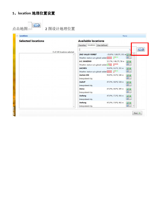
1、location 地理位置设置
点击地图
2 图设计地理位置
在
创建需要的地理位置
位置类型 天气界定
全球辐射 设计参考去
用户定义位置 批处理模式
放大 缩小 创建新的位置
点击
进入下表,创建新的地理位置
经纬 情况
输入经纬度确定地理位置,点击 save ,然后 退出,返回 location 菜单,在 user defined 选 择新添加的城市
每天全球辐射 每天温度 数据表 辐射 温度 降水量 日照时间
diffuse radiation global radiation sunshine duration astronomical sunshine duration
散射辐射 全球辐射 日照时间 天文日照时间
大气质量
内插
最近的 aeronet 站 自定义
数据 数据库
辐照值 未来 温度值
ipcc 的场景以后各期
高级设置
高级设计待研究 3、Format 设置
点击 NEXT 进入
输出格式建Leabharlann 模拟太阳能热一般使用
自定义
一般选着 PV 中 的 PV Syst 格式 (只能选一个)
4、output(输出)
- 1、下载文档前请自行甄别文档内容的完整性,平台不提供额外的编辑、内容补充、找答案等附加服务。
- 2、"仅部分预览"的文档,不可在线预览部分如存在完整性等问题,可反馈申请退款(可完整预览的文档不适用该条件!)。
- 3、如文档侵犯您的权益,请联系客服反馈,我们会尽快为您处理(人工客服工作时间:9:00-18:30)。
主题:meteonorm中文使用手册
1. 介绍
meteonorm是一款专业的气象数据软件,为工程师、研究人员和学生提供了全球气象数据的准确性和可靠性。
它集成了全球范围内的气
象数据,包括太阳辐射、温度、湿度、风速等多种气象参数,并提供
了丰富的数据处理和分析功能。
在本文中,我们将深入探讨meteonorm的中文使用手册,帮助您更好地理解和使用这款软件。
2. 了解软件功能
我们要了解meteonorm软件的基本功能和数据内容。
meteonorm 不仅提供了世界各地的气象数据,还包括了不同时间段的数据,如历史、现在和未来的气象数据。
这使得meteonorm成为了研究太阳能、风能等可再生能源资源的重要工具。
3. 数据导入和处理
在使用meteonorm时,我们需要学会如何导入和处理气象数据。
软件提供了多种导入数据的方式,如通过CSV文件、气象站数据或手动输入等。
meteonorm还支持对数据进行校准和处理,确保数据的
准确性和可靠性。
4. 数据分析和应用
一旦我们获得了所需的气象数据,就可以进行数据分析和应用。
meteonorm提供了丰富的分析工具,如太阳能辐射的分析、气象条
件的频率分布分析等,帮助用户更好地理解气象数据并应用于实际工
程和研究中。
5. 个人观点和实践
在实际使用中,我发现meteonorm的确是一款非常强大的气象数
据软件,它的全球数据覆盖范围广,数据的准确性和可靠性也得到了
许多用户的认可。
meteonorm还在不断更新和完善,为用户提供更
好的使用体验和数据支持。
6. 总结
通过本次对meteonorm中文使用手册的深入探讨,我们对这款软
件的功能和使用方法有了更加全面和深入的了解。
只有不断学习和实践,才能更好地掌握这款强大的气象数据工具,为我们的工程和研究
带来更多的帮助。
通过这篇文章,你将对meteonorm中文使用手册有了更全面和深入
的了解,可以更好地应用于实际工程和研究中。
希望这篇文章能帮助
到你,也希望你能更好地掌握和应用meteonorm这一强大的气象数
据软件。
Metronorm的中文使用手册可以帮助用户更好地掌握这款专业的气象数据软件。
在实际工程和研究中,利用metronorm可以方
便地获取全球范围内的气象数据,包括太阳辐射、温度、湿度、风速
等多种气象参数,从而为可再生能源资源的研究和利用提供重要支持。
随着气候变化和可再生能源的需求不断增加,使用可靠的气象数据软
件至关重要。
metronorm的功能和数据内容非常丰富,用户可以根据自己的需求选择不同时间段的气象数据,包括历史、现在和未来的数据。
这为用户提供了更多的选择和灵活性。
在使用metronorm时,数据的导入和处理是关键步骤。
软件提供了
多种导入数据的方式,用户可以选择适合自己的方式导入气象数据,
如通过CSV文件、气象站数据或手动输入等。
metronorm还支持数
据的校准和处理,确保数据的准确性和可靠性。
一旦获取了所需的气象数据,metronorm还提供了丰富的数据分析工具,如太阳能辐射的分析、气象条件的频率分布分析等。
这些工具可
以帮助用户更好地理解气象数据,并将其应用于实际工程和研究中。
在实际使用中,许多用户都对metronorm的全球数据覆盖范围广和
数据的准确性和可靠性给予了肯定。
metronorm还在不断更新和完善,为用户提供更好的使用体验和数据支持。
通过对metronorm中文使用手册的深入了解,用户可以更好地掌握
这款强大的气象数据工具,为实际工程和研究带来更多的帮助。
只有
不断学习和实践,才能更好地利用metronorm,为气象数据分析和可再生能源的研究和利用提供关键支持。
metronorm的中文使用手册为用户提供了全面和深入的了解,帮助他们更好地应用于实际工程和研究中。
希望本文能帮助更多的用户更好地掌握和应用metronorm这一强大的气象数据软件,为可再生能源的发展贡献力量。