旋塞阀说明书英文Plug valve
FMC旋塞阀技术资料
Operating & Maintenance ManualWeco® Model ULT Plug ValvesOPERATING AND MAINTENANCE MANUAL, WECO MODEL ULTPLUG VALVESRev ECN No. Date Reviewed By Approved By StatusA 5014824 16-DEC-2005Douglas, Don Soltau, James RELEASEDSummary:Operating, maintenance and storage instructions – WECO® Model ULT Plug ValvesTable of ContentsSection Title Page1.0SAFETY INSTRUCTIONS (5)2.0OPERATING INSTRUCTIONS (5)3.0MAINTENANCE INSTRUCTIONS (6)3.1REQUIRED TOOLS (7)3.2DISASSEMBLY (7)3.3ASSEMBLY (8)3.4KITS AVAILABLE (9)4.0STORAGE INSTRUCTIONS (9)5.0APPENDIX – Assembly/Disassembly Graphics (10)6.0TROUBLE SHOOTING GUIDE (15)List of FiguresFigures Page Figure 1: Plug Valve Assembly* (6)Figure 2: Install/Remove the Body Cap (10)Figure 3: Remove the Plug (10)Figure 4: Install/Remove the Side Segments (11)Figure 5: Install/Remove the Seal Segments (11)Figure 6: Install/Remove the Wave Springs (12)Figure 7: Seal Segment Inspection (12)Figure 8: Position of Stem (13)Figure 9: Align Milled Slot of Plug with Dimples (13)Figure 10: Install Wave Springs (14)WARNINGSFMC cannot anticipate all of the situations a user may encounter while installing andusing FMC products. Therefore, the user of FMC products MUST know and follow allapplicable industry specifications on the safe installation and use of these products.Refer to the FMC product catalogues, product brochures and installation, operatingand maintenance manuals for additional product safety information or contact FMC at800-772-8582.1. Do not mix or assemble components, parts or endconnections with different pressure ratings. Mismatchedparts may fail under pressure.2. Do not use or substitute non-FMC components or parts inFMC products and assemblies.3. Do not strike, tighten or loosen pressurized components orconnections.4. Do not exceed the rated working pressure or temperaturerating of the product.5. Complete and proper make-up of components andconnections is required to attain rated working pressure.6. Do not use severely worn, eroded or corroded products.Contact FMC for more information on how to identify thelimits of erosion and corrosion.7. Follow safe practices when using products in overheadapplications. Products not properly secured could fall.8. Select only appropriate product and materials for theintended service:9. Do not expose standard service products to sour gas fluids.(Refer to NACE MR0175). Do not interchange sour gaswith standard service components.10. Use appropriate safety precautions when working withferrous products in below freezing temperatures. Freezingtemperatures lower the impact strength of ferrous materials.11. Follow manufacturers instructions and Material Safety DataSheet directions when using solvents12. Make certain that personnel and facilities are protectedfrom residual hazardous fluids before disassembly of anyproduct.13. If any leakage is detected from FMC products, removethem from service immediately to prevent potential damageand personal injury.1.0 SAFETY INSTRUCTIONSThe applications of FMC products are in working environments where generalpersonnel safety procedures and policies MUST be followed. Always use appropriateprotective equipment in high pressure, extreme temperature or severe serviceapplications.2.0 OPERATING INSTRUCTIONSWECO® Model ULT plug valves are primarily used as isolation valves. The ULT plugvalve is bi-directional; it can isolate flow from either direction.1. Prior to use, the valve should be inspected for properoperation. The valve should be free of contamination andthe valve should actuate from open to close position freely.2. The valve should be thoroughly flushed with clean freshwater after each use and the bore of the valve should besprayed with a light oil or comparable corrosion inhibitor.3. While the valve is in the open position, use the greaseinserts located on both sides of the valve to pump CLIMAXplug valve grease into the valve until the grease is flushedout into the bore of the valve.4. To prevent leakage, malfunctions resulting from internalwear or seal degradation, the user must establish apreventative maintenance and inspection program. Thisprogram must include:1. Inspection of parts to detect loss of wall thickness thatmay result in decreased pressure capacity.2. Routine replacement of seals and inspection for properoperation.3.0 MAINTENANCE INSTRUCTIONSFigure 1: Plug Valve Assembly** Note: Side segments, wave springs and grease plugs are not visible in this view.3.1 REQUIRED TOOLSSpanner wrench, sledge hammer, screw driver, adjustable wrench, solvent/rags,rubber mallet, grease, grease gun, Climax No. 1500, Anti-seize or equivalent, 400 gritor finer 3M WETORDRY Tri-M-Ite paper, and personal safety equipment. For the 4”ULT plug valve an optional FMC plug installation tool can be used.3.2 DISASSEMBLY1. Before getting started, bleed all pressure from the line.may cause equipment damage and/or severe injury to operatingpersonnel.2. If the bottom of the valve is not accessible, you will have to remove the valve fromthe line. You will need at least 2X the height of the valve as clearance on thebottom to service.3. Prior to assembly, cycle the valve to open to release any fluids that may beretained in the body. Leave the valve in the full open position.4. Remove the grease fittings using the adjustable wrench.5. If the valve is removed from the line, place the assembly on one side on a securesurface. Attach the spanner wrench to the body cap (see figure 2). Using thesledgehammer to drive the spanner wrench, loosen the body cap from the valvebody taking special care not to damage the threads and o-ring seal groove.6. Place the valve assembly with the valve cavity facing up (see figure 3). Using abar-type puller, remove the plug utilizing the tapped hole on the bottom of plugwhile reacting against the valve body. Pull the plug out of the valve cavity takingcare not to damage the plug as this is a metal-to-metal sealing surface. Anoptional FMC plug removal tool can be used (4” valve only).7. Remove the side segments (see Figure 4) and then the seal segments (seeFigure 5). If necessary, carefully pry the side segments away from the body usinga screwdriver (Be careful not to scratch the valve cavity).8. Remove the booster springs from each seal segments (see figure 6).Note: Do not remove the plug by pushing on the stem. If the stem isremoved, a separate procedure is required to re-install the stem andstem seals to prevent leakage.9. Remove and properly discard the old grease on the parts and inside the valvecavity.3.3 ASSEMBLY1. Check/verify parts against bill of materials; clean all parts and inspect for nicks,burrs or excessive wear.2. If the work is being performed with the valve out of line, position the body so thatthe assembly can be performed with the valve cavity facing upward. Preferably,the valve is to be placed on a table modified to allow the passage of the stemthrough the table top.3. Install the inner and outer s-seals onto the seal segments. Make sure thatorientation is correct (after installation a single “o-ring bump” should face outwardin each s-seal). Apply a thin film of Lubriplate to the outside diameter surfaces ofthe seal segments. Using your index finger remove the excess Lubriplatebetween the two s-seals. If too much Lubriplate is in between the s-seals,difficulty in the installation of the plug could occur later. Apply a liberal amount ofplug valve grease to the ID of the seal segments. Insure that the ramp angle iscovered. Carefully install the two seal segments into the valve cavity whilealigning the locator pin holes with the locator pins in the valve cavity (see Figure5).4. Inspect the lead-in chamfer of the seal segments; this area should be free ofnicks, chips and sharp edges (see figure 7). Apply a liberal amount of Lubriplateto the lead-in chamfer of the seal segments.5. Apply a liberal amount of plug valve grease to the side segments and install theminto the valve cavity. It may be necessary to push the seals segments outwardwhen installing the side segments (see figure 4).6. Check plug for nicks, scratches and sharp edges on the lead-in chamfer. Apply aliberal amount of grease to the OD of the plug and Lubriplate to the lead-inchamfer. Verify the stem is in the open position (The position of the tang of thestem should be perpendicular (vertical) to the fluid bore of the valve; see figure 8).Align the milled slot of the plug with the dimples of the seal segments (see figure9). Using an arbor press gently press the plug in. Verify that the plug has seatedcorrectly by looking in the bore; the bore of the plug should be inline with the boreof the body. An optional FMC plug installation tool can be used (4” valve only).7. Drive all four booster springs in the slots formed by the outer diameter of the sealsegments and the valve cavity using a hammer and a brass punch (see figure10). It is important that the brass punch is used in driving the last inch of thebooster springs into the assembly to prevent scoring the valve cavity sealing area.8. Install the back-up rings and o-rings onto the body cap. Verify that the orientationis correct using the assembly drawing in figure 1. Apply anti-seize to the threadsof the body cap and Lubriplate to the seals. Install the body cap on the assembly(see figure 2).3.4 KITS AVAILABLEThere are two types of kits available for servicing the WECO® Model ULT Plug Valve.• Repair Kit w/ Plug: This is the most commonly needed kit and consists of the parts recommended for rebuilding the valve. This kit includes the plug.• Repair Kit w/o Plug: This is the most commonly needed kit and consists of the parts recommended for rebuilding the valve. This kit includes the plug.Table 1: WECO® Model ULT Plug Valve Kits – Standard Service & Sour Service3” ULT100 3” ULT150 3-1/16”ULT1503” ULT200 4” ULT100 4” ULT1504-1/16”ULT150StandardKit w/ PlugN/a 3265500 P528304 P519446 P518243 3268180 P531289 StandardKit w/oPlugN/a P510214 n/a n/a P519505 n/a n/aSour GasKit3266024 n/a n/a P525393 n/a n/a n/a4.0 STORAGE INSTRUCTIONSWhen not in use, the valve should be stored in an area that protects it from sun, rain,sand, and other debris. Before storing the valve, ensure that the operating fluidshave been removed by flushing with water. After cleaning, fully drain all fluids fromthe valve and spray the valve with a water displacing lubricant such as a Teflon / oilmix. Spray inside both flow bores as far into the valve as possible. Also spray thethreads of the union ends. With the valve in the open position, use the grease insertsto grease the valve until the grease is flushed out into the bore of the valve. Duringlong-term storage keep the valve dry and painted to prevent corrosion.5.0 APPENDIX – Assembly/Disassembly GraphicsFigure 2: Install/Remove the Body CapFigure 3: Remove the PlugFigure 4: Install/Remove the Side SegmentsFigure 5: Install/Remove the Seal SegmentsFigure 6: Install/Remove the Wave SpringsFigure 7: Seal Segment InspectionFigure 8: Position of StemFigure 9: Align Milled Slot of Plug with DimplesFigure 10: Install Wave Springs6.0 TROUBLE SHOOTING GUIDEFigure 11. Leak path diagramProblem Possible Cause Recommended RepairDamage body cap o-ring. Incorrect installation of backup ring Remove body cap. Replace body cap o-ring and backup ring. Verify the backup ring is installed with concave side toward the o-ring. The o-ring should be located in the groove furthest from the threads. Fully grease and pressure test the valve to full working pressure prior to returning to service.Leak at body cap. Figure 11, leak path “A”. Dents and deep scratches in thebody cavity or body cap seal area.Disassemble valve. Inspect body cavity for scratches,dents or corrosion in the body cap sealing area.Repair minor scratches and corrosion with 400 gritWETORDRY. Deep dents or gouges may require thebody to be replaced. Fully grease and pressure testthe valve to full working pressure prior to returning toservice.Problem Possible CauseRecommended RepairContamination or foreign debrisbetween the seal segment and body. Cycle opened and closed several valve times. Fully grease valve and cycle several more times.Damaged or aged seal segment face seal.Dissemble valve. Replace seal segment face seal. Full grease and pressure test the valve to full working pressure prior to returning to service.Damaged seal segment seal area due to scratches, corrosion, or erosion. Disassemble valve. Inspect seal segments for scratches, dents or corrosion in the body cap sealing area. Repair minor scratches and corrosion with 400grit WETORDRY. Deep dents or gouges may require the seal segments to be replaced. Fully grease and pressure test the valve to full working pressure prior to returning to service.Leaking between seal segment and body. Figure 11, leak path “B”.Damaged body seal segment sealing surface due to scratches, corrosion, or erosion. Disassemble valve. Inspect body to seal segment for scratches, dents or corrosion in the body cap sealing area. Repair minor scratches and corrosion with 400grit WETORDRY. Deep dents or gouges may require the body to be replaced. Fully grease and pressure test the valve to full working pressure prior to returning to service.Contamination or foreign debris between the seal segment and plug. Cycle opened and closed several valve times. Fully grease valve and cycle several more times. Damaged seal segment due to scratched, corrosion or erosion. Disassemble valve. Inspect seal segments for scratches, dents or corrosion in the body cap sealingarea. Repair minor scratches and corrosion with 400 grit WETORDRY. Deep dents or gouges may require the seal segments to be replaced. Fully grease and pressure test the valve to full working pressure prior to returning to service.Leak between seal segment and plug. Figure 11, leak path “C”Damaged plug sealing surface due to scratches, corrosion, erosion, chipped or damaged plating. Disassemble valve. Inspect plug for scratches, dents or corrosion in the sealing area. Repair minor scratches and corrosion with 400 grit WETORDRY.Deep dents or gouges may require the plug to be replaced. Fully grease and pressure test the valve to full working pressure prior to returning to service.ProblemPossible CauseRecommended RepairHydraulic oil from the hydraulic operator (if applicable).Check hydraulic inlet and outlet fitting for leaks.Remove operator/actuator and test for leaks. Replace actuator if leakage is found. Fully grease and pressure test the valve to full working pressure prior to returning to service.Damaged stem or stem adapter o-rings or back-ups.Disassemble operator/actuator. Disassemble valve. Inspect the stem and stem adapter o-rings and back-ups for damage. Replace any damages o-ring and back-ups. Fully grease and pressure test the valve to full working pressure prior to returning to service. Damaged or contaminated stem to stem adapter seal surfaces.Disassemble operator/actuator. Disassemble valve. Inspect the stem to stem adapter for scratches, dents or corrosion. Repair minor scratches and corrosion with 400 grit WETORDRY. Deep dents or gouges may require the stem or stem adapter to be replaced. Fully grease and pressure test the valve to full working pressure prior to returning to service.Leak between valve body andoperator/actuator. Figure 11, leak path “D”Damaged or contaminated body to stem adapter seal surfaces.Disassemble operator/actuator. Disassemble valve. Inspect the stem adapter seal area for scratches, dents or corrosion. Repair minor scratches and corrosion with 400 grit WETORDRY. Deep dents or gouges may require the body to be replaced. Fully grease and pressure test the valve to full working pressure prior to returning to service.Problem Possible Cause Recommended RepairLoose grease fitting. Tighten the grease fitting. Fully grease and pressuretest the valve to full working pressure prior toreturning to service.Damaged or contaminated grease fitting. Remove grease fitting and replace with a new grease fitting using Teflon tape on threads. Fully grease and pressure test the valve to full working pressure prior to returning to service.Damaged or contaminated grease fitting threads. Remove grease fitting. Clean and inspect the threads. If the threads are intact , replace the Teflon tape on the grease fittings and install in the body. If the threads are damaged, replace the grease fitting with a new grease fitting using Teflon tape on the threads. Fully grease and pressure test the valve to full working pressure prior to returning to service.Leak at grease fitting. Figure 11, leak path “E”.Damaged body grease fitting threads. Remove the grease fitting. Clean and inspect body threads. If the threads are intact, replace the Teflon tape on the grease fitting and install in the body. If threads are damaged replace the body. Fully grease and pressure test the valve to full working pressure prior to returning to service.FMC Technologies, Inc 180377067Manufacturing282576401 Aberdeen, Scotland Dubai, United Arab Emirates Las Morochas, Venezuela Macae, RJ, Brazil SingaporeOklahoma City, Oklahoma Rock Springs, Wyoming North TexasTel940.328.0800Fax940.328.0803 Alice, TexasTel361.668.0886Fax361.668.0905 Farmington, New Mexico Tel505.327.0634Fax505.327.0641 Grand Junction, Colorado Tel970.245.1553Fax970.245.6066 Lafayette, LouisianaTel337.837.0700Fax337.839.2235 Longview, TexasTel903.757.4180Fax903.757.2514 Odessa, TexasTel432.552.9150Fax432.552.9151 Villahermosa, Mexico Tel(52) 993.310.4870 Fax(52) 993.350.1661。
旋塞
旋塞
plugcock;plug valve
又称栓塞。
俗称考克(cock)。
他动阀一种。
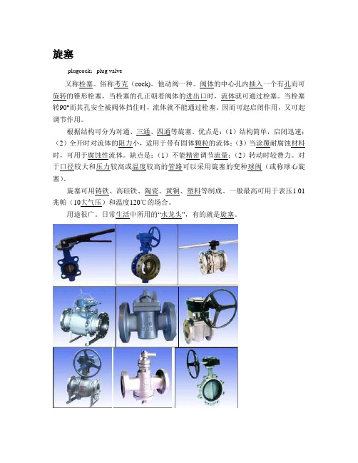
阀体的中心孔内插入一个有孔而可旋转的锥形栓塞,当栓塞的孔正朝着阀体的进出口时,流体就可通过栓塞。
当栓塞转90°而其孔安全被阀体挡住时,流体就不能通过栓塞。
因而可起启闭作用,又可起调节作用。
根据结构可分为对通、三通、四通等旋塞。
优点是:(1)结构简单,启闭迅速;(2)全开时对流体的阻力小,适用于带有固体颗粒的流体;(3)当涂覆耐腐蚀材料时,可用于腐蚀性流体。
缺点是:(1)不能精密调节流量;(2)转动时较费力。
对于口径较大和压力较高或温度较高的管路可以采用旋塞的变种球阀(或称球心旋塞)。
旋塞可用铸铁、高硅铁、陶瓷、黄铜、塑料等制成。
一般最高可用于表压1.01兆帕(10大气压)和温度120℃的场合。
用途很广。
日常生活中所用的“水龙头”,有的就是旋塞。
旋塞阀说明书

旋塞阀操作和维护手册一、用途和结构特点旋塞阀广泛地应用于油田开采、输送和精练设备中,同时也广泛用于石油化工、化工、煤气、天然气、液化石油气、暖通行业以及一般工业中手动旋塞阀二、技术参数及性能工作原理旋塞阀是关闭件或柱塞形的旋转阀,通过旋转90度使阀塞上的通道口与阀体上的通道口相同或分开,实现开启或关闭的一种阀门。
压力实验性能规范表主要零件材料三、安装、维护和使用说明(一)安装3.1.1 安装前应仔细核对阀门铭牌内容,保证阀门的类型、尺寸、阀座材料、使用温度等额定符合管道的使用情况。
3.1.2 安装使用前最好能对阀门所有连接处的螺栓进行检查,保证其以均匀拧紧。
并检查填料是否压紧、密封。
3.1.3 安装前应对管线进行清扫,去除管线中的油污、焊渣等杂质。
3.1.4 阀门在搬运中应轻取,禁止抛仍或跌落。
3.1.5大型阀门应安装固定支架,保证阀门安装后,整条管线的稳定性和安全性。
3.1.6阀门安装时,应取下阀门两端的防尘盖。
3.1.7阀门往管道上安装时,在法兰间垫进合适的密封垫片,取相应的规格的螺栓把法兰对角均匀拧紧。
3.1.8如阀门安装后发现阀杆密封有渗漏,可能是在运输中震动和温度变化引起填料松弛,拧紧填料压盖螺母即可。
可减轻操作力矩。
3.1.9如阀门为非手动装置,必须设置好执行机构的空间位置,以便在意外情况的人工操作及维修。
并在正式投产前对驱动装置进行检查和测试。
(二)储存与维护3.2.1在干燥通风的室内,两端应盖上防尘盖,以保证阀门的内腔清洁。
3.2.2大型阀门存放在室外保管时,应将其支撑起来,不要与地面接触,并用塑料薄腊覆盖保护。
3.2.3长期存放的阀门重新使用时,应检查调料是否失效,并对各转动部位加注润滑油。
3.2.4阀门在使用中应定期检查以保持阀门的使用性能,包括定期拧紧阀门填料压盖螺母,以补偿阀杆磨损。
如果阀门与驱动装置使用无松动联轴器,则要先松开联轴器,然后拧紧填料压盖螺母。
3.2.5阀门必须在规定的使用期内使用和进行维修,包括更换垫片、填料、密封圈及球体(按需要)等密封副。
旋塞阀说明书英文Plug valve
Plug valve operating instructions(X43F-150Lb-2)PREPARED BY:REVIEWED BY:APPROVED BY:2013.7.10XINTAI V ALVE CO., LTD.CATALOGUE1. Purpose and performance specifications (1)2. U sing standard (1)3.Structural characteristics and operation principle (2)4.Valve main parts material (3)5.Storage, installation, use, inspection (3)6. Troubles and troubleshooting (5)7. Matters needing atten tion (6)1、Purpose and performance specifications1.1 Usagea、This product is mainly used for pipeline gas, liquid and granular medium as an opening and closing device, connected or cut off the medium flow, not suitable for regulating media flow. With the flow resistance is small, open and close more effort etc.b、Scope of application: chemical, petroleum, metallurgy, papermaking, pharmaceutical and other industries.1.2 Performance specifications1.3The maximum working pressure rating of the valve (Pressure - temperature reference)Table temperature refers to the state line the medium temperature, pressure is continuous table without impact pressure1.4The valve flow coefficient: Kv=120m.1.5 The new valve open torque:320N.m.2 、Using standard2.1 Design and manufacture according to the provisions of API 6D version twenty-third;2.2 Inspection and testing in accordance with API 6D twenty-third Edition;2.3 Flange size according to the provisions of ASME B16.5:2003;2.4The length of the structure according to the provisions of API 6D version twenty-third;2.5 Valve pressure - temperature reference according to the ASME B16.34: 2004.3、Structural characteristics and operation principle3.1Structure and main dimensions refer to sketch1 The valve body2 Bushing3 Plug4 In the flange gasket5 The adjusting shim6 Packing7 Filler8 The six hexagon nuts9 Stud bolt 10 The valve cover 11 Filler plate 12 Inside the six socket head cap screw 13 wrench 14 The six hexagon head bolts 15 Big gasket 16 Stud bolt 17 The handle head3.2The plug valve is driven by rotating the wrench plug rotating 90 DEG C to open or close.3.3 The closed valve wrench clockwise rotation of 90 degrees.3.4 The valve using the valve lining PTFE material, good sealing performance, the use of temperature ≤ 150 ℃.3.5 The valve uses a wedge type plug, rotation torque is small, easy to seal, not easily stuck due to temperature change.3.6 The adjusting shim structure, auxiliary valve cover pressing plugs to seal, and easy to repair.3.7 The valve cover is provided with a V type of PTFE filler, lubricant oil installation fashion into a little, good sealing performance.3.8 The quenching and tempering, chrome plating, enhance hardness, improve sealing performance and service life.4、Valve main parts material5、Storage, Installation, Using, Maintenance5.1 Storagea. Valves must be stored in a dry and ventilative room.b.During the period of storage, The disc should be always be shut and fixed and the inletand outlet should be blocked.c.During the period of storage, the outside portion of the stem and the machined surfaceshould be covered by an easily cleaned antirust.d The valve stored for a long time should be inspected and cleaned at an expected time. At the same time, the antirust should be re-brushed.5.2 Installationa. The valve can be installed freely, Usual used in horizontal pipe line ,and can also used invertical or bevel pipe line, but it should be convenient to maintenance, inspection and operation.b.Before installation, operators must review whether the contents on the marking andnameplate conform with the practical requirements.c.Before installation, operators must inspect the inside , remove the disc fix set ,and try toturn on the disc to check the seal face ,and clear it.d.Installation this valve , must be note the flow way of the medium , and must keep sameway of the medium and the arrowhead ,otherwise can stop the natural way of medium. 5.3 Usinga. The practical condition intending to use valves must conform with the requirements specified on nameplate and in the operation instruction.b.The valve only works for getting or shutting off medium. Mustn’t take it as theregulation valve.c. When shutting the valve ,it will have water hammer in the pipe line , badly will damaged the valve , so the user should inspect on time , if find some problem repair in time .5.4 Inspection1. During the period of using valves, The following projects must be inspected at an expected time. Once any noncompliance is found, Please correct it right now.a.Whether fasteners become less crowded or notb.Whether packing is worn out and gaskets are mangled or not. (inspection without work)c. Whether the disc can turn on easily ,and whether have the problem of obstruct.d. Whether the wall thickness of valves becomes thin distinctly for corrosion or erosion or not. If the wall thickness is less than the net valuation only satisfying the requirements of tensile strength or there exists a visually leakage, the valve must be scraped.e. After valves are inspected and assembled, they are tested per responsible specifications and the records must be documented to refer to later.6 Faults and Elimination7 Note:7.1 The valve material selection and the possibility of deterioration in use and necessary periodic inspection by the user is responsible for considering7.2 The valve design only consider the general case, if there are special requirements shall be specified in the contract.7.3 The valve design only consider certain corrosion, there is a serious or special corrosion occasion, the valve does not apply.7.4 The valve operating temperature range shall not exceed the provisions of article 1.2 in the table, more than (including instantaneous) the range of consequences is the user's responsibility.7.5 The corresponding temperature valve the maximum working pressure shall not exceed the provisions of article 1.3 in the table, more than (including instantaneous) pressure rated the scope or use and temperature are not corresponding to the value of the consequences is completely user Responsibility.7.6 The valve is used in the media are listed in article 1.2 in the table, cause beyond the scope of the consequences is entirely the responsibility of the user.7.7 Valve must not be pressure increase or replace the packing, sealing structure is not asusers replace with pressure filler reason.7.8 Valve operation process not welding repair and exterior paint.7.9 The valve shall be removed under compression.7.10 Valve according to the fourth sheet material matching under repair.7.11 The valve design is not life calculation, test and fatigue strength calculation, users must be regular maintenance, replacement in use.7.12 The valve design not consider seismic load, the consequences arising therefrom, shall not be responsible for manufacturing factory.。
Plug Valve(旋塞阀)
海外技术合作支援业务的TechnologySales Kit技术名称:Plug Valve(Oil Field用高压Valve)企业名称:山东金属工业(株)公司名称一.出口范围及合作形式1.技术名称Plug Valve:Oil Field用高压Valve2.技术的简介是当前全球油田地区原油输送管的必需品高压Plug Valve,由本公司独立研究开发,质量及价格竞争力优于国外生产的同类Vable。
3.技术适用领域、应用范围及用途Oil Field用高压Valve二.企业介绍1.代表董事Bae Sun-Bong2.企业的简介三.技术概要及特征1.技术概要及技术的必要性1)技术概要旋塞阀是关闭件成柱塞形的旋转阀,通过旋转90o使阀塞上的通道口与阀体上的通道口相通或切断,实现开启或关闭的一种阀门。
该类阀门的流阻比截止阀、蝶阀、柱塞阀小得多,只比全通径球阀略大,阀塞的形状可制成圆柱形或圆锥形。
2.技术特征、优点及竞争力1)在海外Oil Field用高压Plug Valve市场具有质量和价格竞争力优势。
2)采用本公司独立设计及技术开发的产品,具有质量及价格竞争力优势。
四.进入中国市场的必要信息1.知识产权情况经对中国有效专利的检索,以“高压旋塞阀”为主题词进行检索共发现5项实用新型专利。
涉及连接方式、闸板形状、密封方式、省力等。
由于山东金属工业(株)未能提供任何有关该高压旋塞阀的技术描述性的信息,故进行知识产权方面的比较是极为困难的。
可以肯定的是:以“高压旋塞阀”为主题词没有发现涉及发明专利。
2.相应技术的中国市场性售额规模阀门在机械产品中所占比重较大,据国外工业发达国家统计,阀门的产值超过压缩机、风机和水泵三者产值的总和,约占整个机械工业产值的5%。
中国的阀门产值只占压缩机、风机和水泵产值的一半,约占整个机械工业产值的1%左右。
阀门的用户行业较广,可分为石油、石化、化工、电力、水利、冶金、城建、机械、煤炭、食品和其他。
阀门部件英文对照表

阀门部件英文对照表Valve Components English Translation TableValves play a crucial role in regulating the flow of fluids in various industries. To ensure accurate communication and understanding between different professionals involved in valve manufacturing, installation, and maintenance, it is essential to have a standardized English translation table for valve components. This table provides an overview of commonly used valve parts and their English translations, enhancing clarity and efficiency in the industry.1. Valve Body –阀体(fá tǐ)The main housing of the valve that typically forms the primary structure. It provides the connection points for other valve components.2. Bonnet –顶盖(dǐng gài)The cover that encloses the valve stem and other internal parts of the valve. It ensures proper sealing and protection of the valve internals.3. Valve Trim –阀门修整件(fá mén xiū zhěng jiàn)The collective term for various components that directly contact the flowing fluid. It usually includes the seat, disc, stem, and other flow-control elements.4. Valve Seat –阀座 (fá zuò)The sealing surface located within the valve body, which provides a tight shut-off when in contact with the valve disc. It prevents fluid leakage when the valve is closed.5. Disc or Closure Member –阀瓣 (fá bàn)The moveable component that controls the flow of fluid through the valve. It can be a disc, ball, or other designs depending on the valve type.6. Stem –阀杆(fá gān)A rod-like component that connects the valve disc to the actuator. It transmits the motion from the actuator to the valve disc, regulating the flow of fluid.7. Actuator –作动器 (zuò dòng qì)The mechanical device responsible for operating and controlling the valve. It can be manually operated or powered by electricity, pneumatic or hydraulic pressure.8. Packing –压紧装置(yā jǐn zhuāng zhì)A component used to provide a seal around the valve stem, preventing leakage. Common types of packing include braided gland packing and mechanical seals.9. Gasket –垫片 (diàn piàn)A thin material placed between two components to create a seal, preventing leakage. Gaskets are commonly made of materials such as rubber, graphite, or metal.10. Bolts and Nuts –螺栓和螺母(luó shuān hé luó mǔ)Fasteners used to secure valve components together. Bolts are the threaded rods, and nuts are used to tighten them securely.11. Flange –法兰(fǎ lán)A disc-shaped component with bolt holes that connect two separate sections of a piping system together. Flanges allow easy assembly and disassembly of valves and pipes.12. Stem Nut –杆母(gǎn mǔ)A component that connects to the valve stem and allows manual operation of the valve by rotating the stem nut.13. Handwheel –手轮(shǒu lún)A manually operated device attached to the valve stem or actuator to provide manual control over valve operation. It is commonly used in situations where manual manipulation is required.14. Body Gasket –法兰垫片(fǎ lán diàn piàn)A sealing gasket placed between flanged connections to ensure a tight seal and prevent fluid leakage.15. Ball Valve –球阀 (qiú fá)A valve with a spherical disc that controls the flow by rotating it within the valve body. It offers quick shut-off and minimal flow restriction when fully open.16. Gate Valve –闸阀 (zhá fá)A valve with a gate-like disc that moves vertically to control the flow. It provides a tight seal when closed but has higher flow resistance compared to ball valves.17. Globe Valve –截止阀(jié zhǐ fá)A valve with a disc that moves up and down to regulate the flow. It offers precise control and is commonly used in applications requiring throttling or continuous flow adjustment.18. Check Valve –截止阀(jié zhǐ fá)A valve that allows fluid flow in one direction only, preventing backflow. It automatically closes when the flow reverses, ensuring check and preventing fluid reversal.19. Butterfly Valve –蝶阀 (dié fá)A valve with a disc (resembling a butterfly's wings) that rotates in the flow path to control fluid flow. It offers quick operation and low pressure drop.20. Plug Valve –塞阀(sāi fá)A valve with a cylindrical or tapered plug-shaped disc that rotates to control the flow. It provides reliable sealing but has higher flow resistance compared to other valve types.This English translation table for valve components aims to facilitate effective communication between professionals in the valve industry,ensuring accurate understanding and improved efficiency in valve-related projects. By using standard terminology, the industry can minimize errors and promote seamless collaboration among global stakeholders.。
3Z株式会社 油封式旋塞阀操作手册(英文版)

INSTALLATION, OPERATION AND IN-LINE MAINTENANCE MANUAL
DOC.NO. 3Z-QM-235 ISSUED
3/15
OCT., 09, 2005
0. PREFACE.
A plug valve should be managed properly in the each stage of transportation, installation, operation, and maintenance. Also, it depends on the managing status of a supervisor and a operator that the plug valve might raise high efficiency or not.
2. INSTALLATION
A. Preparation for installation A plug valve being carried, a rope, wire, and shackle should be strong enough to sustain the total weight. A plug valve should be installed with the firm pipe line. Move the valves as close as possible to the installation site before removing packing and end protectors. After removing packaging, clean end connections to remove any unwanted paint or rust inhibitor. Ensure that the valve is fully open. Inspect the internal bore of the valve. If there is excess sealant visible around the plug ports, this should be scraped out. If the valve has been in storage for over 12 months we recommend that additional valve sealant be injected prior to operation.
各种阀门中英文对照
各种阀门中英文对照
哇塞,让我们来瞧瞧各种阀门的中英文对照呀!
Gate valve - 闸阀,这就像是通道的守卫者,在需要截断或开启流体通道的时候就派上用场啦,比如在管道输送系统中。
Globe valve - 截止阀,就如同精准的调控开关,用来精确控制流体流量呢,像在一些要求精细调节的工业流程里就会用到。
Check valve - 止回阀,它就像个忠诚的卫士,防止流体倒流呀,比如在供水系统中可重要啦。
Ball valve - 球阀,操作起来轻松快捷,就像个灵活的小助手,常用于需要快速启闭的场合,像家庭的水管系统。
Butterfly valve - 蝶阀,如同翩翩起舞的蝴蝶般优雅,在大口径管道中常常能看到它的身影呢。
Diaphragm valve - 隔膜阀,好似一层保护膜,能有效控制腐蚀性流体,在化工领域很常见哟。
Plug valve - 旋塞阀,就像是个小巧的开关,简单而实用,在一些小型设备中能发挥作用。
Relief valve - 安全阀,那可是安全的保障呀,在压力过高时能及时释放,像在锅炉等设备上。
Needle valve - 针阀,像根精细的针一样,能精确调节微小流量,在实验室等地方很有用呢。
Control valve - 调节阀,是个智能的调控大师,能精确调节流体的参数,在自动化控制系统中可少不了它。
哎呀呀,这些阀门的中英文对照是不是很有意思呀!在我们的生活和工业中,它们可都扮演着重要的角色呢!
个人观点:阀门虽然看起来小小的,但它们的作用可真是大大的呀!不同的阀门有着不同的特点和用途,就像我们每个人都有自己独特的价值一样。
它们在各种领域默默奉献,保障着系统的正常运行,真的是很了不起呢!。
- 1、下载文档前请自行甄别文档内容的完整性,平台不提供额外的编辑、内容补充、找答案等附加服务。
- 2、"仅部分预览"的文档,不可在线预览部分如存在完整性等问题,可反馈申请退款(可完整预览的文档不适用该条件!)。
- 3、如文档侵犯您的权益,请联系客服反馈,我们会尽快为您处理(人工客服工作时间:9:00-18:30)。
Plug valve operating instructions(X43F-150Lb-2)PREPARED BY:REVIEWED BY:APPROVED BY:2013.7.10XINTAI V ALVE CO., LTD.CATALOGUE1. Purpose and performance specifications (1)2. U sing standard (1)3.Structural characteristics and operation principle (2)4.Valve main parts material (3)5.Storage, installation, use, inspection (3)6. Troubles and troubleshooting (5)7. Matters needing atten tion (6)1、Purpose and performance specifications1.1 Usagea、This product is mainly used for pipeline gas, liquid and granular medium as an opening and closing device, connected or cut off the medium flow, not suitable for regulating media flow. With the flow resistance is small, open and close more effort etc.b、Scope of application: chemical, petroleum, metallurgy, papermaking, pharmaceutical and other industries.1.2 Performance specificationsNominal diameter(NPS) 2 inPressure rating(Class)150 LbTest pressure Shell test 3.0MPa seal test 2.2Low pressure sealtest0.6Suitable temperature -29~120 ºCApplicable medium Water, oil, non - corrosive gas or liquid1.3The maximum working pressure rating of the valve (Pressure - temperature reference)(Gauge pressure:MPa)Temperature(ºC) -29~38 50 100 150Ratings 1.96 1.92 1.77 1.58Table temperature refers to the state line the medium temperature, pressure is continuous table without impact pressure1.4The valve flow coefficient: Kv=120m.1.5 The new valve open torque:320N.m.2 、Using standard2.1 Design and manufacture according to the provisions of API 6D version twenty-third;2.2 Inspection and testing in accordance with API 6D twenty-third Edition;2.3 Flange size according to the provisions of ASME B16.5:2003;2.4The length of the structure according to the provisions of API 6D version twenty-third;2.5 Valve pressure - temperature reference according to the ASME B16.34: 2004.3、Structural characteristics and operation principle3.1Structure and main dimensions refer to sketch1 The valve body2 Bushing3 Plug4 In the flange gasket5 The adjusting shim6 Packing7 Filler8 The six hexagon nuts9 Stud bolt 10 The valve cover 11 Filler plate 12 Inside the six socket head cap screw 13 wrench 14 The six hexagon head bolts 15 Big gasket 16 Stud bolt 17 The handle head3.2The plug valve is driven by rotating the wrench plug rotating 90 DEG C to open or close.3.3 The closed valve wrench clockwise rotation of 90 degrees.3.4 The valve using the valve lining PTFE material, good sealing performance, the use of temperature ≤ 150 ℃.3.5 The valve uses a wedge type plug, rotation torque is small, easy to seal, not easily stuck due to temperature change.3.6 The adjusting shim structure, auxiliary valve cover pressing plugs to seal, and easy to repair.3.7 The valve cover is provided with a V type of PTFE filler, lubricant oil installation fashion into a little, good sealing performance.3.8 The quenching and tempering, chrome plating, enhance hardness, improve sealing performance and service life.4、Valve main parts materialPart name The valvebody,valvecoverPlug FillerThepadStudboltThe sixhexagonnutsMaterials usedASTMA351 CF8ASTMA351 CF8PTFE PTFEASTMA193B8ASTMA194 85、Storage, Installation, Using, Maintenance5.1 Storagea. Valves must be stored in a dry and ventilative room.b.During the period of storage, The disc should be always be shut and fixed and the inletand outlet should be blocked.c.During the period of storage, the outside portion of the stem and the machined surfaceshould be covered by an easily cleaned antirust.d The valve stored for a long time should be inspected and cleaned at an expected time. At the same time, the antirust should be re-brushed.5.2 Installationa. The valve can be installed freely, Usual used in horizontal pipe line ,and can also used invertical or bevel pipe line, but it should be convenient to maintenance, inspection and operation.b.Before installation, operators must review whether the contents on the marking andnameplate conform with the practical requirements.c.Before installation, operators must inspect the inside , remove the disc fix set ,and try toturn on the disc to check the seal face ,and clear it.d.Installation this valve , must be note the flow way of the medium , and must keep sameway of the medium and the arrowhead ,otherwise can stop the natural way of medium. 5.3 Usinga. The practical condition intending to use valves must conform with the requirements specified on nameplate and in the operation instruction.b.The valve only works for getting or shutting off medium. Mustn’t take it as theregulation valve.c. When shutting the valve ,it will have water hammer in the pipe line , badly will damaged the valve , so the user should inspect on time , if find some problem repair in time .5.4 Inspection1. During the period of using valves, The following projects must be inspected at an expected time. Once any noncompliance is found, Please correct it right now.a.Whether fasteners become less crowded or notb.Whether packing is worn out and gaskets are mangled or not. (inspection without work)c. Whether the disc can turn on easily ,and whether have the problem of obstruct.d. Whether the wall thickness of valves becomes thin distinctly for corrosion or erosion or not. If the wall thickness is less than the net valuation only satisfying the requirements of tensile strength or there exists a visually leakage, the valve must be scraped.e. After valves are inspected and assembled, they are tested per responsible specifications and the records must be documented to refer to later.6 Faults and EliminationFaults Reasons Eliminating waysPacking leakage 1. The packing gland is not.2. Inadequate packing ring3. Packing damage failure1.Screw down the nut2.To increase the number ofturns3.Replacement of packingThe valve cover and valve body junction leakage 1.Bolt fastening unevenness2.Flange sealing surfacedamage3.Breakdown or failure ofgasket1.Tighten the bolts evenly2.To trim3.Replace the gasketThe sealing surface leakage 1.The sealing surfacecontaminants attached2.The sealing surface isdamaged3.Sealing surface oflong-term use of wear4.Seal leakage1.Remove dirt2.The new processing andfinishing3.The body back liningPTFE4. Flange nut to adjust shimdown, or tighten the packingpress nuts down, so that theplug down pressing linerseal.Bushing andvalve leakage Bushing and valve seal oil istoo smallReplace the bushingWrench rotation is not flexible or plug can not open and close 1.The packing too tight2.Packing gland device skew3.Stopper rod bending4.The sealing surfacecontaminants attachedUnscrew the nut properpacking glandAdjust the packing glandThe rod of correctionRemove dirt7 Note:7.1 The valve material selection and the possibility of deterioration in use and necessary periodic inspection by the user is responsible for considering7.2 The valve design only consider the general case, if there are special requirements shall be specified in the contract.7.3 The valve design only consider certain corrosion, there is a serious or special corrosion occasion, the valve does not apply.7.4 The valve operating temperature range shall not exceed the provisions of article 1.2 in the table, more than (including instantaneous) the range of consequences is the user's responsibility.7.5 The corresponding temperature valve the maximum working pressure shall not exceed the provisions of article 1.3 in the table, more than (including instantaneous) pressure rated the scope or use and temperature are not corresponding to the value of the consequences is completely user Responsibility.7.6 The valve is used in the media are listed in article 1.2 in the table, cause beyond the scope of the consequences is entirely the responsibility of the user.7.7 Valve must not be pressure increase or replace the packing, sealing structure is not asusers replace with pressure filler reason.7.8 Valve operation process not welding repair and exterior paint.7.9 The valve shall be removed under compression.7.10 Valve according to the fourth sheet material matching under repair.7.11 The valve design is not life calculation, test and fatigue strength calculation, users must be regular maintenance, replacement in use.7.12 The valve design not consider seismic load, the consequences arising therefrom, shall not be responsible for manufacturing factory.。