MGPM20-30Z资料下载
MAZ30620H资料
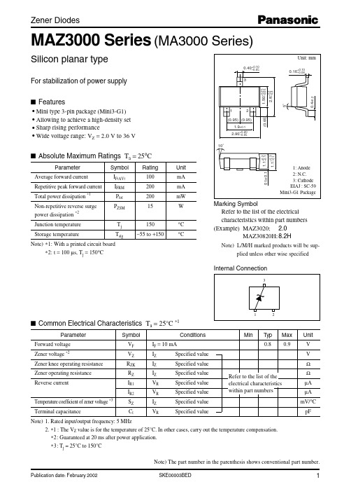
Symbol IF(AV) IFRM Ptot PZSM Tj Tstg
Rating 100 200 200 15 150 −55 to +150
Unit mA mA mW W °C °C
1.1+0.3 –0.1
s Absolute Maximum Ratings Ta = 25°C
1: Anode 2: N.C. 3: Cathode EIAJ : SC-59 Mini3-G1 Package
2
2
40 60
1
800 −2.7 −0.8 1.2 110
2
1
15 40
1
500 −2 1.2 2.5 95
4
4
5
5
5.3 5.3 3 5.5 5.7 5.9 5.9 2 6.1 6.3 6.5 6.5 1 6.7 7.0 7.2 7.2 0.5 7.5 7.7
60
6
20 0.5 300 0.4 2.3 3.7 90
60
6
15 0.5 140 1.2
3
4.5 85
60
6
15 0.5 120 2.5
4
5.3 80
60
6
15 0.5 120 3.2 4.6 6.2 75
Max 2.0 2.2 2.4 2.7L or 2.7H 2.7L 2.7H 3.0L or 3.0H 3.0L 3.0H 3.3L or 3.3H 3.3L 3.3H 3.6L or 3.6H 3.6L 3.6H 3.9L or 3.9H 3.9L 3.9H 4.3L or 4.3M or 4.3H 4.3L 4.3M 4.3H 4.7L or 4.7M or 4.7H 4.7L 180 4.7M 4.7H 5.1L or 5.1M or 5.1H 5.1L 160 5.1M 5.1H 5.6L or 5.6M or 5.6H 5.6L 140 5.6M 5.6H 6.2L or 6.2M or 6.2H 6.2L 130 6.2M 6.2H 6.8L or 6.8M or 6.8H 6.8L 110 6.8M 6.8H 7.5L or 7.5M or 7.5H 7.5L 100 7.5M 7.5H 8.2L or 8.2M or 8.2H 8.2L 95 8.2M 8.2H
淘汰式柔性耐用汽燃燃煤机用户指南说明书

CONTENTS PrefaceSafety InformationEngine SpecificationsSafety Label LocationAssemblingEngine UsageStart the EngineElectric Wiring DiagramRun the EngineStop the EnginePeriodicaI Check and MaintenanceLong-term StorageDetail DiagramAppendix 1.Overall and lnstallation Dimensions Appendix 2.Performance Curve & Sizes Of Pto Flanges Appendix 3.Sizes of PTO Flanges & Size of Output Shaft Appendix 4.Malfunction and remedy of diesel engine Limited WarrantyProduct Registration Card1 2 2 3 6 12 13 14 15 18 19 36 36 36 37 41 42Main ItemsTypeCombustion SystemBore x Stroke(mm)Piston Displacement(L)Rated PowerMax.kW(PS)Continue.kW(PS)Rated Speed(rpm)Rotation directionSpray Pressure kg/cm2(MPa)Applicable Fuel OilFuel Tank Capacity(L)Lubricating MethodApplicable Lube OilLube Oil Capacity Full(L)Effective(L)AHD186Single-cylinder,4-stroke,vertical,air-cooled,direct-injection diesel engineDirect injection combustion86 x 720.4189.08.53600Unclockwise viewed from the output shaft200(19.6)Light diesel5.5Pressure plus splashingSAE 10W30 beyond CC grade1.650.6Output ShaftFuel OilLubricating SystemStarting System Cooling System Recoil starter or Recoil/Electric starterForced air-cooledAMICO 3.ASSEMBLINGFUEL OIL CAPACITY ModelOil drain screw plug Dipstick air cleaner cover Wing nutelementfuel cock ("OPEN")regulator handlestarterhandlerecoil starterstarterhandlerecoil starterOpen the fuel cock.Put the engine speed leverin the "RUN" positionHold the starting handleloosely until you feelresistance Then return it slowly.Push the decompressionlever down and release Hold the starting handle firmly.Pull the rope hard and fast Pull it all the way e two hands if necessary.Pull the startinghandle slowly ......Start!If the engine doesn't starttry again from (1)23456For3, don't pull the ropetoo fast or hard.Always pull the rope slowly.For5,if you don't pull the ropeall the way out ,the engine won'tstart Always pull the rope all theway out.Always pull the rope hardand fast.For5,if you don't pull hard enough,the engine won't startSTART THE DIESEL ENGINEstandard panel installation panel of the cylinder head casehexagonal bolt M6 x 70removetwo boltslongwasherASSEMBLY:NO. Specification Quantity1 Electric starting switch body 12 Electric starting switch panel 13 Long washer 24 Hexagonal bolt M6 x 70 2PROCEDURES:Remove the electric starting switch body from thestandard panel, then reassemble it to the installa-tion panel of the cylinder head case.Screw off the two bolts from the cylinder head case.Clip the reassembled panel with the long washer,then tight it with hexagonal bolts.[OPERATING NOTICE]If the wire harness touch the muffleror the PTO shaft, the fire will result.Set the earth terminal of the harness with M6 bolt.1234groundterminalsM6 bolt couplerwire harness123ELECTRIC WIRING DIAGRAMblue redgeneratorblue blueredblue starting key of diesel engineyellowredregulatoryellowred black12Vstarting motoraccumulatorwhiteblackgray6.Run the EngineTo prevent the exhaust toxication, be sure to run the engine at ventilated place.To prevent personal injury, avoid hands, personal body and cloths from involving into the output shaft, pulley and V pulley etc moving parts.Check the moving parts and the surrounding parts after stop the engine. Be sure that there is no tool or cloth inside the engine body.The muffler is very hot during running or just after running, do not touch the muffler.The air cleaner will suck the surrounding airflow during the running. To prevent the injury, avoid hands, personal body and cloths approach this part.Warm up the engine for 5 minutes.If the engine is very hot, set the governor lever to the expected position.Be sure to regulate the engine speed with the governor lever.Do not screw off the adjusting bolt and the fuel adjusting bolts, otherwise the abnormal speed and output will result.If the engine continually exhaust black smoke dur-ing running, which indicates that the engine is run-ning with overload, do adjust the engine pulley andthe load pulley.speed limiterF.O. limiter!WARNING!CAUTION!NOTE!NOTE123PLEASE PAY ATTENTION TO THE FOLLOWING ITEMS WHILE RUNNING:Whether there is abnormal vibration and sound.Whether the exhaust is normal.Whether the engine continually exhausts white smoke or black smoke.Be sure to shut off the engine when the abnormal phenomenon arouses,and contact with agent.7.STOP THE ENGINEIf the engine is stopped in emergency, theengine temperature will rise quickly, thusthe engine life will be shortened.Fill diesel to the tank.Check all the bolts and nuts. Screw on them if necessary.Clean the dirty on the surface of the engine body.regulator handle fuel tank fuel cock("OPEN")[OPERATING NOTICE]Set the governor lever to the low speed position,then run the engine at zero load five minutes.Set the governor lever to the *STOP *position. Donot stop the engine with the decompression lever.Set the fuel cock to *OFF *position.Pull the recoil starter handle slowly, until you feelresistance. (At this point, the decompression justbegins and intake/exhaust valves are both closed,thus the cylinder can be prevented from rust.)Concerning the electric starting engine, directlyturn the starting key to *OFF *position.PREPARE FOR THE NEXT OPERATION:123123451238.Periodical Check and MaintenancePeriodical Check and maintenance are very important for maintaining the performance and life of the engine.The following is the maintenance intervals and items table.The item with "." require technician or special tools,please contact with agent.Periodical check and maintenance table:IntervalsItemsCheck all the bolts and nutsCheck and refill engine oilReplace engine oilClean or replace engine oil cleanerCheck oil leakage Replace air cleaner Clean fuel oil cleanerCheck nozzleCheck fuel injec-tion pump Adjust the clearance of the intake/exhaust valve Check the intake/ exhaust valve Replace the piston ringCheck the electrolyte every day20hrs50hrs100hrs200hrs500hrs1000hrs Check it every month,refill the distilled water if necessary.(First time)(Second time)(Clean)(Clean)(Replace)(Replace)Replace Engine OilDrain out the engine oil while the engine is warmand refill the recommended engine oil.Ambient temperature Grade Viscosity Above 20 C (Summer) Beyond CC grade SAE 3010 C~20 C (Spring and fall) SAE20Below 10 C (Winter) SAE10W-30Replace Engine Oil IntervalsFirst time 20 hrsSecond time Every 100 hrs Clean Engine Oil CleanerScrew off the bolt and take out the engine oilcleanerClean Every 100 hrsReplace Every 1000hrs186Oil drain scew plug DipstickScrew off the bolt and take out the engine oil cleaner.oil filterLO suction pipeO ring lock boltReplace the air cleanerA. Paper element:Replace the element every 500 hrs.air cleaner coverwing nutIf the element is too dirty, the air flow will be blocked and starting will be hard, thus insufficient output will result, further more, it will cost both fuel oil and engine oil, the engine will exhaust black smoke.Running engine with worn element or without element is not allowed.B. Oil-soak Type ElementCheck the engine oil level before run the engine. Refill the engine oil until the upper level. Re-place if it is too dirty. Often clean the element with kerosene, then soak it in the engine oil and squeeze out the excess engine oil.Oil filterOil-soak Type ElementOil levelClean the Fuel Oil CleanerRemove the fuel oil cleaner from the tank and clean it on time.Clean Every 500 hrs Replace Every 1000 hrs A. Completely drain out the fuel oil.B. Screw off two nuts of the fuel cock and take out the fuel oil cleaner.Screw on the bolts on the cylinder head. This operation requires special tools, please contact with your agent.Oil drain screw plugDrain plug fuel cock bolt!CAUTION2154The adjustment of fuel nozzle and fuel injection pump and the replacement of the valve seats, parts require special technology, please contact with your agent.Check the battery every month.9.LONG-TERM STORAGEPrepare the following items before long-term storage:Remove the filler screw plug on the cylinder head case and refill about 2cc engine oil.Clean off the dirty on the engine surface, then store the engine at the dry place.Oil drain screw plugDipstickdecompression leverRun the engine five minutes at low speed.Drain out the engine oil while the engine is warm and refill the fresh engine oil.Press down the decompression lever and pull the recoil starter 2-3 times(Do not start the engine)Return the decompression lever back to the de-compression position, and pull the recoil starter slowly until you feel the resistance.(At this point,both intake/exhaust valves are closed to prevent the engine from rust.)67123456starter handlerecoil starter10.DETAIL DIAGRAMQty.1111111Ref No.1234567Part No.186F ~ 18003186F ~ 18004186F ~ 18005186F ~ 18007186F ~ 18009186F ~ 18012186F ~ 18013Description Trade Marks Tag I Start Operation Tag Caution Tag Model Tag Warning Tag Air Cleaner TagAir Cooled Diesel Engine Tag CAUTIONAIR-COOLED DIESELHOW TO STARTCAUTIOND IE SE LD IE S ELWARNING6751324Torque 40~4554-58120~1358 ~1020~2210~1218~22 ITorque of Main Bolt & Nut Ref No.1234567DescriptionRod Bolt Nut Cyl Head Nut Flywheel Nut Nozzle Retainer Nut Rocker Arm Tighten Stud Bolt M6 (Nut)Bolt M8 (Nut)Unit:N. m Qty.11212Bearings Ref No.u v w x YPart No.GB ! T276-94GB/T276-94GB290-89GB290- 89GB / T276- 94Description Ball Bearing 6308/P5Ball Bearing 6207/P5Needle Bearing HK081210Needle Bearing HK1512Ball Bearing 6203Rings Ref No.m n o P q r s t Part No.186F-01007GB3452.1-92GB3452.1-92GB3452.1-92GB3452.1-92GB3452.1-92GB3452.1-92GB3452.1-92Description O-RingZ O-Ring 11 x 1.9G O-Ring 24 x 2.4G O-Ring 10 x 1.9G O-Ring 25 x 2.4G O-Ring 34.5 x 1.8G O-Ring 13.2 x 1.9G O-Ring 12 x 1.8G Qty.11211111Full Gasket SetsQty. 1Ref No.1Part No.186F-11008Description Lever shaft SealFull Gasket Sets Qty.21111111111Ref No.a b c d e f g h i J kPart No.186F-01100186F-10017186F-10016186F-01015186F-02014186F-02015186F-03003186F-07001186F-09002186F-10007186F-10013DescriptionOil Plug Gasket Assem.Fuel Injection Pump Shim Set Seal GasketCrank Case GasketAir Intake GasketExhaust GasketBonnet GasketAir Cleaner GasketOil Filter Plate GasketFuel Oil Filter GasketConnecting Plate GasketMounted to(4)Piston & Connecting Rod Assem.(4)Piston & Connecting Rod Assem.(4)Piston & Connecting Rod Assem.(4)Piston & Connecting Rod Assem.(1)Cylinder Block Assem.(13)Fuel Nozzle Assem.(2)Cylinder Head Assem.(ll)Fuel Tank & Pipe Assem.(7)Air Cleaner Assem.(1)Cylinder Block Assem.(1)Cylinder Block Assem.(14)Recoil Starter Assem.Ref No.A B C D E F G H I J K LPart(Type) No.186F-04100186F-04001186F-04002186F-04005GB9877 ~ 1-8811.433 ~ 172.001186F-02007186F-t0300186F-07100186F-0t012GB9877 ~ 1-88186F-14008Description Oil Ring Set First Gas Ring Second Gas Ring Crank Pin Bearing Oil Seal B355010D Nozzle SpacerFilter Element Assem.Air Cleaner Element Assem.Cyl. Head Gasket Oil Seal B355008D Starter RatchetQty. 1 1 1 2 1 1 1 1 1 1 1 1Easy Worn Parts(1)Cylinder Block AssemblyDescriptionDrain PlugOil Plug Seal Assem.Oil Seal B355010D Cylinder BlockFuel Controller Assem.O-Ring 24 x 2.4Oil Depth GaugeNut M10 x 1.25Tighten Stud(Short) Tighten Stud(Long)Shim SetNut M6Seal GasketSeal PlateBall Bearing 6308 RetainerBolt M8 x 12Needle Bearing HK152015 Cylinder Head Bolt(Shortl WasherCyl. Head Nut(Short) Cyl. Head GasketCyl.Head Nut(Long)Bolt M6 x 20Air CoverO-RingCyl.head Bolt(Long) Crank Case GasketBall Bearing 6207-P5 Main BearingPin8 x 10Crank Case CoverOil Seal B355008DBolt M8 x 30PlugBolt M8 x 33.5PlungerNeedle Bearing HK081210Qty. 2 2 1 1 1 2 2 1 1 2 2 3 1 1 1 1 1 1 2 4 2 1 2 2 1 1 2 1 1 1 2 1 1 2 1 13 3 1Ref No.12345678910111213141516171819202122232425262728 28-1293031323334353637Part No.186F-01017 186F-01100 GB9877.1-88 186F-01001 186F-11200 GB3452.1-92 186F-01002 GB6173-86 186F-01012 186F-01001 186F-10017 GB6170-86 186F-10016 186F-10015 GB/T276-94 186F-01009 GB5783-86 GB290-89 186F-01003 186F-01005 186F-01004 186F-01013 186F-01007 GB5787-86 186F-01211 186F-01008 186F-01006 186F-01015 GB/T276-94 186F-01014 GB 119-86 186F-01016 GB9877.1-88 GB5787-86 186F-01019 GB5787-86 186F-01021 GB290-89Qty.1111112222221111421112232(2)Cylinder Head AssemblyRef No. 1 2 3 4 5 6 7 8 9 10 11 12 13 14 15 16 17 18 19 20 21 22 23 24 25Part No.186F-02014186F-02202186F- 02003186F-02004186F-02015GBl19-86186F-02007186F-02019186F-02005186F- 02002186F-02008GB6177-88186F-02017186F-02012186F-02006186F-02013186F-02001GB6177-88186F-02009186F-02018186F-02011GB900-88GB900-88GB5787-86GB899-88DescriptionAir Intake Gasket Cylinder Head Intake Valve Exhaust Valve Exhaust Gasket Pin B4 x 8WasherValve duct Seal Valve SpringValve Spring Retainer Valve Screw Nut M6Rocker Arm ScrewExhaust Valve Rocker Arm Rocker Arm SupportIntake Valve Rocker Arm Cotter Nut M6Nozzle Retainer Spacer Washer SpacerStudAM6 x 50 Stud AM6 x 75 Bolt AM6 x 25 Stud AM8 x 20Qty.l 1111111111212111123211(3)Cyl. Head Bonnet AssemblyRef No. 1 2 3 4 5 6 7 8 9 10 11 12 13186FG 1 2 3 4 5 6 7 8 9 10Part No.GB119-86186F-03001186F-03006186F-03007GB3452.1-92186F-03003186F-03014186F-03015186F-03004GB3452.1-92186F-03100GB5787-86186F-03016186FG-03012186FG-03100186FG- 03011186FG- 03009186FG- 03008GB97.1-85GB5783-86186FG-03013GB3452.1-92GB6170-86Description Pin B3 x 16Cyl. Head Bonnet BallBreather Seat O-Ringl2 x 1.9Bonnet Gasket PinPlunger8Decompression Spring O-Ringl2 x 1.9Decompression Shaft Assem.Blot M6 x 70Oiling Screw PlugDecompression Wire Collar Decompression Shaft Assem Decompression WireOuter Decompression Handle Decompression Handle Suppor Washer6Bolt M6 x 15Outer Decompression Handle Bushin O-Ringl2 x 1.9Nut M6Qty. 11 1 12 1 1(5)Fuel Nozzle AssemblyRef No. 1 2 3 4 5 6 7 8Part No.11.435.127.00311.430.100.24011.430.613.00111.433.120.00011.430.136.00011.433.261.00411.433.172.00111.433.314.009Description Nozzle Holder Assem.Shim Pack Nozzle Spring Spring Retainer Stop Plate PinNozzle Valve Nozzle Case Nut(4)Piston & Connecting Rod AssemblyQty. 1 1 1 1 1 2 2 1 2 1Ref No. 1 2 3 4 5 6 7 8 9 10Part No.186F-04100186F-04001186F-04002186F-04003186F-04004GB893.1-86186F- 04008186F-04007186F-04005186F-04006Description Oil Ring Set First Gas Ring Second Gas Ring Piston Piston Pin Washer 23Rod BoltConnecting Rod Body Crank Pin Bearing Crank Pin BoxQty. 2 1 2 2 1 1 1 1 1 1 1 1 1 1 1 1 1 3 1(6)Crank Shaft & Flywheel AssemblyRef No.12345678910111212-11314151617Part No.GB / T276-94186F-05301186F - 05006186F - 05004186F-05007GB93-87186F-05005186F-05203GB1096-79186F-05201186F-05202GB1096-79GB1096-79186F-05101186F-05003186F-05002186F-05001GB5787-86186FG- 05006Description Ball Bearing 6203/P5Balancer Shaft Key Balancer Gear Output End Tighten Stud Washerl0Output End Washer Crank Shaft Timing Gear Key6 x 50Crank Shaft Plunger6Key5 x 12Key5 x 14Flywheel Flywheel Nut Washer Flywheel Nut Starter Pulley Bolt M6 x 12Crank ShaftDescription Air Cleaner Bottom Case Assem.Bolt Wing Nut M6Air Cleaner Element Assem.Air Cleaner Cover Assem.Shockproof Sealing Assem.Nut M8Intake Pipe Air Cleaner Gasket Washer (7)Air Cleaner AssemblyRef No.12345678910Part No.186F-07300186F-07301GB6177-86186F-07100186F-07200186F-07203GB62-88186F-07401186F-07001GB97.1-85Qty. 1 1 3 1 1 2 1 1 1 1Qty. 2 2 1 11Ref No.12345(8)Camshaft AssemblyPart No.186F-0610O 186F- 06003186F- 06002GB 1096-79186F- 06001Description Valve Rod Assem.Valve Tappet Camshaft Timing Gear Key 5 x 12Camshaft(9)Silencer AssemblyQty. 1 6 8 2 2 2 1 2 1 1 1Ref No.12345678186FG123Part No.186F- 08100GB5787-86GB97.1-85GB6170-86GB859-87GB97.1-85 -186F- 08200GB5787-86186FG- 08000GB5783-86GB97.1-85Description Case Welded Assem.Bolt M6 x 8Gasket 6Nut M8Washer8Gasket 8 --Silencer Welded Assem.Bolt M6 ~ 12Silencer Assembly Bolt M8 x 15Washer 8(10)Lube Oil SystemQty. 3 1 1 1 1 1 1 1 1 1 1Ref No.11-12345678910Part No.GB5787-86GB5787-86186F- 09001GB3452.1-92186F-09101186F- 09103186F- 09102GB 119-86186F- 09002GB3452.1-92186F- 09200Description Bolt M6 x 12Bolt H6 x 14Oil Pump Butt Plate O-Ring34.5 x 1.8Inner Rotator Outer Rotator Oil Pump shaft Pin B3 x 16Oil Pump Gear O-Ring25 x 2.4Oil Filter Assem.(11)Fuel Tank Fuel Pipe AssemblyQty. 1 1 1 4 2 1 1 1 1 1 1 2 2 1 1 2 1 1 1!. 1 1 1 1 1 1 1 4 1 1 1 1 1 2 1 1 1 1 1 1 1 1 1 3 3Ref No.123456789101112131415161718192021222324186FG1234567891011121314151617181920Part No.GB5787-86186F- 10003186F- 10001186F- 10002186F- 10013186F- 10012186F- 10005186F- 10006186F- 10008GB5786-86186F- 10600GB5787-86GB6177-86186F- 10400GB3452-92186F- 10011186F- 10009186F- 10007186F- 10300186F- 10500186F- 10200186F- 10004186F- 10102186F- 10100186FG- 10003186FG- 10200186FG- 10004186FG- 10011186FG- 10012186FG- 10607GB97.1-85186FG- 10601GB869-76186FG- 10602186FG- 1060:GB869-76186FG- 10604186FG- 10606186FG- 10605186FG- 10001186FG- 10002186FG- 10100GB97.1-85GB5786-86Description BoltM8 x 50Bolt Upper Stay Damper Clamp Fuel Oil Retum Pipe Clamp Gauge Pipe washer BoltMl2 x 1.25x 14Lower Stay Assem.BoltM6 ~ 14Nut M6Fuel Tank CockAssem.O-Ringl3.2 x 1.8Clamp Fuel Oil Pipe Fuel Oil Filter Gasket Filter Element Assem.Fuel Injection Pipe Assem Fuel Tank Welded Assem.Fuel Oil Filter Gasket Fuel Tank Cap Assem.Adjusting Hole Cover Fuel Tank Welded Assem.Fuel Tank Damper Connecting Plate Connecting Plate Gasket Circlip Washer 2Floater Rivet 3 x 5Swing Bar Fuel Indicator Rivet 2.5 x 24Pointer Support Sealing Bush Pointer Window Support Filter Cup Filter Cup Supporting Ring Fuel Tank Cap Assem.Washer 5Bolt M5 x 14Description Delivery Holder Delivery Spring Delivery Seal Gasket Delivery Valve Core Delivery Seat Joint O-Ring F.I. Pump Body Plunger Shim Set Pin2 x 6 Packing 0il Control Muff Welded Assem. Steel Wire Retainer Pin3 x 8 Spring Seat Plug Spring Spring Seat Tappet (12)Fuel Injection Pump AssemblyRef No.12345678910111213141516171819Part No.11.413.372.00111.414. 628.00111.410.100.00511.418.502.10811.418.600.20311.413.373.00111.400 .210.00411.415.101.001 11.418.205. 501 11.410.050.001 GB879-86 11. 415 .700.004 11.410.326.003 11.410.224.001 GB879-86 11.410.506.001 11.414.633.001 11.410.330.003 11. 418.731.001Qty. 1 1 1 1 1 1 1 1 1 2 1 1 1 1 2 1 1 1(13)Governor & Control SystemQty.1111111211111221112211211111111111Rcf No.123456789101112131415161718192021186FG12345678910111213Part No.186F-11311186F- 11006186F-11312186F-11401186F- 11301GB5787-86GB5787-86GB6172-86186F- 11403186F- 11402186F- 11005186F- 11007186F-11100GBl17-86 186F- 11003 186FG-11008 186F-11102 186F- 11004 186F- 11001 186F- 11002 186F-11101 186FG- 11303 186FG- 11302 186FG-11012 186FG-11005 186FG- 11307 GB97.1-85 GB5783-86 GB5782-86 GB6173-86 186FG- 11306 186FG- 11305 186FG- 11302 186FG-11301Descnption Control Handle Return Spring 1I Pull Rod Head Handle Bracket Handle Bolt M6 ~ 14Bolt M6 x 18Nut M6Pull Bolt High Speed Limit Screw Return Spring I Governor Spring Lever Fork Part Pin B3 x 22 Washer Lever Shaft Oil Seal Lever shaft Tappet Speed Regulator Fly Block Fly Block Pin Lever Fork Handle Shaft Handle shaft Gasket Governor Spring Return Spring High Speed Limit Screw Washer6 Bolt M6 x 12 Bolt M6 x 45 Nut M10 x 1.25 Bowl Cap Spring Handle Bracket Handle(14)Reeoil Starter Assembly(15)Cooling Device AssemblyQty. 1 1 4 4 5 5Ref No.123456Part No.186F- 17003186F- 17100186F- 17002186F- 17001GB96-85GB5787-86Description Shock Absorber Seat Fan Case Welded Assem Shock Absorber Bush Bush Washer 6Bolt M6 x 22Qty. 1 1 1 1 1 2 2 1 1 1 1 1 4Ref No.1234566-1789101112Part No.GB6170-86GB93-87186F- 14002186F- 14004186F- 14011186F- 14008186F- 14001-01186F- 14001186F - 14006186F- 14007186F- 14005186F- 14100GB5787-86Description Nut M8Washer 8Friction Plate Starter Ratchet Gland Return Spring Starter Katchet Starter Ratchet Axle Reel Spiral Spring Starter Handle Starter Rope Case Assem.Bolt M6 x 12APPENDIX 4.Malfunction and remedy of diesel engine 4-1sLimited WarrantyAMICO provides a one-year limited warranty for AMICO generators. All products covered by this limited warranty which are used in commercial applications are warranted to be free of defects in material and workmanship for 90 days from the date of original purchase. AMICO warrants to the original purchaser that the alternator and engine for its portable generator will be free from the defects in materials or workmanship for the items and period set forth below from the date of original purchase.During warranty period, AMICO will repair or replace any part that, upon examination by AMICO, is found to be defective under normal use and service. Starting batteries are not warranted by AMICO. All transportation cost under warranty including return to the factory if necessary, are to be prepaid by the purchaser. All decisions of AMICO with regard to this limited warranty shall be final.This warranty does not cover:1.Merchandise sold as reconditioned, used as rental equipment, or floor or display models.2.Merchandise that has become damaged or inoperative because of ordinary wear, misuse, cold, heat, rain, excessive humidity, freeze damage, use of improper chemicals, negligence, accident, over loading, over speeding, improper maintenance, the use of accessories or attachments not recommended by AMICO, or unauthorized repair or alterations.3.Expendable parts or accessories supplied with the product which are expected to become inoperative or unusable after a reasonable period of use.4.Any incidental, indirect or consequential loss, damage, or expense thatmay result from any defects, failure or malfunction of the products is not covered by this warranty.For service, please e-mail to or fax to 562-908-1899, Warranty service can be performed only by AMICO authorized service facility. This warranty will not apply to service at any other facility. At the time of requesting warranty service, evidence of original purchase date must be presented.PRODUCT REGISTRATION CARDFor more efficient customer service, please fill out the information below and mail to our produce Warranty and Registration Division:Amico International Corp.4825 Gregg Road,Pico Rivera, CA 90660, U.S.ATel: 562-908-0088 Fax: 562-908-1899Website: Model No.Engine Serial No.Purchase Date. / / Purchased from:[ ] Retail location [ ] Private Consumer [ ] OtherNameAddressTelephone w/area code Purchase PricePurchased: [ ] NEW or [ ] USEDConsumer information :Name Telephone w/area codeAddress Suite or Apt No.City State Zip CodeCountryAre you a: [ ] Business or [ ] ResidenceProduct Usage Information :How often will you use this product?[ ] Everyday [ ] Periodically[ ] Emergency use only [ ]OtherWhat type of application will you use this produce in ?[ ]Heavy Commercial [ ]Moderate Commercial[ ]Light Commercial [ ] Tradeshows[ ] Heavy residential [ ] Moderate Residential[ ]Light Residential [ ]Camping, backpacking[ ]OtherIMPORTANT I NFORIJAT I ONIt is critical to your warranty that the original point of sales receipt be retained by current consumer, and in order to comply with our product Warranty Statement you must return this registration card within 15 days of original purchase. Product warranty is valid from original date of purchase.List for comments from usersDate of ManufactureModel Number Name of userOccupation Address of userPlace of purchasePackaging conditionsOperating conditionsParts ConditionsMalfunction problemOpinions or suggestionsNote: Please mail the above card to:Amico International Corp.4825 Gregg Road,Pico Rivera, CA 90660, U.S.ATel: 562-908-0088 Fax: 562-908-1899Website: 。
mgp气缸(SMC带导杆)

!"#$%MGP (ø12ø100)· 体积小、轻巧。
· 耐横向负载能力强。
· 耐扭矩能力强。
· 不回转精度高。
· 导向杆的轴承可选择滑动轴承或球轴承。
· 安装方便。
· 二面接管位置可供选择。
最大横向负载F(N) 最大扭矩T(N •m)扭矩:T(N型号表示方法* 中间行程间隔为1mm(ø12~ø32)或5mm(ø40~ø100); 若需要非标准行程需加垫板于标准 行程气缸内。
** 磁性开关规格及特性可参阅磁性开关系列。
在磁性开关型号后,附 导线长度表示记号:无记号-0.5m ,L -3m ,Z-5m 。
例:Y59A, Y59AL行程/磁性开关型号MGPM , MGPL 共同尺寸表4-NN通孔4-øOA 通孔4-øOB 沉孔深OLPA + 行程XX部详细图C + 行程B + 行程A + 行程12 ~ ø25深深部深深部部深!"=E FXX 部详细图32 ~ ø63MGPM (滑动轴承)尺寸A,DB,EMGPL (球轴承)尺寸A,DB,E4-NN 通孔4-øOA 通孔4-øOB 沉孔深OLC + 行程B + 行程A + 行程PA + 行程深部深部深深部深ø80 ~ ø100MGPM (滑动轴承)MGPL (球轴承)st = 行程MGPM , MGPL 共同尺寸表XX 部详细图4-NN 通孔4-øOA 通孔4-øOB 沉孔深OLPA + 行程C + 行程B + 行程A + 行程深部深部深部深ø6H7深106H710ø6H7深10ø6H7深1057ø6H 7规格缸径(mm)最高使用压力(MPa)最低使用压力(MPa)缓冲*其它规格参见P.1.197。
MX23L51220资料
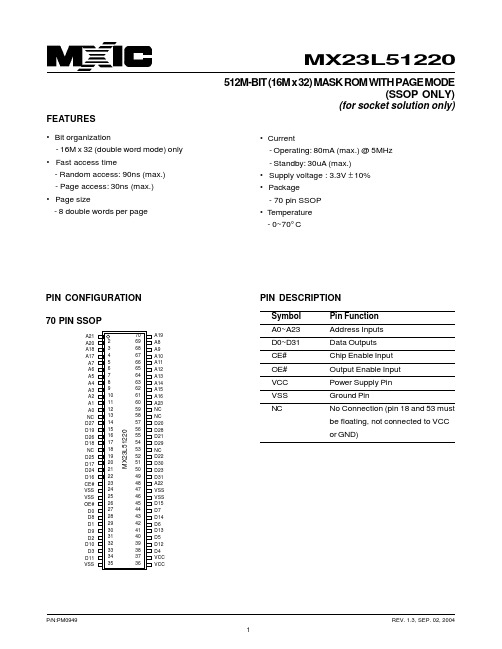
P/N:PM0949
REV. 1.3, SEP. 02, 2004
2
元器件交易网
MX23L51220
DC CHARACTERISTICS (Ta = 0° C ~ 70° C, VCC = 3.3V ± 10%)
Item Output High Voltage Output Low Voltage Input High Voltage Input Low Voltage Input Leakage Current Output Leakage Current Operating Current Symbol VOH VOL VIH VIL ILI ILO ICC MIN. 2.4V 2.2V -0.3V MAX. 0.4V VCC+0.3V 0.2xVCC 10uA 10uA 80mA Conditions IOH = -0.4mA IOL = 1.6mA
MACHale Waihona Puke ONIX AMERICA, INC.
TEL:+1-408-262-8887 FAX:+1-408-262-8810
http : //
MACRONIX INTERNATIONAL CO., LTD. reserves the right to change product and specifications without notice.
AC Test Conditions
Input Pulse Levels Input Rise and Fall Times Input Timing Level Output Timing Level Output Load 0.4V~ 2.8V 10ns 1.5V 1.5V See Figure
MDZ20IU-037说明书

T O L E R A
GRADE F M C V SCALE
0.5<R≤6 `0.05 `0.1 `0.2 6<R≤30 `0.1 `0.2 `0.5 `1
ANGLE FM CV 图幅 5' 30' 单位 30' 1~
A4 共 1张 第 1张 mm 比例 1:1
第一角画法
30<R≤120 `0.15 `0.3 `0.8 `1.5 1~ 2~ 版本 (Version) A/0 批准/日期
产品型号 Model
材料标记
洪杜莹/2020.09.14 图号
MDZ20IU-037
F
N C E
120<R≤400 400<R≤1000
`0.2 `0.5 `1.2 `2.5 2~ `0.3 `0.8 `2 `4 -
5~ -
审核/日期 美智光电科技股份有限公司
mm 1000<R
`0.5 `1.2 `3 `6 - -
设计/日期
叶 波/2020.09.14 零件名称 付金雅/2020.09.14Part name
说明书 16100101005842
3
4
5
6
7
8
c
A
d
A
机密
B
B
C
C
D
来料需十字折折好
D
E
技术要求:
1、尺寸:100x100mm
F
2、材料:双胶纸80g
3、黑色边框为裁切线
4、物料应符合企标“QMZ-J53.021
产品说明书技术条件”的要求
1
2
E
图号 (Drawing No.)
材Hale Waihona Puke 描述(Material) 表面处理 (Treatment) Ⅰ Ⅱ Ⅲ Ⅳ Ⅴ Ⅵ Ⅶ Ⅷ Ⅸ Ⅹ 备注(Remark)
20K调试培训教材1

亮
在加速时,速度>0.1 在加速时,速度>0.1 m/s 两个主接触器都闭合 (201:1, 202:2,204) 从LCECPU来的主接触器 LCECPU来的主接触器 激活命令有效 所有厅门关闭 轿门关闭 关门命令有效 需要驱动 变频器准备好运行 在轿门关闭后安全回路 正常 轿厢内的开门命令有效 轿厢内的开门按钮有效 光电管的光源被阻挡 关门强迫极限要求重新 开门
4
、LCEDRV板部分LEDs的描述 LCEDRV板部分 板部分LEDs的描述
DRVLEDS描述表 DRVLEDS描述表
LEDs Overload(黄色) Overload(黄色) Full Load(黄色) Load(黄色) 61:U(黄色) 61:U(黄色) 61:N (黄色) CH B(黄色) B(黄色) CH A(黄色) A(黄色) Change Board(红色) Board(红色) Cpu Running(绿色) Running(绿色) Thermistor (红色) (红色) Up dir(黄色) dir(黄色) Down dir(黄色) dir(黄色) High speed(黄色) speed(黄色) Low speed(黄色) speed(黄色) Brake Open(黄色) Open(黄色) Service speed(黄色) speed(黄色) Stop(黄色) Stop(黄色) V3F10Fault(红色) V3F10Fault(红色) V3FMCEn(黄色) V3FMCEn(黄色) 含义 超载信号输入 满载信号输入 61:U信号输入 61:U信号输入 61:N信号输入 61:N信号输入 读码器B 读码器B 通道信号输入 读码器A 读码器A 通道信号输入 DRV板故障 DRV板故障 DRV运行 DRV运行 热敏电阻输入 上行输出 下行输出 高速输出 低速输出 抱闸打开信号输出 中速输出 使能信号输出 变频器故障信号输入 主接触器闭合信号输出
JM20330中文资料

JMicron/JM20330JM20330Serial ATA Bridge ChipDescriptionJMicron’s JM20330 is a single chip solution for serial and parallel ATA translation. It includes the Serial ATA PHY , Link, Transport, and Parallel ATA (application layer) controller. The Serial ATA physical, link, and transport layers are compliant to Serial ATA 1.0. JM20330 supports a 1.5GHz data rate, and scalable to 3.0 GHz data rate by directly doubling the internal clock source. The application layer supports both the A TA register command set and PACKET command set, which could drive both Hard Disk Drive and ATAPI Optical Storage such as CR-ROM, CD-RW, DVD-ROM, DVD-RW, etc. The Serial ATA and the Parallel ATA application layer support both host and device operation and can be configured through a single pin.Quick ReferenceSignal Bit Rate 3.0/1.5 Gbps Spread Spectrum -3.0% to 0.0 Power Supply 3.3V and 1.8V ESD Protection 2000 V Host and Device Programmable Adj. Amplitude 2 levels Adj. Pre-emphasis 4 levels Package 64-pin TQFP ApplicationsAll SATA products Mass storage devices Optical storage Dongle bridge Storage systemFeaturesSerial ATA 1.0 Specification compliant Automatic Serial ATA 3.0/1.5 Gbps speed negotiationATA/ATAPI PIO mode 0 to 4ATA/ATAPI Ultra DMA of transfer rate 16.7, 25, 33, 48, 66, 100, 133, and 150MB/s. ATA/ATAPI LBA48 addressing mode associated with 2-byte sector count Support Serial ATA hot-plug Ultra low power consumptionWork for both AC and DC couple between the transmitter and the receiverProvide specified OOB signal detection and transmissionSupport Spread Spectrum Clocking to reduce EMISupport 20MHz, 25MHz, 30MHz or 40MHz Reference ClockSupport Partial/Slumber power management Provide adjustable TX signal amplitude and pre-emphasis level Master/Slave supportVersion 1.0May 2003 © JMicron 2003. All rights reserved.Page 1Copying prohibited.“Œ‹ž“s •¢“c ’J ‹æŽO Œ¬’ƒ‰® 2-11-22 ƒT ƒ“ƒ^ƒ••[ƒY ƒZ ƒ“ƒ^•[ƒrƒ‹•@•§154-8539•@/•@TEL: 03 (3487) 8502 / FAX: 03 (3487) 8825 / e-mail: jmicron@ ‘å•ãŽs—…•ì‹æ•¼’†“‡ 3-7-13 •V‘å•ãƒT ƒN ƒZ ƒX ƒrƒ‹EAST•@•§532-0011•@/•@TEL: 06(6885) 1688 / FAX: 06 (6885) 1721 /–{ŽÐŠÖ•¼‰c ‹Æ•ŠJMicron/JM20330Functional Block DiagramRXP/RXN GIO0GIO1TXP/TXNMODE[2:0]Device BridgeHost BridgePC IDE PortHDD/Optical StorageVersion 1.0May 2003 © JMicron 2003. All rights reserved. Page 2Copying prohibited.Fig. 1 Functional Block Diagram of JM20330ApplicationsFig. 2 JM20330 Host and Device bridge system diagramProduct InformationName DescriptionJM20330 Serial ATA Bridge ChipDesign KitContact Information 1 JM20330 Data Sheet Department Email 2 JM20330 Design GuideSales sales@ Application EVBTech. Support 3fae@“Œ‹ž“s •¢“c’J ‹æŽO Œ¬’ƒ‰® 2-11-22 ƒT ƒ“ƒ^ƒ••[ƒY ƒZ ƒ“ƒ^•[ƒrƒ‹•@•§154-8539•@/•@TEL: 03 (3487) 8502 / FAX: 03 (3487) 8825 / e-mail: jmicron@ ‘å•ãŽs—…•ì‹æ•¼’†“‡ 3-7-13 •V‘å•ãƒT ƒN ƒZ ƒX ƒrƒ‹EAST•@•§532-0011•@/•@TEL: 06(6885) 1688 / FAX: 06 (6885) 1721 /–{ŽÐŠÖ•¼‰c ‹Æ•Š。
MAA50-2S0312SBP中文资料

元器件交易网
Switching Power Supplies МАА Series MAA50
Output settings
№ pin Single-channel Dual-channel Triple-channel
1 case case case
Single-output models
Module
Output power Output voltage Output current
МАА501S03SХХ
26,4 W
3,3 VDC
8A
МАА501S05SХХ
40 W
5 VDC
8А
МАА501S12SХХ
12 VDC 4,17 А
МАА501S15SХХ
元器件交易网
Switching Power Supplies МАА Series MAA50
Ordering information
МАА 50 – 3 S 05 15 15 S U N c d efg h ijkl
c - MAA Series d - Nominal output power, Watt e - Channel quantity (1, 2, 3) f - - Input voltage
~ out/out 500
Insulation resistance
Voltage 500VDC
20
High humidity
Temperature 35°С
98
Cyclic overpatching of temperature
– 60
+85
Multiple mechanical shocks