德劲DE1123使用说明书
Eaton DE11 变速开关说明书

Eaton 180654Eaton DE11 Variable speed starters, Rated operational voltage 230 V AC, 1-phase, Ie 7 A, 1.5 kW, 2 HP, Radio interference suppression filter DE11-127D0FN-N20NGeneral specificationsEaton DE11 Variable speed starter 180654DE11-127D0FN-N20N 4015081758197169 mm 230 mm 45 mm 1.04 kg UL 508CUL report applies to both US and Canada RCMSafety requirements: IEC/EN 61800-5-1 ULIEC/EN61800-5 CSA-C22.2 No. 14Specification for general requirements: IEC/EN 61800-2 UL File No.: E172143 IEC/EN61800-3 CECertified by UL for use in Canada RoHS, ISO 9001 IEC/EN 61800-3 CULUL Category Control No.: NMMS,Overload cycle for 60 s every 600 sProduct NameCatalog Number Model CodeEANProduct Length/Depth Product Height Product Width Product Weight Certifications Catalog Notes240 V2.79 kVA7 A1.5 kW6.8 AIs the panel builder's responsibility. The specifications for the switchgear must be observed.230 V AC, 1-phase240 V AC, 1-phaseMeets the product standard's requirements.1.5 kW250 VMeets the product standard's requirements.-40 °C200 VRadio interference suppression filterPC connection0 Hz60 °C DX-COM-STICK3_ConnectionUpdate DX-COM-STICK3How does the internal motor protection work?Access to Parameter Level 2 Parameter Lock Load DefaultSet point settingStarting, Stopping and OperationElectromagnetic compatibility (EMC)Conformal CoatingQuick-Start-Guide DE1 (english)The OP System Bus - Parameterizing - ControlFire modeMotor data Motor Protection V/f curves Slip Compensation Connecting drives to generator suppliesI/O ConfigurationQuick-Start-Guide DE11 (english)HVAC, water/wastewater and industrial mediums - brochure Number 1 in efficiency The easiest way of variable motor speed PowerXL DE1 Variable Speed StarterDA-SW-drivesConnectDA-SW-Codesys 2 SWD for DC1 and DE1DA-SW-drivesConnect - InstallationshilfeDA-SW-DE1 ModbusRTU V1_00 LibraryDA-SW-DE11 CANopen CODESYS2 LibraryDA-SW-drivesConnect - installation helpDA-SW-Codesys 3 SWD for DC1 and DE1DA-SW-USB Driver DX-COM-STICK3-KITDA-SW-DE11 CANopen ConfigFile 210DA-SW-DE11 CANopen CODESYSV3 LibraryDA-SW-USB Driver PC Cable DX-CBL-PC-1M5DA-SW-drivesConnect USB Driver DX-COM-PCKITDA-SW-DE11 CANopen ConfigFile 203DA-SW-Driver DX-CBL-PC-3M0Product Range Catalog Drives EngineeringDrives - Product range catalogMains voltage - maxApparent power at 230 VRated operational current for specified heat dissipation (In) Rated operational power at 220/230 V, 50 Hz, 1-phase Assigned motor current IM at 440 - 480 V, 60 Hz, 150% overload 10.11 Short-circuit ratingRated operational voltage10.4 Clearances and creepage distancesOutput at quadratic load at rated output voltage - maxOutput voltage - max10.2.3.1 Verification of thermal stability of enclosuresAmbient storage temperature - minMains voltage - minFitted with:Output frequency - minAmbient operating temperature at 150% overload - max Starting current - max Application notes Brochures Catalogs200 %, IH, max. starting current (High Overload), For 1.875seconds every 600 seconds, Power section6.3 A60 °CModbus RTU, built inOP-Bus (RS485), built inCANopen®, built in2 HP300 Hz230 V AC, 3-phase240 V AC, 3-phase16 kHz, 4 - 32 kHz adjustable (audible), fPWM, Power section, Main circuitParameterization: drivesConnectParameterization: drivesConnect mobile (App) Parameterization: FieldbusParameterization: KeypadOperation (with 150 % overload)-10 °C≤ 0.6 A (max. 6 A for 120 ms), Actuator for external motor brakeDoes not apply, since the entire switchgear needs to be evaluated.7 A DA-DC-00004551.pdfDA-DC-00004556.pdfeaton-frequency-inverter-dimensions-009.eps eaton-frequency-inverter-3d-drawing-017.epsDA-CE-ETN.DE11-127D0FN-N20NIL040005ZUPowerXL DE1 variable speed starterMN040003_ENMN040018_ENMN040019_ENMZ040046_ENMN040011_ENDA-CS-de1_fs1_ip20DA-CD-de1_fs1_ip20Assigned motor current IM at 230 V, 50 Hz, 150% overload Ambient operating temperature - maxCommunication interfaceAssigned motor power at 115/120 V, 60 Hz, 1-phase Output frequency - maxOutput voltage (U2)Switching frequencyFeaturesHeat dissipation detailsAmbient operating temperature - minBraking currentNumber of HW-interfaces (serial TTY)10.6 Incorporation of switching devices and components Nominal output current I2N Certification reports DrawingseCAD model Installation instructions Installation videos Manuals and user guidesmCAD modelAssigned motor current IM at 220 - 240 V, 60 Hz, 150% overload 6.8 A10.2.6 Mechanical impactDoes not apply, since the entire switchgear needs to be evaluated.10.3 Degree of protection of assembliesDoes not apply, since the entire switchgear needs to be evaluated.Assigned motor current IM at 115 V, 50 Hz, 150% overload6.3 AProduct categoryVariable speed starterRadio interference classC2, C3: depending on the motor cable length, the connected load, and ambient conditions. External radio interference suppression filters (optional) may be necessary.C1: for conducted emissions onlyOptional external radio interference suppression filter for longer motor cable lengths and for use in different EMC environmentsAssigned motor current IM at 110/120 V, 60 Hz, 150% overload 6.8 AHeat dissipation capacity Pdiss0 WAssigned motor power at 460/480 V, 60 Hz, 3-phase2 HPNumber of HW-interfaces (RS-422)Mains current distortion120 %ProtocolMODBUSEtherNet/IPOther bus systemsCAN10.9.2 Power-frequency electric strengthIs the panel builder's responsibility.Overvoltage categoryIIIDegree of protectionIP20NEMA OtherAmbient storage temperature - max70 °CRated impulse withstand voltage (Uimp)2000 VOutput at linear load at rated output voltage - max1.5 kWLeakage current at ground IPE - max< 3.5 mA (AC-operated)< 10 mA (DC-operated)Converter typeU converterFrame sizeFS110.2.2 Corrosion resistanceMeets the product standard's requirements.Supply frequency50/60 Hz10.2.4 Resistance to ultra-violet (UV) radiationMeets the product standard's requirements.10.2.7 InscriptionsMeets the product standard's requirements.Shock resistance15 g, Mechanical, According to IEC/EN 60068-2-27, 11 msApplication in domestic and commercial area permittedYesNumber of inputs (analog)1 (parameterizable, 0 - 10 V DC, 0/4 - 20 mA)Number of phases (output)310.12 Electromagnetic compatibilityIs the panel builder's responsibility. The specifications for the switchgear must be observed.10.2.5 LiftingDoes not apply, since the entire switchgear needs to be evaluated.Number of HW-interfaces (RS-485)1Number of HW-interfaces (industrial ethernet)10.8 Connections for external conductorsIs the panel builder's responsibility.ProtectionFinger and back-of-hand proof, Protection against direct contact (BGV A3, VBG4)Number of relay outputs1 (parameterizable, N/O, 6 A (250 V, AC-1) / 5 A (30 V, DC-1))Application in industrial area permittedYesClimatic proofing< 95 average relative humidity (RH), no condensation, no corrosionConnection to SmartWire-DTIn conjunction with DX-NET-SWD3 SmartWire DT moduleYesStatic heat dissipation, non-current-dependent Pvs0 W10.9.3 Impulse withstand voltageIs the panel builder's responsibility.Voltage rating - max240 VOverload current IL at 150% overload10.5 AInput current ILN at 150% overload17.4 ANumber of HW-interfaces (RS-232)Number of inputs (digital)4 (parameterizable, 10 - 30 V DC)Rated control supply voltage10 V DC (Us, max. 0.2 mA)Cable lengthC3 ≤ 25 m, Radio interference level, maximum motor cable lengthC2 ≤ 10 m, Radio interference level, maximummotor cable lengthC1 ≤ 5 m, Radio interference level, maximum motor cable length10.5 Protection against electric shockDoes not apply, since the entire switchgear needs to be evaluated.Mounting positionVerticalMains switch-on frequencyMaximum of one time every 30 seconds10.13 Mechanical functionThe device meets the requirements, provided the information in the instruction leaflet (IL) is observed.10.9.4 Testing of enclosures made of insulating materialIs the panel builder's responsibility.Heat dissipation per pole, current-dependent Pvid0 WElectromagnetic compatibility1st and 2nd environments (according to EN 61800-3)Resolution0.03 Hz (Frequency resolution, setpoint value)Assigned motor power at 460/480 V, 60 Hz2 HPRelative symmetric net voltage tolerance10 %Equipment heat dissipation, current-dependent Pvid59 WRated operational current (Ie)7 A at 150% overload (at an operating frequency of 16 kHz and an ambient air temperature of +50 °C)Number of outputs (analog)Suitable forBranch circuits, (UL/CSA)Apparent power at 240 V2.91 kVANumber of HW-interfaces (USB)Operating modeSpeed control with slip compensationU/f controlRated frequency - min45 HzDelay time< 10 ms, On-delay< 10 ms, Off-delayNumber of outputs (digital)Power consumption59 W10.2.3.2 Verification of resistance of insulating materials to normal heatMeets the product standard's requirements.10.2.3.3 Resist. of insul. mat. to abnormal heat/fire by internal elect. effectsMeets the product standard's requirements.Number of HW-interfaces (other)Rated frequency - max66 HzVibrationResistance: According to EN 61800-5-1Short-circuit protection (external output circuits)Type 1 coordination via the power bus' feeder unit, Main circuit10.7 Internal electrical circuits and connectionsIs the panel builder's responsibility.Braking torqueMax. 30 % MN, Standard - Main circuitAdjustable to 100 %, DC - Main circuitAmbient operating temperature at 150% overload - min-10 °CRelative symmetric net frequency tolerance10 %10.10 Temperature riseThe panel builder is responsible for the temperature rise calculation. Eaton will provide heat dissipation data for the devices.Eaton Corporation plc Eaton House30 Pembroke Road Dublin 4, Ireland © 2023 Eaton. All Rights Reserved. Eaton is a registered trademark.All other trademarks areproperty of their respectiveowners./socialmedia6.3 A2 HP137 W at 25% current and 0% speed 37 W at 25% current and 50% speed 44.6 W at 50% current and 0% speed 44.9 W at 50% current and 50% speed 51.6 W at 50% current and 90% speed 62.4 W at 100% current and 0% speed 68.9 W at 100% current and 50% speed 78.4 W at 100% current and 90% speed 20 A, UL (Class CC or J), Safety device (fuse or miniature circuit-breaker), Power Wiring 0Max. 2000 mAbove 1000 m with 1 % derating per 100 mAssigned motor current IM at 400 V, 50 Hz, 150% overload Number of HW-interfaces (parallel)Assigned motor power at 230/240 V, 60 Hz, 1-phase Number of phases (input)Heat dissipation at current/speed Short-circuit protection ratingNumber of interfaces (PROFINET)Altitude。
电子萨克森数字点火ZDG 3.23安装手册说明书

ELEKTRONIKSACHSEPage 1of 13FunctionELEKTRONIKSACHSEElektronik Sachse MHP GmbH &Co.KGInstallation ManualDigital Ignition ZDG 3.23(Ducati Beveldrive Bosch)Item:Z53version:5bbf6cbContents1Function .......................................................................12Scope of Delivery ...............................................................33Mounting .......................................................................34Electrical Connections ..........................................................55Initial Setup .. (86)Troubleshooting (11)1FunctionT he d i g it a l i gn iti on k it Z DG 3r ep l aces o ri g i na l e l ec tr on i c i gn iti on un it s as we ll as o l d po i n t s including the weights advancer or manual advance wires.Func ti on :S t a rti ng fr om T D C t he momen t a ry pe ri phe r a l speed i s ca l cu l a t ed o v e r 300°and by this means,the time up to ignition is calculated per crank turn.Because the peripheral speed varies substantially during acceleration,a rather long time frame for measurement was chosen in order to achieve a relatively exact measurement.T he compu t a ti on o f i gn iti on ti m i ng i s d ivi ded i n t o t h r ee r anges ,see t ab l e 1on t he ne xt page.T he i gn iti on bo x f ea t u r es an ad j us t ab l e r e v li m it e r.T ha t means t he ma xi mum eng i ne speed depends on t he se tti ng o f t he r e v li m it e r and m i gh t be l owe r t han t he t ab l e i nd i ca t es .For more information see chapter 5on page 8.Table1RPM ranges of the ignition box.Range Function0–400rpm Starting range,ignition always at TDC to prevent engine kickback and ease starting400–1000rpm Idling range,typically2°to8°advance,depending on the selectedcurve1000–12,000rpm Partial load range–maximum load range,the main advance adjustment takes place here,depending on the curve selectionT he l ow r ange de li be r a t e ly has no i gn iti on ad v ance t o r educe k i ckback and a l so he l p e l ec tri c s t a rt e r s and it s gea r s.A t t h i s l ow eng i ne speed t he eng i ne doesn’t need ad v ance. This is true for all selectable ignition curves.T he m i d r ange i s somehow a“s t a ti c ad v ance”.S t a ti c because it’s used f o r t he eng i ne s t a rti ng and l ow i d l e and mo r e o r l ess co rr esponds t o t he tr ad iti ona l s t a ti c ad v ance fr om a f unc ti ona l po i n t o f vi ew,a lt hough it i s se t up en tir e ly i n so ft wa r e,i n con tr as t t o a mechan i ca l static advance.The amount of static advance depends on the choice of ignition curve and is usually between2°–8°.T he l as t r ange i s t he ac t ua l ope r a ti ng r ange and t he ad v ance i s se t d y nam i ca lly acco r d i ng to the selected ignition curve.Wasted SparkT he i gn iti on uses t he so ca ll ed was t ed spa r k p ri nc i p l e.T ha t means t ha t e v e ry c r anksha ft r o t a ti on a spa r k i s gene r a t ed.T h i s i s i ndeed a de li be r a t e des i gn dec i s i on and canno t be changed.It m i gh t sound i ne ffi c i en t a t fir s t,bu t ac t ua lly doesn’t ha v e much i mpac t o r drawbacks.It’s a misconception that a wasted spark system uses twice the energy.A spark plug in a comp r essed c yli nde r r equ ir es app r o xi ma t e ly12k V t o gene r a t e a spa r k.A spa r k p l ug i n a noncomp r essed c yli nde r r equ ir es app r o xi ma t e ly2k V t o gene r a t e a spa r k.T h i s means that the coil doesn’t discharge all it’s energy when the spark is“wasted”,but only a small amount.Ano t he r m i sconcep ti on i s t ha t was t ed spa r k s y s t ems don’t r e v t ha t h i gh.Ou r s y s t ems ha v e been eng i nee r ed t o be compa ti b l e w it h co il s w it h a p ri ma ry r es i s t ance be t ween2Ω–5Ωwh i ch a ll ows an op ti ma l dwe ll f o r up t o12,500r pm,wh i ch i s su it ab l e e v en f o r mos t t wostroke engines.Special built versions go up as high as18,000rpm.Function Page2of13ELEKTRONIKSACHSEELEKTRONIKSACHSEPage 3of 13Scope ofDeliveryFigure 1Scope of delivery.2Scope of DeliveryF i gu r e 1shows wha t’s supposed t o be i n t he package .No t e t ha t i n some cases t he i mage ma y no t show t he mos t up -t o -da t e v e r s i on .We a l so m i gh t add ,change o r r emo v e components.If there are any discrepancies or questions,don’t hesitate to reach out to us.3Mounting•Remo v e a ll Bosch componen t s ,t he tri gge r whee l on t he c r anksha ft needs t o be r emo v ed as well.•Mount the new pickup plate with the original 9mm sleeve hub.•Pu t t he s l ee v e hub on t he c r anksha ft and t hen pu t t he magne t d i sk on t he s l ee v e hub until it reaches the neck.•The M30nut can now again be mounted (with medium strength thread lock).•T he sea li ng o f t he cab l e f eed t h r ough t akes p l ace b y t he p r o vi ded M 16cab l e g l and .An cable gland adapter to M22is provided.Mounting Page 4of 13ELEKTRONIKSACHSE1234If t he o ri g i na l co il s come w it h sepa r a t e r es i s t o r s ,t hose can be r emo v ed .Res i s t o r s a r e not required with this ignition kit.E x cep t f o r co il s fr om a 2-s tr oke eng i ne and C D I ty pes ,nea rly a ll ty pes o f new o r used i gn iti on co il s can be used .T he on ly t echn i ca l r equ ir emen t o f t he co il i s a p ri ma ry r es i s t ance o f 2Ω–5Ω.T he co il s f o r t he d iff e r en t c yli nde r s shou l d be o f t he same ty pe .No t e t ha t t he r e a r e a f ew co il s ou t t he r e w it h on ly one (+)connec t o r,t he nega tiv e one i s connec t ed t o g r ound .T hose co il s a r e no t su it ab l e w it h t h i s i gn iti on because it’s no t poss i b l e t o r ou t e t he −connection to the ignition box.T o measu r e t he p ri ma ry r es i s t ance ,d i sconnec t t he con t ac t s o f t he co il and measu r e t he resistance between the plus and minus contacts with a multimeter.ELEKTRONIKSACHSEPage 5of 13Electrical Connections4ElectricalConnectionsIgnition circuit diagram,also connect the test LEDs for the latersettingComplete diagramTable2details how the ignition box is wired up.T he i gn iti on bo x f ea t u r es t wo g r ound connec ti ons:2and9.E it he r o f wh i ch can be used. If poss i b l e bo t h shou l d be connec t ed.O ne as a backup,t o ensu r e a good g r ound connec ti on. But that’s not required,connecting only a single one will work.T he w ir e c r oss sec ti on o f t he g r ound cab l e shou l d no t be be l ow1.5mm2and shou l d be kep t as sho rt as poss i b l e.T he w ir e c r osssec ti on o f t he o t he r cab l es shou l d no t be be l ow 0.5mm2.Crimping the FerrulesUse insulated wire end ferrules on the cables.The wire end ferrules might be too small to hold the wires.If that’s the case trim off a few strands of the wire so the wire fits into the ferrules.For crimping the wire end ferrules it’s best to use professional crimping pliers designed f o r t h i s pu r pose.Howe v e r,it can a l so be done w it h a p i pe w r ench.If unce rt a i n ty e xi s t s abou t t he qua lity o f t he c ri mp it’s poss i b l e t o so l de r t he f e rr u l es,bu t t ha t shou l d be a v o i ded if possible.How crimping is done is detailed in figure2.Use on ly one f e rr u l e pe r w ir e.D o no t add a second l a r ge r f e rr u l e on t op o f a sma ll e r one.This in turn means,the pickup wires don’t need additional ferrules because they are already equipped with a set of ferrules.A tt en ti on:P l ease do no t sho rt en t he p i ckup l ead.Co il up e x cess w ir e and fix it w it h cable ties.Table2Terminal connections on the ignition box.Connector Function1Ignition coil cylinder vertical−2Ground3Pickup lead,brown4Pickup lead,green5Pickup lead,yellow6Pickup lead,white7Output for electronic tachometer8+12V supply voltage,switched9Ground(same as#2)10Ignition coil cylinder horizontal−Electrical Connections Page6of13ELEKTRONIKSACHSEELEKTRONIKSACHSEPage 7of 13ElectricalConnectionsStrip the insulation off the wire end.Place the ferrule as far as it goes over the wire.Using a professional crimp tool to crimp theferrule.Using a pipe wrench to crimp the ferrule.In case the wire doesn’t fit into the ferrule,strip off a few strands.The finished crimp should look like this and not come off when pulled firmly.Figure 2Crimping the wire end ferrules.Spark Plugs /Spark Plug CapsMake su r e y ou use a r es i s tiv e componen t i n t he cha i n .T h i s usua lly i s done b y us i ng i n t e rf e r ence fr ee caps f o r t he spa r k p l ugs .A r es i s tiv e componen t i s on ly needed a t one po i n t i n t he i gn iti on s y s t em .T h i s can be e it he r a sh i e l ded spa r k p l ug ,a sh i e l ded spa r k p l ug cap ,a sh i e l ded H T l ead o r a sepa r a t e r es i s t o r t ha t goes i n be t ween t he H T l ead (a ty p i ca l).Us i ng t he w r ong p l ug caps ma y r esu lt i n an un r e li ab l e i gn iti on as t he y i n t e rf e r e w it h t he electronics.Recommended are NGK caps with 5kΩinternal resistance.A n y spa r k p l ug can be used w it h ou r i gn iti on s y s t ems .No spec i a l r equ ir emen t s t he r e .Just note that if a resistive spark plug is used,a resistive plug cap is not required.Minimum VoltageThe ignition requires a minimum voltage of 7.5V to operate.The supply voltage must not f a ll be l ow t h i s v a l ue a t an y ti me .T h i s v a l ue canno t be measu r ed w it h a s t anda r d mu lti me t e r.It w ill r ead much h i ghe r v a l ues if t he i gn iti on a lr ead y s t a rt s t o cu t ou t because o f unde rv o lt age .T he l oad o f t he b i ke e l ec tri cs ,espec i a lly t he i gn iti on co il(s )cause sho rt v o lt age dips that are hard to measure with a multimeter.An oscilloscope or similar equipment is required to perform proper undervoltage analysis.T ha t ha vi ng sa i d,it shou l d be no t ed t ha t t he i gn iti on pe rf o r ms we ll unde r l ow v o lt age conditions.And often if the engine cuts out,it’s in fact the coil not producing a spark any longer rather than the ignition stopping to work.5Initial SetupT he ad j us t men t o f t he be v e l d riv e i s r a t he r comp li ca t ed i n f ac t o f t ha t t he magne t d i sk and the pickups are mounted on different engine parts(crankshaft and side cover).One must lift aga i n e v e ry ti me t he s i de co v e r f o r co rr ec ti ng t he ti m i ng.Howe v e r,t he co v e r mus t no t be screwed every time.•The position marking on the magnet wheel should match with the groove of the sleeve.Tighten one of the set screws only slightly.The magnet wheel should fit on the primary gear.•Senso r he i gh t ad j us t men t:Moun t t he s i de co v e r t empo r a rily,t u r n on t he i gn iti on sw it ch and t u r n t he eng i ne on.T he L ED i nd i ca t o r s shou l d r espond t o and sw it ch on and o ff a t every turn.In case of no function,the magnet wheel should be moved forward slightly (about1mm).Then repeat the test.•T ake ca r e t ha t t he magne t s i n t he d i sk a r e app r o xi ma t e ly i n t he same he i gh t as t he sensor,see figure3.Figure3Ensure correct alignment of magnet disk and sensor.•I gn iti on ad j us t men t:Mo v e t he ho ri zon t a l p i st on abou t t o B D C.Now t u r n on t he i gn iti on sw it ch and con ti nue t u r n i ng un til t he r ed L E D t u r ns on fir s t and t hen t u r ns o ff.T he p i s t on i s now an es ti ma t ed10°be f o r e T D C.Now comes t he s li gh tly anno yi ng pa rt o f t he se tti ng.T he s i de co v e r mus t be r emo v ed and t he a l um i n i umd i sk mus t be t u r ned b y t h i s amoun t coun t e rc l ockw i se.T hen aga i n as abo v e.T he a i m i s t ha tt he L ED goes ou t ri gh t i n t he T DC.If t he co rr ec t pos iti on i s f ound,a ll t h r ee se t sc r ews i n the aluminium disk must be tightened(with medium strength thread lock).If t he magne t d i sk happens t o ha v e t wo pa ir s o f N and S magne t s,it doesn’t ma tt e r wh i ch pa ir i s used f o r t he i n iti a l se t up.It i s a l so no t r e l e v an t wh i ch T DC(comp r ess i on s tr oke o r exhaust stroke)is used for the initial setup.F i na lly secu r e t he se t sc r ews w it h med i um s tr eng t h t h r ead l ock compound.T h i s i s bes t done a ft e r t he i n iti a l se t up i s fi n i shed and accu r a t e.T hen r emo v e on ly one o f t he se t sc r ews, so t he pos iti on o f t he magne t d i sk doesn’t change.A pp ly a sma ll amoun t o f t h r ead l ock compound and re-tighten the set screw.Repeat with the other set screw(s).Initial Setup Page8of13ELEKTRONIKSACHSEELEKTRONIKSACHSEPage 9of 13Initial SetupT he D I P sw it ches a r e on t he l e ft s i de o f t he i gn iti on bo x.D I P sw it ch No .1con tr o l s t he rev limiter.It has two settings:up and down :DIP switch 1Rev limiter settingup 9,600rpm down 9,100rpmIf none o f t hese t wo r e v li m it e r se tti ngs a r e su it ab l e f o r t he b i ke ,t he bo x can be sen t i n for reprogramming of the rev limiter.T wo new values can then beprogrammed.Figure 4DIP switches and rotary switch.T he r e v li m it e r D I P sw it ch No .2i s ne xt t o D I P switch No.1and adjusts the frequency of the electronic tachometer that can be connected to termina l connec ti on 7o f t he i gn iti on bo x.If no e l ec tronic tachometer is connected this switch can be ignored.D I P sw it ch No .2shou l d be i n t he up pos iti on f o rcrankshaft frequency selection and down position for camshaft frequency selection:DIP switch 2Frequency settingup crankshaft down camshaftT he i gn iti on cu rv es can be se t us i ng t he r o t a ry d i a l on t he l e ft s i de o f t he bo x,ri gh t o f t he D I P sw it ches .Cu rv e No .0i s a t es t mode (a l so see sec ti on “T es t Mode ”on page 11)i n wh i ch t he bo x con ti nua lly fir es w it hou t t he eng i ne r unn i ng .T h i s t es t s t he i ns t a ll a ti on o f the units and coils.But it doesn’t test the pickup.Rotary switch settings 1–9are the different ignition curves.Which Ignition Curve to ChooseT he cho i ce o f cu rv e depends on t he comp l e t e s y s t em ,eng i ne ,ca r bu r e tt o r,e x haus t,eng i ne tuning,mono or dual plugged heads,etc.Furthermore,it depends on your personal preferences .D iff e r en t cu rv es m i gh t be app li cab l e on t he same b i ke f o r d iff e r en t d rivi ng cha r ac teristics,e.g.racing or touring.D ual plugged heads require less advance.A part from that it’s not that easy to find the op ti ma l cu rv e .D iff e r en t cu rv es change t he cha r ac t e ri s ti cs ,so it’s no t eas y t o p i npo i n t a cu rv e be i ng “be tt e r”t han ano t he r one ,r a t he r t han “d iff e r en t”.A d y namome t e r su r e ly he l ps fi nd i ng a good cu rv e f o r t he b i ke and use case .J us t tryi ng d iff e r en t cu rv es on t he r oad wo r ks as we ll.No ti ce t ha t some cu rv es on ly ha v e sub tl e d iff e r ences and y ou m i gh t no t ac t ua lly no ti ce a change .If t he eng i ne s t a rt s t o knock ,r educe t he ad v ance .It’s a c l ea r s i gn o f t oo much ignition advance.Initial SetupPage 10of 13ELEKTRONIKSACHSE0 10 20 30 40 50400 0 10002000 3000 4000 5000 6000 7000 8000 9000A d v a n c e /°R P M C u r v e 1 0 10 20 30 40 50400 0 1000 2000 3000 4000 5000 6000 7000 8000 9000A d v a n c e /°R P M C u r v e 21020304050400 0 1000 200030004000 5000 6000 7000 8000 9000A d v a n c e /°R P MC u r v e 3 01020 304050400 0 10002000 3000 4000 5000 6000 7000 8000 9000A d v a n c e /°R P M C u r v e 40 10 2030 40 50400 0 1000 2000 3000 4000 5000 6000 7000 8000 9000A d v a n c e /°R P MC u r v e5 0 1020304050400 0 1000 2000 30004000 5000 6000 7000 8000 9000A d v a n c e /°R P MC u r v e 61020 304050400 0 10002000 3000 4000 5000 6000 7000 8000 9000A d v a n c e /°R P M C u r v e 7 0 10 2030 40 50400 0 1000 2000 3000 4000 5000 6000 7000 8000 9000A d v a n c e /°R P M C u r v e 80 1020304050400 0 1000 2000 30004000 5000 6000 7000 8000 9000A d v a n c e /°R P MC u r v e 9Figure 5Selectable ignition curves.We ship the units with a suitable curve for the purchased model as default.If you don’t wan t t o fi dd l e w it h t he s y s t em,j us t l ea v e it t he r e.It i s a conse rv a tiv e cu rv e w it h no t t oo agg r ess iv e ad v ance so it does a good j ob as de f au lt cu rv e f o r a v a ri e ty o f b i ke con fi gu r a ti ons. O t he r w i se if it’s a s t ock b i ke,check t he manua l f o r ad v ance se tti ng t he manu f ac t u r e r recommends and select a suitable ignition curve based on that.6TroubleshootingTest ModeT he i gn iti on bo x f ea t u r es a t es t mode.T h i s mode make t he spa r k p l ug(s)fir e con ti nuous ly without the engine running.This tests the power supply,wiring,coils and the ignition box. However,it does not test the pickup.For a working ignition test mode has to succeed.T o use t es t mode,unsc r ew t he spa r k p l ug(s)and p l ace t hem back i n t o t he p l ug caps, so t he spa r k can be obse rv ed.T hen sw it ch t he10-wa y he x sw it ch on t he s i de o f t he bo x i n t o pos iti on’0’.T hen t u r n on t he i gn iti on.Y ou shou l d ge t a con ti nuous spa r k.If t ha t’s no t wha t’s happen i ng,check t he v o lt age be t ween g r ound(p i n2)and p i n8if it r eads12V. Sometimes it is required to turn the ignition off and on again to engage test mode.Check PickupIf t es t mode succeeds one can check t he p i ckup.Se l ec t an i gn iti on cu rv e(an y w ill do,e x cep t t es t mode).Unsc r ew t he spa r k p l ug(s)and p l ace t hem back i n t o t he p l ug caps,so t he spa r k can be obse rv ed and t u r n on t he i gn iti on.S l ow ly c r ank t he eng i ne b y hand and obse rv e t he LEDs on the pickup.They should turn ON and OFF if the magnets pass the sensors.If t he L E D s do no t li gh t up,check t he v o lt age be t ween t e r m i na l connec ti on p i n3and pin6while the ignition is turned on.It should read approximately5V.If t he L E D s cons t an tly s t a y e it he r on o r o ff,r ega r d l ess if t he magne t s pass t he senso r, then it’s likely that the pickup is damaged or the disk is misaligned to the sensors.T o check f o r m i sa li gnmen t y ou can unmoun t t he p i ckup and magne t d i sk and r econnec t t he p i ckup t o t he i gn iti on bo x.T hen ho l d bo t h i n y ou r hands and mo v e t he magne t ri ng t owa r ds t he senso r s.W it h t he S magne t pass i ng,t he L EDs shou l d go on,w it h t he N magne t passing,the LE D s should go off.If that works,then the magnet disk is probably misaligned and doesn’t pass the sensor while mounted in the bike.T he d i s t ance be t ween magne t and senso r,depend i ng on t he e x ac t mode l,shou l d be a r ound0.5mm–2mm.Mo r e i mpo rt an t t han t he d i s t ance i s t he a xi a l a li gnmen t(as j us t described).ELEKTRONIKSACHSE Page11of13TroubleshootingEngine doesn’t start or kicks backIf t he eng i ne wou l d no t s t a rt,o r t he eng i ne k i cks back,t hen t he i gn iti on ti m i ng i s w r ong.A s a gene r a l r u l e:Each ti me when a p i s t on r eaches T D C t he co rr espond i ng p l ug mus t gene r a t e a spark(at low rpms).It m i gh t be t ha t t he co il s a r e m ix ed up and t he r e f o r e t he ti m i ng f o r one o r mo r e c yli nde r s is off.Unscrew the spark plugs and turn on the ignition.Slowly crank the engine by hand and when a spa r k occu r s,check if t he co rr espond i ng p i s t on i s on T D C.It shou l d be f o r each cylinder.If it’s not,swap out the ignition cables with the cylinder that is(or reconnect the ignition coils).No t e t ha t a spa r k i s gene r a t ed a ft e r t he eng i ne s t ops f o r5s.T h i s spa r k can be i gno r ed during this test.Irregular Engine CutoutsIf some ti mes t he eng i ne suspends wh il e d rivi ng f o r2–3seconds and t hen keeps r unn i ng no r ma lly,t ha t means t ha t t he i gn iti on has been r ese t.T he cause f o r it can be a de f ec tiv e p l ug cap o r a l oose i gn iti on cab l e i n t he co il o r cap o r a bad g r ound connec ti on.Bu t i n mos t cases a bad con t ac t i n t he ope r a ti ng v o lt age supp ly(k ill sw it ch,s t a rt e r l ock,f use ho l de r, t e r m i na l s e t c.)causes t h i s e ff ec t.Some ti mes one c yli nde r o r t he en tir e i gn iti on ceases t o work and a power cycle of the ignition is required to restore operation.Fo r a t es t y ou can connec t a cab l e d ir ec tly fr om t he i gn iti on co il s and t he i gn iti on bo x to the positive terminal of the battery.Also put a second cable from the negative terminal of the battery to the ignition box(secure ground connection).If the engine is running well now y ou can assume an e rr o r i n t he w iri ng l oom.W it h con t ac t b r eake r s such a bad con t ac t i s no t no ti ceab l e,because a sho rt b r eak f o r a f ew m illi seconds o f t he supp ly v o lt age doesn’t matter,electronics in contrast are more sensitive to short power outages or surges.O ne cause o f irr egu l a r cu t ou t s i s a m i ss i ng r es i s tiv e componen t i n t he cha i n,see sec ti on “Spark Plugs/Spark Plug Caps”on page7.One or more Cylinders cut out when the Engine gets warmThis is likely an issue with the pickup.The pickup mounted by the engine gets warm and de v e l ops a bad con t ac t r esu lti ng i n a m i ss i ng s i gna l.If t he p r ob l em i s r ep r oduc i b l e and cu r es it se lf when t he eng i ne i s coo l ed down aga i n,t hen t he p i ckup shou l d be changed.It i s available as spare part(in case the warranty has expired).Troubleshooting Page12of13ELEKTRONIKSACHSERandom Spark occursIf some ti mes a spa r k i s gene r a t ed when t he p i s t on i s no t a t T D C,it m i gh t be t ha t ou r energy saving mode kicks in.If the ignition detects no engine movement for five seconds, it s t ops t he cu rr en t t o t he co il s t o p r e v en t it fr om o v e r hea ti ng as we ll as sa vi ng ene r g y.T h i s generates a spark.It’s a feature of the system to improve reliability and not a fault.LED on the Pickup does not completely turn offIt is not a fault if the LE D on the pickup does not completely turn off.Sometimes it is still s li gh tly g l ow i ng.T he i mpo rt an t pa rt i s t ha t it has t wo c l ea rly d i s ti ngu i shab l e s t a t es:O n and off or on and“almost off”.This doesn’t affect operation in any way.Tachometer shows half/twice the actual SpeedA n e l ec tr on i c t achome t e r connec t ed t o t he H T l ead o r co il m i gh t d i sp l a y t w i ce t he speed due to the wasted spark operation of the Z DG3.Therefore,this ignition features an output f o r an e l ec tr on i c t achome t e r.If t he t achome t e r s till shows a w r ong v a l ue fli p t he2nd D I P sw it ch(t he ri gh t one).T h i s a lt e r s t he fr equenc y o f t he t achome t e r ou t pu t.If it goes i n t o t he w r ong d ir ec ti on(speed i s qua rt e r ed o r quad r up l ed)t hen con t ac t us and we’ll p r o vi de a fix.Elektronik Sachse MHP GmbH&Co.KGBusestraße26a28213BremenGermany☎+49(0)54099069826✉info@elektroniksachse.de⌨www.elektroniksachse.deELEKTRONIKSACHSE Page13of13Troubleshooting。
德劲 DE1102
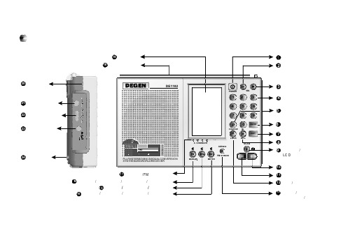
蜂鸣闹醒标志
时钟设置符号 锁定标志
ST BASS
VOL
W
FM MW SW N
PM
12
KHz MHz
3 MEM STEP
SSB
ERR
METER
/
音量指示
短波波段指示 兆赫兹 千赫兹 睡眠关机符号 米波段/秒钟 / 充电分钟指示
4. 快速点按数字键1 进入12 小时制式;点按数字键2进 入24小时 制式,按退出键可退出设置。
ENTER
1/2
+
点按数字键1或2
ENTER
提示:
在时钟制式选择模式下请快速对其进行选择,否则本机会退 出选择模式。 12小时制式时,“ PM”显示表示下午。
7
选择中波(MW)步进
中波(MW)广播电台频道间距(步进)视地区不同有所不同, 根据您所在地区选择频道间距。 北美和南美国家步进为:10KHz 其它国家(如中国): 9KHz
选择时钟制式
1. 取下电池并且断开外接电源适配器使收音机断电直至显示屏 无显示。
2. 再装入电池或接上外接电源适配器,本机进入设置等待模式, 显示屏有“SET”英文字样显示,右边有9~0的倒计时,如下图:
3. 待命模式下快速点按两次输入键进入时钟制式选择模式,显 示屏有“ 12-24”字样显示(如下图)并持续 3秒钟。
1
注意事项
不要试图给干电池充电。 新旧电池不要混在一起使用。 长时间不使用本机时,请取出电池。 切勿将充电电池与硬币或其它金属物 混放 ,以免电池短路导 致 发热或燃烧。 万一干电池漏液,请用软布擦净仓内液体以免腐蚀其它元件。
德西玛 DEX-M-18 电热水器 用户手册说明书

Online Warranty Registration歐盟A級能源效益認證EU ENERGY EFFICIENCY CLASS APlease read these instructions and warranty information carefullybefore use and keep them handy for future reference.U S E R M A N U A LContents請即進行保用登記﹗有關保用條款細則,請看本說明書最後一頁。
Please register your warranty information now !For Warranty Terms & Conditions,please refer to the last page of this user manual.2.Safety Instructions1.OverviewPart1-11 is intended for the specialist who is responsible for the installation of the appliance. Part2, 12 and 13 are for the end user. The provided manuals correspond to the technical specifications of the appliance.The latest version of the instructions can be found online at .NoticePlease read these instructions carefully before installing or using the appliance! Keep the instructions handy with the appliance for future use!- Do not use the appliance until it has been correctly installed and unless it is in perfect working order.- Do not remove the front cover under any circumstances before switching off the mains electrical supply to the unit.- Never make technical modifications, either to the appliance itself or the electrical leads and water pipes.- The appliance must be earthed at all times.- Pay attention to the fact that water temperatures in excess of approx. 43°C are perceivedas hot, especially by children, and may cause a feeling of burning. Please note that the fittings and taps may be very hot when the appliance has been in use for some time. - The appliance is only suitable for domestic use and similar applications inside closed rooms, and must only be used to heat incoming water from the mains supply. - The appliance must never be exposed to frost. - The values stated on the rating plate must be observed.- In case of malfunction, disconnect the fuses immediately. In case of leaks, cut off the mains water supply instantly. Repairs must only be carried out by the customer service department or an authorised professional.- This appliance can be used by children aged from 3 years and above and persons with reduced physical, sensory or mental capabilities or lack of experience and knowledge if they have been given supervision or instruction concerning use of the appliance in a safe way and understand the hazards involved. Children shall not play with the appliance. Cleaning and user maintenance shall not be made by children without supervision.2.安全守則2.Safety Instructions• If the appliance is factory equipped with a power supply cable, it must be replaced with an original spare cable from the manufacturer in case of damaged by an authorizedtechnician in order to avoid any hazards.• In accordance with VDE 0700, a circuit breaker with a contact opening gap of at least 3 mm for each pole must be provided on the mains side of the connecting box forappliances with a fixed connection.• The wall bracket must be secured with the supplied screws and dowels. The appliance must be secured to the wall bracket. The appliance may only be operated if it has been properly mounted on the wall bracket.• The prescribed nominal pressure stated on the rating plate may not be exceeded at any time.• The required water resistance may not fall below the value stated on the rating plate at any time. To observe additionally for pressure less installation:• The water outlet behind the devices must not be blocked, an d the water flow must not be restricted.• The water outlet facilities, such as shower head, jet control and other outlet unit, must be decalcified regularly. Deposits must be removed in regular intervals.• Only the fittings recommended by the manufacturer may be used.• If the appliance is exclusively connected to a single shower, only the shower headsrecommended by the manufacturer may be used. No other fittings or appliances which decrease the water flow to the shower may be installed.注意安裝及使用本熱水器前請細閱本說明書。
海德力千斤顶使用说明书

USER MANUAL HYDRAULIC TOE JACKS•Hydraulic toe jack with multi-function head and toe lifting mechanisms•Quick, smooth effortless operation by hand•Lifting points on the toe and head allows for a versatile lifting•Ideal for lifting low weight points and working in confined spaces•Toe constructed from strong mould casted alloy steel with no welded or bent parts to weaken the material •High strength return spring enables rapid ram retraction•Swivelling pump handle assembly allows the operator to access and pump the unit from a variety of positions •Built-in safety valve prevents over-pressurization•Internal overflow valve functions as a stroke limiter•Convienient carry handlejack from multi directions. At the same time, the chrome plated ram gives you the longer seal life and optimum performance.lifting headlifting toe swivel handle sockethigh strength return spring•Read these instructions carefully before use and wear the appropriate safety equipment during operation.•Inspect this equipment regularly and check for damage before use.•Never use this equipment if any damage or fault is detected. Immediately repair or replace damaged parts.•Only use Manufacturer's original replacement parts when repairing the jack.•The use of unapproved parts may be dangerous and will invalidate your warranty.•Lubricate and clean the jack regularly to maintain the equipment and keep it in safe working condition.•Use a qualified person to lubricate and maintain the jack. Only use hydraulic oil.•Ensure the work area is clean, tidy, well lit and free from clutter. Keep children and animals away from the working environment.•Always use the jack on solid, level ground, preferably concrete.Avoid soft materials such as tarmacadam as the jack may sink and become unstable under load.•Do not modify jack in any way. Do not use the jack for any other purpose other than that for which it was designed.•Keep hands etc. clear of moving parts during raising and lowering of the load.•If being used to lift a vehicle, park the vehicle and apply hand brake. Switch off the engine and place chocks under the wheels.•Ensure a minimum distance of 0.5m between load and static objects such as doors, walls, etc. to allow for tilting during jacking.•Check that the lifting point is centred and stable on the jack saddle (off centre loads can slip).•Always position jack so as to avoid operating it from under the load.•Only use the jack for lifting only, this equipment is not designed to supporting the lifted load.•Always use adequately rated mechanical supports.•Never exceed the rated capacity of the jack and do not operate the jack beyond its maximum pump stroke.•If lifting a vehicle, do not allow the vehicle to move, or try to start the engine, when the vehicle is jacked up.•Do not jack a vehicle if it may result in the spillage of fuel, battery acid, or other dangerous substances.•Do not place any part of your body under load whilst it is supported by the jack.Wait until adequately rated supports have been correctly positioned.•Do not use jack to support extensions or cradles.•Do not adjust the safety overload valve.•Ensure there are no persons or obstructions beneath the load before lowering.•Clean and stow the jack in a secure and dry environment with the ram in the down position after use.Never leave the ram extended.Before Use:Before using the jack, ensure that the hydraulic system is fully purged to eliminate any air that may have accumulated during transit:1)Fit jack handle over release valve and turn anti-clockwise to open the valve.2)Insert jack handle into the sleeve and pump several times to ensure full internal lubrication and to bleed any excess air from the system.3)Fit jack handle back over the release valve and turn clockwise to close.Lifting:•Always use the jack on solid, level ground, preferably concrete.•Place either toe or head beneath load to be lifted, depending on the application and clearance available.•If using the toe, ensure that it is inserted beneath the load fully to ensure maximum stability.•Pump the handle up and down using full strokes until the required lifting height is achieved.•If the jack becomes overloaded, the safety overload valve will open, and prevent the load from lifting any further.Important: Inspect this equipment regularly and check for damage before use.•Never use this equipment if any damage or fault is detected. Immediately repair or replace damaged parts.•Only use Manufacturer's original replacement parts when repairing the jack.•The use of unapproved parts may be dangerous and will invalidate your warranty.•Do not use brake fluid or any fluid other than hydraulic jack fluid, as to do so may cause serious damage to the jack and will invalidate the warranty.•Periodically check the pump piston and piston rod for signs of corrosion. Clean exposed areas with a clean oiled cloth.Storage:When the jack is not in use, the ram and piston must be placed in their lowest positions to minimise corrosion.Lubrication:Remove the handle to render the jack inoperable and store in a secure dry environment.Keep the jack clean and lubricate all moving parts with acid free oil on a regular basis.Checking Hydraulic Oil Level / Refilling Oil:1.Fully lower the jack.2.Remove the filler plug.3.The correct oil level is indicated to the bottom of the filler opening.4.We recommend that you should replace the hydraulic oil after every year of extensive use. Drain the oil through the filler plug opening.5.Ensure that no dirt or debris is allowed to enter the jack or the fresh oil during this process.6.To replace the oil fill as required.7.Pump (the unloaded jack) 5 or 6 times to expel any excess air.8.Pump jack to full height and pour off excess oil before refitting the filler plug.Note: Ensure waste oil is disposed of in accordance with local authority regulations.De-commissioning:Draw off the oil into an approved container and dispose of the jack and the oil according to local regulations.。
3 2钢管阀门说明书

3/2 Solenoid Cartridge Valve, Size 6Q max = 20 l/min (5.3 gpm), p max = 315 bar (4500 psi)Bidirectional leak-proof shutoff, direct acting, with EX-safety solenoid CoilSeries EEX-W1D.B…1/5Reference: 400-P-110215-EN-02Issue: 12.2021Valve:S Guided valve spool and poppet S Available in two mounting versions S With or without manual override Solenoid coil:S To IEC/EN 60079-0, IEC/EN 60079-7,IEC/EN 60 079-18S For equipment in Category 2 (Zones 1 and 2)S Certificate of conformity:BASEEFA 02 ATEX 0199 XII 2 G Ex e mb IIC T4 Gb1DescriptionThe EEX-W1D… series of 3/2 solenoid operated directional seat valves are size 6, direct acting, pressure balanced,push-in cartridges. An EX-protected solenoid for explosive gas atmospheres (II 2 G) is used to provide electrical operation of the cartridge. In the normal condition (de-energised),flow in port 1 is shut off without leakage. The core element operates on the tried and tested principle of the guided poppet, and the guide spool has a seal. Two different mounting versions are available, which allows the designer to choose the insertion depth (flange 10.1 mm or 18 mm). These cartridge seat valves are also available with or without manual override lever. These valves are predominantly used in certain mobile and industrial applications where leak-tight shut-off functions are crucially important. Examples are whereloads, tensions, or clamping forces must be held without leakage. All external parts of the valve are corrosion-protected, and the valves are thus also suitable for use outdoors.Ex: Solenoid conforms to the European standards IEC/EN 60079-0, IEC/EN 60079-7, IEC/EN 60079-18e: Increased safety mb: EncapsulationGroup IIC: For use in explosive gas atmospheres T4: Max. surface temperature 135 °CGb: For use in Zone 1 (Zone 2) with foreseeable faults Certificate of conformitys:BASEEFA 02 ATEX 0199 XIECEx BAS13.0093X (on request)2Symbol3Technical dataGeneral characteristics Description, value, unit Designation 3/2 solenoid cartridge valveDesignbidirectional leak-proof shutoff, direct actingpoppet and valve-spool design (pressure balanced)with EX-protected solenoidMounting method push-in cartridge, 4 mounting bolts M5 x 10Tightening torque 5.2 Nm ± 5 %(4 ft-lbs ± 5 %)Sizesize 6, cavity type AC or cavity type AD400-P-110215-EN-02/12.2021Series EEX-W1D.B…2/5Description, value, unit General characteristics Weight1.4 kg Mounting attitudeunrestrictedAmbient temperature range see hydraulic and electrical characteristics Hydraulic characteristics Description, value, unit Maximum operating pressure 315 bar (4500 psi)Maximum flow rate 20 l/min (5.3 gpm)Flow direction see symbolsHydraulic fluidHL and HLP mineral oil to DIN 51 524;for other fluids, please contact BUCHER Ambient temperature range 1)-25 °C … +80 °C (-13 °F … 176 °F)Hydraulic fluid temperature range 1)-25 °C … +80 °C 2)(-13 °F … 176 °F) 2)Viscosity range10…500 mm 2/s (cSt), recommended 15...250 mm 2/s (cSt)Minimum fluid cleanlinessCleanliness class to ISO 4406 : 1999class 20/18/15Electrical characteristics Description, value, unit Supply voltage24 V DC 230 V ACIn AC solenoids, rectifier is integrated.Supply voltage tolerance ± 10 %Ambient temperature range 1)-40 °C … +40 °C (-40 °F … +104 °F)(Operation as T4)Temperatue class T1 … T4EX-protection marking II 2 G, Ex e mb IIC T4 Gb Nominal power consumption 31,9 W at 20 °C (31.9 W at 68 °F)Relative duty cycle100 %Protection class to ISO 20 653 / EN 60 529IP 54(with properly fitted cable gland and properly made cable connection)Electrical connectionShipped without cable gland (M20 x 1.5) and without cableCable-entry temperature may exceed 70 °CIMPORTANT!:1)The less favourable values from the hydraulic and electrical characteristics determine the temperature range of the whole valve.IMPORTANT!:2)The maximum fluid temperature must not exceed the permissible ambient temperature for the whole valve.400-P-110215-EN-02/12.2021 Series EEX-W1D.B…3/54Performance graphsmeasured with oil viscosity 33 mm2/s (cSt), coil at steady-state temperature and 10 % undervoltage p = f (Q) Performance limitsp [bar (psi)]Q [l/min (gpm)](5.3) (4)(2.6)(1.3)Δp = f (Q) Pressure drop - Flow rate characteristic 02 (30)4 (60)6 (90)8 (115)10 (140)2015105p [bar]Q [l/min (gpm)](5.3)(4)(2.6)(1.3)5Installation informationCOMMISSIONINGS For short-circuit protection, each solenoid must be preceded by a fuse conforming to B588 or IEC269 with amaximum rating of 2 A (AC) or 6 A (DC).S The solenoid coils must only be operated when they arefitted on the associated valve. For more information on installation and commissioning, please refer to the operating instructions supplied with the solenoid coil.ATTENTION!Ratings given in the operating instructionsPay attention to the relevant operating instructions! If in doubt, the ratings in the operating instructions apply.ATTENTION!Only qualified personnel with mechanical skillsmay carry out any maintenance work. Generally,the only work that should ever be undertaken is tocheck, and possibly replace, the seals. Whenchanging seals, oil or grease the new seals thoroughly before fitting them.ATTENTION!Authorised personsThe tasks described here may only be carried outby authorised personnel. Authorised personnelare those who have electro-technical training (EN60204-1).IMPORTANT!When fitting the cartridges, use the specified tightening torque for the mounting bolts. The marking"Valve End" on the adapter sleeve must bemounted towards the valve flange! No adjustments are necessary, since the cartridges are setin the factory.IMPORTANT!Minimum dimensions of the valve body62.5 x 46 x 45.5 mmMinimum dimensions of the mating body101 x 46 x 43 mmSee also the user manual.400-P-110215-EN-02/12.2021Series EEX-W1D.B…4/56Dimensions & sectional view6.1Shallow insertion model6.2Deep insertion model(shown here without manual override)M A 6)Seal kit no. DS-263-N 4)Item Qty. 5)Qty. 6)Description 122O-ringno. 015∅ 14,00 x 1,78N90211O-ring no. 016∅ 15,60 x 1,78N9031- - -O-ring no. 116∅ 18,72 x 2,62N70- - -1O-ring no. 021∅ 23,52 x 1,78N90411O-ringno. 116∅ 18,72 x 2,62V70511Seal solenoid EX EMB D25,3611Spacer ring solenoid EX EMB 7116AF hex DIN439B M16X1,5 KL04VZIMPORTANT!3)Can be chosen with or without manual override. (see ordering code)4)Seal kit with Viton seals, no. DS-263-V 5)W1DB… / W1DD…(Shallow insertion model)6)W1DC… / W1DE…(Deep insertion model)400-P-110215-EN-02/12.2021Series EEX-W1D.B…5/57Functional principle / Spool variantsUnderlapped spool8Ordering codeEEX =W1=D=B G shallow =C H deep =D I shallow =E K deep =B ... Q =Z ... R =1 ... 9=...=D =A=M o u n t i n g d e p t h(C a v i t y t y p e s A C a n d A D )N i t r i l e -s e a l s V i t o n -s e a l s9Related data sheetsReference (Old no.)Description400-P-040011(i-32)The form-tool hire programme 400-P-040111(i-33.2)Cavity type AC and ADD14-2117D Operating instructions for solenoid coil DC LISK K14-2068D Operating instructions for solenoid coil AC LISKD14-2130D3Operating instructions for solenoid coil DC LISK IEC (on request)D14-2078D3Operating instructions for solenoid coil AC LISK IEC (on request)E 2021 by Bucher Hydraulics AG Frutigen, CH-3714 Frutigen****************************All rights reserved.Data is provided for the purpose of product description only, and must not be construed as warranted characteristics in the legal sense. The information does not relieve users from the duty of conducting their own evaluations and tests. Because the products are subject to continual improvement, we reserve the right to amend the product specifications contained in this catalogue.Classification: 430.300.-.305.310.300。
德劲DE1125H收音机的使用报告

德劲DE1125H收音机的使用报告德劲DE1125H收音机的使用报告经过几天的测试,我不得不改写这份报告,对以前带给网友一些不确定的信息,在此表示歉意!终于收到DE1125H收音机了,怀着激动的心情,我迫不及待的迎出了德劲刚刚出阁的闺秀!【好奇】本机最大的亮点是采用新型宽频音响型喇叭,在收到1125H 前,我很好奇,这种“新型宽频音响型喇叭”有何特点?我很想知道。
于是好奇的我输入这个词条,百度一下,岂知跳出来的与其相匹配的结果是网友qqq2000的日志——题目是《新型宽屏音响型升级版DE1125H即将上市!(转帖)》,转的是德劲尧尧的文章。
似乎将我搜索的结果又回到了德劲。
难道这种新型宽频音响型喇叭还是德劲首用?为什么网上都搜索不到?如此看来,此种宽频音响型喇叭自然是“新型”无疑!【外观】收到的1125H收音机和原来DE1125(4G)版一般大小,只是喇叭没有圆圈的银色,取而代之的是深黑色外壳与同色凸起的喇叭形圆圈。
这种外观改版,感觉有四:1、深黑色的外壳使人肃然起敬,因为她显得端庄典雅,沉稳持重。
2、原来老版机都是用英文标识,H机型换成了汉字,意味着使用普及化,方便工农大众。
3、H机型与老版机型机面区别明显,有利于售后员容易识别取货,不容易出错。
尽管外观并未标明1125H,看到通黑色的外观即可辨认!4、老版机厚度15mm,H版厚度23.5mm。
适宜新型宽频音响型喇叭安装使用。
由于喇叭的凸显,给人的感觉有浑厚的感觉。
尽管只加了8.5mm,而声音的提升,却是来了一次飞跃!【音质】1125H的亮点应该是她的音质。
接到1125DH的下午我让1125H尽力开大音量,欣赏1125H的音质,随机有两首歌,一首是惠威试音碟“回家”;另一首是“伤不起”。
1125H共有音量31级。
我把“回家”开到31级,微有失真现象,其后降下两级,刚好,但声音很大,耳朵感觉受不了。
另一首是“伤不起”我开到31级音量,稍有失真感觉,25级,相当好听!在客厅里H版机型开20—23级音量即可。
德力DS1121说明书
DS1121信号电平表(电视场强仪)使 用 说 明 书Ver.1.3天津市德力电子仪器有限公司制造天津市南开区宜宾道40号 (300113)服务电话:(022)27631088,27631288传 真:(022)27645002公司主页:电子邮件:deviser@标准附件专供充电电源:DS10012充电器1个射频输入接头:F型 1个使用说明书: 1本保 修这台仪器售出后保修十八个月,生产商或代理商负责必要的调校或检验工作,仪器经校准检验合格后才装箱,发还给用户。
用户的职责是:按照说明书来使用这台仪器,假如要维修,就把它送往本公司或指定代理维修站。
一般说来于保修期内,一切非人为使用不当的故障,当由德力公司免费维修。
用户需支付将产品退回至维修部门的运费和保险费,而将维修好的产品交付给用户的费用则由德力公司或指定代理维修站支付。
本公司为本产品设计的软件和硬件正确安装到仪器上后,仪器将执行它的编程指令。
但本公司不保证仪器的各种操作不间断或不出现错误信息。
保修只限于仪器,并不涉及使用不当而导致其它设备、人命及财产的损失。
保修限制对于不正确的使用或不充分的维护(包括用户附加的软件或接口),及用户自行拆机,本公司将不予保修。
在十八个月保修期内,校验、维修服务、咨询是免费的,十八个月后将收- 1 -取适当的材料及维修服务费。
下列各项不属保修范围:① 机内7.2V/1.2AH可充电蓄电池。
② 由于机械外力(撞击、跌落等)造成面板、开关、装置及机壳的变形损坏并涉及到内部器件的故障。
③ 擅自拆开仪器试图修理时。
④ 装运时的损毁(在仪器包装发运给用户时,已由发货人购买运输保险)。
用户提货时,应当场查验,如遇仪器损毁请向货运公司或部门交涉。
只有收货人(接收仪器的个人与单位)才有权就运输损毁向承运者提出赔偿要求。
⑤ 不用专供的充电电源充电,造成蓄电池或线路的损坏。
开 箱请小心开箱,并注意将全部附件放在一个地方,以防遗失。
我们建议最好保存原包装箱和包装材料,以备将来搬运时使用。