德劲DE1103终极摩机实验
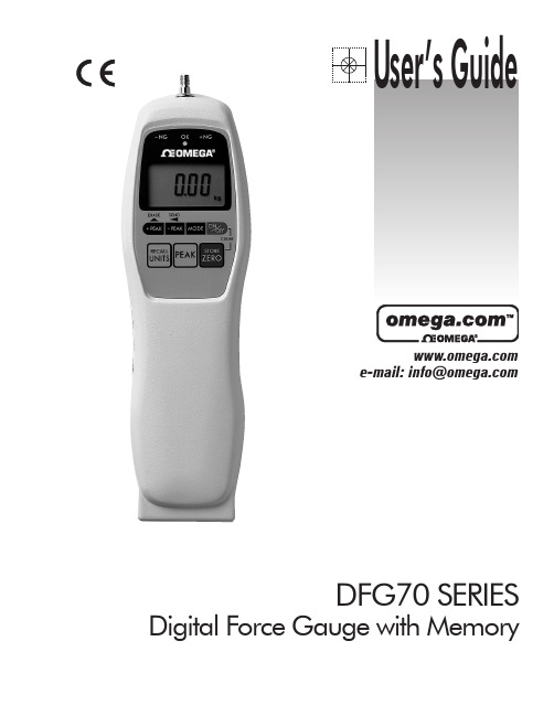
Omega DFG70系列数字力杆仪记忆型用户指南说明书
e-mail:**************DFG70 SERIESDigital Force Gauge with MemoryServicing North America:USA:One Omega Drive, Box 4047ISO 9001 CertifiedStamford, CT 06907-0047TEL: (203) 359-1660FAX: (203) 359-7700e-mail:**************Canada:976 BergarLaval (Quebec) H7L 5A1TEL: (514) 856-6928FAX: (514) 856-6886e-mail:****************For immediate technical or application assistance:USA and Canada:Sales Service: 1-800-826-6342 / 1-800-TC-OMEGA ®Customer Service: 1-800-622-2378 / 1-800-622-BEST ®Engineering Service: 1-800-872-9436 / 1-800-USA-WHEN ®TELEX: 996404 EASYLINK: 62968934 CABLE: OMEGA Mexico:TEL: (001) 800-826-6342FAX: (001) 203-359-7807En Espan ˜ol: (001) 203-359-7803e-mail:*******************************.mxServicing Europe:Benelux:Postbus 8034, 1180 LA Amstelveen, The Netherlands TEL: +31 (0)20 6418405FAX: +31 (0)20 6434643Toll Free in Benelux: 0800 0993344e-mail:************Czech Republic:Rudé armády 1868, 733 01 Karviná 8TEL: +420 (0)69 6311899FAX: +420 (0)69 6311114Toll Free in Czech Republic: 0800-1-66342e-mail:***************France:9, rue Denis Papin, 78190 Trappes TEL: +33 (0)130 621 400FAX: +33 (0)130 699 120Toll Free in France: 0800-4-06342e-mail:****************Germany/Austria:Daimlerstrasse 26, D-75392 Deckenpfronn, GermanyTEL: +49 (0)7056 3017FAX: +49 (0)7056 8540Toll Free in Germany: 0800 TC-OMEGA SMe-mail:*****************United Kingdom:One Omega Drive, River Bend Technology Centre ISO 9002 CertifiedNorthbank, Irlam, Manchester M44 5EX, EnglandTEL: +44 (0)161 777 6611FAX: +44 (0)161 777 6622Toll Free in England: 0800 488 488e-mail:**************.ukOMEGAnet SMOn-Line Service Internet e-mail http://***************************It is the policy of OMEGA to comply with all worldwide safety and EMC/EMI regulations thatapply. OMEGA is constantly pursuing certification of its products to the European New Approach Directives. OMEGA will add the CE mark to every appropriate device upon certification.The information contained in this document is believed to be correct but OMEGA Engineering, Inc. accepts no liability for any errors it contains, and reserves the right to alter specifications without notice.WARNING: These products are not designed for use in, and should not be used for, patient connected applications.INTRODUCTIONThe DFG70 is a highly sophisticated,laboratory grade digital force gauges which offer programmable high/low setpoints for go/no go testing.Store up to 256 values into memory,which can be displayed or transmitted using digimatic or serial output e the real mode to display load transients,or the peak mode to capture the peak force achieved during a test.Select measuring units between Pounds (ounces),Kilograms (grams) and Newtons.GENERAL OPERATION1Press .After a beep,the capacity of the gauge is displayed and the gauge will automatically enter into the measuring mode.Press and hold for at least four (4) seconds each time you wish to select between pounds (ounces),kilograms (grams) and Newtons.2HAND TIGHTEN (no tool!) selected attachment to the measuring shaft.3When the gauge is turned on,it will go directly to its real time measuring mode.Press to mea-sure peak forces.“Peak icon”on the display indicates peak measuring mode,whereas the peak read-ing will not change until a higher value is measured.To delete the last peak reading,press.To endpeak reading mode and go to real time measuring mode,press again.real time mode display peak mode display4If necessary,press to tare the weight of the attachment and shaft orientation.Pressingwill also clear the peak reading.5Make sure to apply tension and compression (-) forces to thegauge in line with the measuring shaft.DO NOT attempt to mea-sure forces perpendicular to the measuring shaft - damage to loadcell and/or shaft may result.PRECAUTIONS1.REGARDLESS of whether the unit is ON or OFF,DO NOT exceed the capacity of the gauge.At 110% of the rated capacity,the gauge beeps to warn.NEVER exceed 200% of the rated capacity,or the load cell will be damaged.2When mounting DFG70,use M4 mounting screws with a maximum insertion depth of 5 mm into the gauge.3Measure in line tension and compression forces only.DO NOT attempt to measure forces perpen-dicular to the measuring shaft - damage to load cell and/or shaft may result.4Hand tighten attachments only.DO NOT use tools.5Make sure this gauge and all peripherals are powered down before attaching any cables.6DO NOT disassemble the gauge.Disassembly voids warranty.LED’sWhen high-low set pointsare set, LED indicatesbelow (-NG), within (OK),or above set point value(+NG).PEAK iconWhen continuouslydisplayed, peak hold func-tion is activated. Whenflashing, indicates peakTENSION iconDisplayed for tensilemeasurements.BATTERY iconFlashes when the Ni-Cadcells need to be charged.+PEAKselects value of digit. When programming set points inmemory mode, deletes theFULL DUPLEXCOMMUNICATIONS PORT FORCE UNITSDisplays selected measur-ing units.POWERPress and release forON/OFF. When pressed and released in conjunction with the ZERO key, all values stored in memory will be deleted.MODEAllows operator to scroll through measuring mode, programming set points mode and peak memory mode.STORE/ZEROTares weight of attach-ment. Clears Peak reading. When pressed while turn-ing on gauge, deletes all readings stored in memory. In Peak memory mode, enters each value into stored memory.-PEAKRecalls -Peak value in peak mode. Also, used for shift-ing digits when program-ming set points. In peak memory mode, displays memory space left available or when connected down-loads digimatic data.MEMORY MODE1Press until “PEAK icon”flashes on the display.2Apply tension (-) or compression (+) forces,the display will hold the peak force mea-surement (peak reading will not change until a higher value is measured).3To store this value into memory,press .The value will be stored by a confirming beep and display will automatically reset to zero and is ready for the next measurement.4Repeat this sequence for each measurement to be stored up to 256 data.Note:to redo the last stored data,press .5To review the data stored in memory,press .Each stored data will be displayed,starting with the first value stored,each timeis pressed.When all stored data have been displayed,“END”will be appear on the display.To continue storing or recalling data again,press .Note:When is pressed after is pressed,the gauge will display remaining memory space.6To download data stored in memory,choose between the following methods:RS-232:Connect the gauge to the device receiving data by using CB-202 or CB-203 ethe R [CR] uppercase ASCII command to transmit data.(See page 8).7To delete all data stored in memory,press and release while holding.Two beeps will con-firm the memory reset.PROGRAMMING SETPOINTS MODE1Press until all numeric digits flash.2As High or Low points will be recognized automatically by gauge CPU,either High or Low may be set first.To set the 1st point (High or Low),press to select desired digit.Press to select the value of each selected digit.Scroll through each digit until the value desired has been defined.Once the 1st setpoint is selected,press so that all digits will be flashing.Then press in order to set 2nd point (High or Low).While all numbers are continuously flashing,press and repeat the above sequence to select the 2nd sepoint.Again all numbers will be flashing after the 2nd setpoint is set.While setting 1st and 2nd setpoints,tension (-) or compression (+) can be selected by pressing .3After 2nd setpoints are set and all numbers are flashing,press to review and scroll High or Low setpoint values.4Press twice and return to measuring mode.With High and Low setpoints set,whether on real time measuring mode or peak measuring mode,three LED’s above the display will light:-NG (Yellow LED) :for below Low setpoint OK (Green LED) :for between setpoints +NG (Red LED) :for above high setpoint(1) Beyond 256 data,“Full”will appear.(2)Stored data will be lost if battery voltage dropslower than normal.RS232 INTERFACE FUNCTIONS1RS-232C bi-directional interface functionsAll gauge functions can be duplicated from a remote location by utilizing RS-232C interface.All commands must be sent in upper-case ASCII character format followed by a carriage return (CR).RECHARGING NI-CAD BATTERY1To maximize the life of the battery,power will automatically shut off after 10 minutes of non-use.This automatic shut off feature can be bypassed and the gauge may be used continuously when the AC adapter/charger is used.2“BATT”icon will flash when gauge needs to be recharged.To maximize battery life,do not recharge until “BATT”icon flashes.With proper recharging,the battery can be recharged 500 times.3Push to turn off power.Then use the providedadapter/charger and plug into the correct AC output.It takes 8hours to charge fully.DO NOT recharge for more than 12hours.4When the gauge is turned off,make sure the AC adapter/charg-er is disconnected.COMMUNICATIONS PORTThe communications port is divided into three separate data formats.Pins one,two and five are assigned to the full duplex,RS-232C serial interface.Pins three and six represent the ±2VDC analog output and pins four,seven and eight provide cold-contact switching circuits to remotely hold and clear the display.PORT PIN DEFINITIONS 1 RS-232C Ground2 RS-232C Signal Output3 Analog Output ±2VDC4 External Switch Display Freeze5 RS-232C Receive Signal6 Analog Ground7 External Switch Zero/clear 8 External Switch CommonShowing DFG70modelShowing DFG70 modelSignal level:RS-232C Data bits:8 bits Stop bits: 1 bit Parity bits:NoBaud Rate:2400 bps* For example:to set 1000 (compression) as high: F1000[CR]to set 0500 (tension) as low: S-0500[CR]COMMAND FUNCTIONRESPONSEB [CR]Delete last data stored in memory R [CR] executed E [CR] errorC [CR]High/Low setpoint comparisonR [CR] OK U [CR] +NG L [CR] -NG E [CR] errorF±____[CR]*Select high setpoint R [CR] executed S±____[CR]*Select low setpointE [CR] errorH [CR]Recall +peak (compression)[value] [unit] P [CR] executed E [CR] errorU [CR] Recall -peak (tension)[value] [unit] P [CR] executed E [CR] errorI [CR] Clear Memory R [CR] executed E [CR] errorR [CR]Recall all memory data[value] [unit] M [CR][value] [unit] M [CR]R [CR] executed E [CR] errorW [CR]store data in memory R [CR] executed E [CR] errorD [CR]transmit display data[value][unit][mode][CR] executed E [CR] errorK [CR]select “Kg” units N [CR]select “N” units L [CR]select “lb” unitsO [CR]select “oz” units (only oz model)R [CR] executed P [CR]select peak mode E [CR] errorT [CR]select real time mode Z [CR]tare display Q [CR]turn off power2±2 VDC Analog SignalConnect the CB-101 analog cable to the full duplex port and the device receiving the data.3External Switch Display FreezeBy connecting (use contact closure and DO NOT apply voltage across) #4 and #8 of the communications port,the gauge instan-taneously captures the critical reading and holds the display from remote locations.[mode] = T: Real time, P: Peak [units] = K: Kg, N: Newtons, L: Pounds, O: Ounces5External Switch Display ClearBy connecting (use contact closure and DO NOT apply voltage across) #7 and #8 of the communications port,display may be cleared from remote locations.CAPACITY MODEL Pounds Grams Newtons OuncesKilograms DFG70-0.58.818 oz (0.001 oz)250.0 g (0.1 g) 2.450 N (0.001 N)DFG70-117.63 oz (0.01 oz)500.0 g (0.1 g)4.900 N (0.001 N)DFG70-4 4.410 lb (0.001 lb) 2.000 kg (0.001 kg)19.60 N (0.01 N)DFG70-1111.02 lb (0.01 lb)5.000 kg (0.001 kg)49.00 N (0.01 N)DFG70-4444.10 lb (0.01 lb)20.00 kg (0.01 kg)196.0 (0.1 N)DFG70-110110.2 lb (0.1 lb)50.00 kg (0.01 kg)490.0 N (0.1 N)DFG70-220220.4 lb (0.1 lb)100.0 kg (0.1 kg)979.0 N (0.1 N)Accuracy± 0.1% ± 1 LSD Display Update 20 updates/secondSelectable Units Displays values in grams/kilograms, ounces/pounds or newtonsOverload Capacity 200% full scalePowerFour internal AA Ni-Cad cells, eight hour capacity when fully charged with AC adapterLow Battery Indicator Display flashes BATT when battery is low CPU8-bit CMOSA/D Converter 16-bit Delta Sigma SystemMemoryNonvolatile, recall up to 256 measurements Peak Memory Recalls peak tension and compressionSetpoints Programmable high/low setpoints with color coded indicator.Dimensions9.6 x 2.9 x 1.2 in (245 x 73 x 30.5 mm)Ambient Temperature 32° to 100°F; 0 to 40°C Weight18 ounces Shipping Weight 4 poundsOutput PortsRS232C:Full duplex, 2400 baud, 8 data bits, no parity bit, 1stop bitAnalog:±2VDC full scaleIncluded AccessoriesAC adapter/charger; eight attachments: (3 hooks, flat tip, chisel tip, notched tip, conical tip, extension shaft) and hard-plastic carrying caseSPECIFICATIONSDFG70 RANGES (Resolution)DIMENSIONSDirect all warranty and repair requests/inquiries to the OMEGA Customer Service Department. BEFORE RETURNING ANY PRODUCT(S) TO OMEGA, PURCHAS ER MUS T OBTAIN AN AUTHORIZED RETURN (AR) NUMBER FROM OMEGA’S CUS TOMER S ERVICE DEPARTMENT (IN ORDER TO AVOID PROCESSING DELAYS). The assigned AR number should then be marked on the outside of the return package and on any correspondence.The purchaser is responsible for shipping charges, freight, insurance and proper packaging to prevent breakage in transit.FOR WARRANTY RETURNS, please have the following information available BEFORE contacting OMEGA:1.P.O. number under which the product wasPURCHASED,2.Model and serial number of the product underwarranty, and3.Repair instructions and/or specific problemsrelative to the product.FOR NON-WARRANTY REPAIRS,consult OMEGA for current repair charges. Have the following information available BEFORE contacting OMEGA: 1. P.O. number to cover the COSTof the repair,2.Model and serial number of product, and3.Repair instructions and/or specific problemsrelative to the product.OMEGA’s policy is to make running changes, not model changes, whenever an improvement is possible. This affords our customers the latest in technology and engineering.OMEGA is a registered trademark of OMEGA ENGINEERING, INC.© Copyright 1996 OMEGA ENGINEERING, INC. All rights reserved. This document may not be copied, photocopied, reproduced, translated, or reduced to any electronic medium or machine-readable form, in whole or in part, without prior written consent of OMEGA ENGINEERING, INC.Where Do I Find Everything I Need for Process Measurement and Control?OMEGA…Of Course!TEMPERATUREⅪߜThermocouple, RTD & Thermistor Probes, Connectors, Panels & AssembliesⅪߜWire: Thermocouple, RTD & ThermistorⅪߜCalibrators & Ice Point ReferencesⅪߜRecorders, Controllers & Process MonitorsⅪߜInfrared PyrometersPRESSURE, STRAIN AND FORCEⅪߜTransducers & Strain GaugesⅪߜLoad Cells & Pressure GaugesⅪߜDisplacement TransducersⅪߜInstrumentation & AccessoriesFLOW/LEVELⅪߜRotameters, Gas Mass Flowmeters & Flow ComputersⅪߜAir Velocity IndicatorsⅪߜTurbine/Paddlewheel SystemsⅪߜTotalizers & Batch ControllerspH/CONDUCTIVITYⅪߜpH Electrodes, Testers & AccessoriesⅪߜBenchtop/Laboratory MetersⅪߜControllers, Calibrators, Simulators & PumpsⅪߜIndustrial pH & Conductivity EquipmentDATA ACQUISITIONⅪߜData Acquisition & Engineering SoftwareⅪߜCommunications-Based Acquisition SystemsⅪߜPlug-in Cards for Apple, IBM & CompatiblesⅪߜDatalogging SystemsⅪߜRecorders, Printers & PlottersHEATERSⅪߜHeating CableⅪߜCartridge & Strip HeatersⅪߜImmersion & Band HeatersⅪߜFlexible HeatersⅪߜLaboratory HeatersENVIRONMENTALMONITORING AND CONTROLⅪߜMetering & Control InstrumentationⅪߜRefractometersⅪߜPumps & TubingⅪߜAir, Soil & Water MonitorsⅪߜIndustrial Water & Wastewater TreatmentⅪߜpH, Conductivity & Dissolved Oxygen InstrumentsM3514/1099。
SS4机车高压电器动作试验

三、主断路器试验。
1、闭合主断路器按键401SK,听主断闭合声音和主变压器交流声,看主断零压灯灭,辅助电压表显示上升至110V,合闸后应确认辅助电压,如低于310伏特,主变交流声不正常,应立即断电,降弓。
四、辅机起动试验
1、闭合劈相机按键404SK,另一手手扶400SK,听劈相机启动正常,看辅助电压表波动30-60伏特,劈相机灯亮又灭。注意:合主断、等辅助电压稳定后,在起劈相机,发现异常,立即断电。
牵引方法(同前)。
2、电阻试验,是风道继电器作用是,励磁电流不宜过大,200A左右即可,B节无加馈流。
3、试验正常后,两节电子柜开关重新恢复A组。
八、保护试验。
1、紧急制动,手轮离0,大闸非常位,此时主断应断开,列车管急剧降0.
2、自动停车。闭合自动信号开关,听警铃响7秒,紧急放风阀排风,主断跳闸。大闸置于重联位解锁,15秒后缓解,重新闭合主断。
机车高压电器动作试验。
准备工作。
1、低压试验良好,各机械、电器作用良好。
2、车顶作业隔离开关作业完毕,锁好车顶门。
3、各开关、塞门、闸刀处于正常位置。
4、AB节各室及地沟确认无人,无工具、杂物、锁闭各室门,落下锁闭。
5、人员齐全,均处于安全位置、操纵台无禁动牌。
6、总风压力700千帕以上,闸缸压力300千帕。
3、换向手柄打“制”位,闸缸压力缓解到100千帕,调速手轮离“0”到制动区,听91KM、92KM及线路杰出席吸合声,看主台“电制动”灯、“零位灯”、“预备灯”灭,励磁电流逐渐上升至930A,电机加馈电流上升至50A。注意闸缸压力不能降为0,以防加馈流,引起机车后溜。
4、断开406SK,听牵引风机1、2变压器风机,油泵停转,看“预备”灯亮,励磁电流、电机电流降为0.因560KA制位吸合,常闭触头打开,530KT又因风机关闭失电,预备电路被切断,正常后重新闭合406SK,看预备灯灭,励磁电流逐渐上升至930A,电机加馈电流上升至50A。
德劲两款高端收音机DE1102,DE1103印象
德劲两款⾼端收⾳机DE1102,DE1103印象曾经有⼀年左右的时间,我没有听cd机,因为我在玩fm收⾳机。
由于在指标上fm明显和cd不是⼀个档次,很多dx对fm不屑⼀顾。
我很怀疑他们有没有认真听过fm收⾳机。
同样的曲⽬,⽤cd机听到的声⾳是死的,⽽fm是活的,这是两者在感性上的差别。
当然要得到良好的收听效果,前提是有⼀台好收⾳机。
这⼀次介绍的收⾳机是两个:de1102,de1103。
它们是德劲⾼端系列“爱好者”中的两款。
1103先说1103的原因是这部收⾳机的亮点实在太多,给⼈很多惊喜,光芒完全盖过了1102。
1.外观第⼀眼看到1103,就被它的外观吸引。
少有的匀称⽐例以及和谐布局,简洁、贵⽓。
前⾯板镶嵌了⼀块经喷砂和氧化处理的银灰⾊铝板,和机⾝融合的很好,不说明你绝对看不出它是⾦属的。
⾯板上按钮⼩巧精致,超⼤的液晶屏差不多占了⾯板的⼀半。
⽆论是整体还是细节,都很耐看。
应该说实物⽐照⽚好看很多。
外壳的材质很好,并且模具开的很细⼼。
收⾳机握在⼿⾥沉甸甸的,机⾝和⼈⼿贴合,触感细腻。
2.接收性能。
⼀个收⾳机好与坏,接收性能说话。
1103接收性能在国内便携机中是佼佼者,并且和国外的⼀些中⾼档收⾳机相⽐也不会输,⽐如sony的7600gr――这是⼀些收⾳机玩家经过对⽐测试得出的结论。
1103的调频接收性能可以说是出类拔萃的。
我使⽤过多台收⾳机,包括买的和⾃⼰做的,调频接收性能都⽐不了1103。
有⼀年夏天,我沉溺于调频接收。
我⽤了⼀架⽺⾓天线,然后在收⾳机上加了⼀级带调谐的⾼放。
结果我收到了多⼀倍的调频电台,⽽且每个电台的⽴体声指⽰灯都能点亮。
噪声没有了,像被滤纸滤除了⼀样。
⽽这⼀次1103带给我的调频接收体验是颠覆性的。
我在阳台上⽤拉杆电线随意的接收,⼀会⼉就存了近50个调频电台。
我这⾥的调频资源是相对丰富⼀些,但是以前的话,收到30⼏个已经不错了。
1103使⽤双拉杆天线会是怎样⼀个境界?有时间要试⼀下。
小论德劲DE1103

小论德劲DE1103发布于:2016.11.24 - 21:18 |取了一个又一个的网名,复试半day累一头小汗.终于注册上来了!本人姓李居深圳通讯行业的干活,40岁,自幼有喜爱收音机恶习.上月父亲节想给成都老爹送一礼物,他也一老收音机迷.网上搜了一番,比较了一下电路及价格,逐买下一台DE1103,拿回家,以我这无线电准专家的眼手把玩一通,不错,德劲产品不错!国内收音机现能做到这水平,俺挺高兴,这一高兴就又跑了一趟,又买回一台1103,放心,不是给老爸寄台”备份机”,而是自用,虽然俺已有了一台sony7600GR和更高级的IC-R20.作为一位比较满意的顾客,我想对厂家最好的回馈不是去买“第三台DE1103”,而是提一些建议和用后感,所以就操起鼠标写几个字。
1)许多网评批驳DE1103的主要操作—音量调节不符合大众习惯,俺的看法正相反:由于音量调节本身的使用频度高以及国产电位器的质量低,个人认为DE1103主设计师这一改篡是合法合理合利的,请大胆坚持!这个改进对提高机器寿命有大补,而且使用一段后,会非常适应新调法2)二次变频非常正确!也是我从一开始就选取该款机的原因。
很多收音机爱好者认为二次变频仅仅是为了抗镜像,如果碰巧工作频点上方两倍中频处没有镜像(从广播米段划分来看,碰上镜像的概率还真是不高),那咱小日子不也过得好好的嘛?错!相信大部分收音机爱好者(甚至包括一些德生德劲工程师)都没有用过高档频谱仪(如HP8560),没有活生生地“看过”无线电波,把频谱仪分析带宽(RSW)打到100HZ(甚或更低的1HZ),你才知道,在这个时代,在我们生活的空间中,无线电波是多么的杂!多么的乱!那真叫一个“频花缭乱”。
罗嗦半day,还是用USA当代无线电大腕Cotter Sayre 一句话来总结:“对超外差接收机,镜像是一项最重要指标。
”是的!在21世纪这个频花缭乱的空间里,我们要抗的其实可能并不是真正稀有的镜像频率,而是在镜像带宽内出现的大量噪频,这些肥硕的基底躁声是永远存在的,不管你把旋钮拧到哪。
Extech GRT300 4线地电试验仪用户手册说明书

Manual del usuario Telurómetro de 4 hilos Modelo GRT300IntroducciónAgradecemos su compra del telurómetro de 4 hilos de Extech. El probador de tierra Modelo GRT300 se ha diseñado y probado conforme a las especificaciones de seguridad de la Publicación IEC 348, para los Aparatos de Medición Electrónica EN 61010-1, EN 61326-1, EN 61557-1, EN 61557-5 y otras normas de seguridad. El uso y cuidado adecuado de este medidor le proveerá muchos años de servicio confiable.Notas de seguridad•Lea cuidadosamente la siguiente información de seguridad antes de operar o dar servicio al medidor.•Use el medidor sólo como se especifica en este manual. De otra manera, la protección suministrada por el medidor puede ser afectada.•Condiciones ambientales nominales :Uso interior y exterior.Instalación Categoría IV 300V.Grado de contaminación 2.Altitud hasta 2000m.Humedad relativa 80% máx.Temperatura ambiente 0-40°C.Observe la simbología eléctrica internacional enlistada a continuación:El detector está completamente protegido con doble aislante o aislamiento reforzado.¡Advertencia! Riesgo de choque eléctrico.¡Precaución! Consulte este manual antes de usar el detector.Terminal de (masa) tierra.El equipo cumple las directivas vigentes de la Unión Europea.ADVERTENCIAPara evitar choque eléctrico, no toque las terminales durante las pruebasNunca aplique voltaje mayor a 300V a través de las terminales P1 y P2.Características•Controlado por microprocesador con características de seguridad avanzadas •Pantalla LCD de dos líneas• Escalaautomática•Pruebas de resistencia de tierra con cuatro escalas: 0-2Ω/0-20Ω/0-200Ω/0-2kΩ•Escala de medición de voltaje de tierra de 0-300VCA•Prueba automática para punta C.•Prueba automática para punta P.•Prueba de 2 hilos•Prueba de 3 hilos•Prueba de 4 hilos• Apagadoautomático•Retención de datos•Norma de seguridad: EN 61010-1 CATIV 300V, EN 61326-1Descripción del medidor1. TerminalC12. TerminalP1(Conexión de cable de prueba verde) 3. TerminalP24. TerminalC2(Conexión de cable de prueba rojo)5. Pantalla6. RcLED7. RpLED8. Botón 2 hilos9. Botón 3 hilos10. Botón 4 hilos11. Botón VCA12. Botón de encendido13. Botón PRUEBA/PARO 5 6 7OperaciónPrueba de voltaje de batería1. Presione de nuevo el botón "ON/OFF", si en pantalla aparece "Batería débil", reemplace lasbaterías.Medición de voltaje de tierra1. Conecte los cables de prueba como se indica enseguida.(1) Electrodo de tierra (varilla) a prueba (2) Punta de prueba2. Presione el botón "ON/OFF" y espere para “Seleccionar Función” en la pantalla.3. Presione el botón "ACV" y luego el botón "TEST/STOP".4. El voltaje de tierra se presenta en pantalla.Nota: Cuando el voltaje de tierra es mayor a 10V, pueden ocurrir errores en la medición deresistencia de tierra. Asegure que el valor indicado es menor a 10V.Medición de resistencia de tierraNota: El resultado medido puede ser influenciado por acoplamiento inductivo o capacitivo si los cables de prueba están torcidos o adyacentes uno al otro. Al conectar las sondas, mantenga separados los cables.ConfiguraciónInserte la punta de Potencial y la punta de Corriente (si se requiere) tan profundo como sea posible en el suelo. La distancia entre puntas debe ser entre 5 a 10 metros (16 a 32 pies)123 (1) Electrodo de tierra (varilla) a prueba (2) punta de Potencial (3) punta de Corriente123 (1) Electrodo de tierra (varilla) a prueba (2) punta de Potencial (3) punta de Corriente12 (1) Electrodo de tierra (varilla) a prueba (2) punta de PotencialPruebas1. Conecte los cables de prueba para pruebas de 2, 3 ó 4 terminales.2. Presione el botón ON/OFF y espere que abra la pantalla "Seleccionar Función"3. Presione el botón de la configuración "2P", "3P" ó "4P".4. Presione el botón "TEST/STOP" para comenzar la prueba.5. El medidor pitará durante la prueba (aproximadamente 10) y luego la lectura aparece en lalínea inferior de la pantalla.Notas:Indicadores LED "Rc" y "Rp":Rc: Sin salida de Corriente de prueba. Verifique las conexiones.Rp: Si Rp está activo y la pantalla indica "> 2 kΩ", la resistencia de tierra es mayor a 2000Ω.Si, en modo "4P", la pantalla indica "Vp Error", ponga en corto C1 (negro) y P1 (verde). Consideraciones sobre mediciónLas pruebas con 2 terminales son apropiadas para realizar la mayoría de las pruebas en suelos normalmente conductivos. Sin embargo, las mediciones de 2 terminales incluyen cable de pruebas y resistencia de contacto en la medición y el resultado será una lectura ligeramente más alta que la resistencia de tierra verdadera. Cuando los resultados medidos son mayores a lo deseado o si la directiva de medición requiere técnicas multiterminales, cambie a la técnica de 3 ó 4 terminales según sea necesario.Mantenimiento1. Tapa posterior2. Batería3. FusibleReemplazo del fusible 1.Desconecte los cables de prueba del instrumento. 2.Retire los dos tornillos para quitar la tapa. 3.Retire y reemplace el fusible con uno nuevo de igual valor y tamaño 0.1A/250V, 5 x 20mm. 4.Reemplace y asegure la tapa posterior.Reemplazo de la bateríaCuando en pantalla aparezca "Batería débil", reemplace las baterías.1.Desconecte los cables de prueba del instrumento y quite la tapa posterior y las baterías. 2.La batería está bajo el probador. 3.Reemplace con ocho baterías AA de 1.5V para lámpara, tenga cuidado de observar la polaridad correcta. 4.Reinstale el porta-baterías y la tapa.Limpieza y almacenamientoADVERTENCIA: Para evitar choque eléctrico o daño el medidor, no deje que entre agua dentro del estuche.Limpie periódicamente la caja con un paño húmedo y detergente, pero no use abrasivos o solventes. 123EspecificacionesEscalas de medición Resistencia de tierra: 0-2Ω, 0-20Ω, 0-200Ω, 0-2kΩVoltaje de tierra: 0-300V CA (40 a 500Hz) Precisión Resistencia de tierra: ±(2% lect.+3 dígitos)Voltaje de tierra: ±(2% lect.+3 dígitos)Resolución de resistencia de tierra 0-2Ω: 0.01Ω0-20Ω: 0.1Ω0-200Ω: 1 Ω0-2kΩ: 0.01kΩFrecuencia de prueba 820HzCorriente de prueba 2mATemperatura y Humedad Operación: 0 a 50°C (32 a 122°F) 80%R.H.Almacenamiento: -10 a 60°C (14 a 140°F)أ80%R.H.Fuente de tensión 1.5V (AA) x 8Dimensiones 250(L) x 190(W) x 110(D) mm (9.84x7.5x4.33”)Peso Aprox. 1430g (batería incluida)Fusible ( 0.1 A/250V 5 x 20mmCopyright © 2011 Extech Instruments Corporation (Una Empresa FLIR) Reservados todos los derechos, incluyendo el derecho de reproducción total o parcial en cualquier medio.。
浅析QJZ-300/1140隔爆兼本质安全型真空磁力启动器操作训练
压 熔 断 器 1 R 2 R 3 R 4 R C 插接 件 。主 腔 内 G D、 G D、 G D、 G D, A
顶 部 外壳 装 配 有 R C阻 容 吸收 器 。折 页 式芯 板 装 配 的正 面 有 本 安 变 压 器 , 导 组 件 X Z 近 控 远 控 选 择 开 关 )继 电 先 D ( , 器 组 J Z 1一 J , 绝 缘 板 设 有 : 流 桥 1 一 D、 控 单 机 D (J 5 )小 整 D4 程 选 择 开关 。熔 断 器 1 D 、 R 中 间继 电器 2 J、Z , 护 R 2 D, Z 3J 保
电 , 证 用 电安 全 。主腔 内右 侧外 壳 装 配有 真 空 隔 离换 向 保
Q Z 3 01 4 J 一 0 /10正 反 转 控 制操 作 和停 电送 电操 作 , 必 就
现 制造技 与 代 术 装备
须 掌握 其 工 作 原理 , 看 图 , 画 图 。 会 会
2 1工 作 原 理 .
向 手 柄设 有 机 械 闭 锁 ,只有 按 下停 机 按 钮 才 能 转 动 真 空
隔 离换 向 手柄 。 其作 用 是 换 向开 关 与 真 空 交 流 接 触 器 的
钮 , 的 能转 动 换 向 手 柄 ; 向 开 关 闭 合 到 位 , 机 按 钮 才 换 停 才 能 弹 出 。 换 向开 关 和 前 门 的闭 锁 的操 作方 法 是 将 手 柄
锁 、 空 管漏 气 闭锁故 障显 示及 电源 和 运行 显 示 。如 何快 真
速 的 培 训 郑 煤 集 团 在 职 职 工 和 学 院 学 生 掌 握 Q Z 3 014 J 一 0 /10隔 爆 兼本 质 安 全 型真 空 磁 力启 动 器 ?我 浅谈
一
德劲DE1103VS德生PL350
龙源期刊网
德劲DE1103VS德生PL350
作者:王雷
来源:《电子世界》2005年第08期
互联网、数字电视等多媒体技术的飞速发展给这个世界带来比以往任何时候更加多彩的资讯和娱乐享受,而作为传统信息媒体的广播业却正经受着前所未有的挑战,这一变化也对收音机的制造业造成了冲击。
由于成本和市场的原因,作为收音机制造巨头的SONY和GRUNDIG 已逐渐停止了中高档收音机的研发和生产,而留下的空白正迅速被德生和德劲这两大国内中高档收音机制造商所填补,作为德生便携机的高端机型PL350和德劲爱好者系列的高端机型
DE1103,正是本篇文章要介绍的重点。
JBT 11101-2011 齿条千斤顶
下列术语和定义适用于本标准。
2.1 主载荷位置 load point 千斤顶额定起重量载荷加载的位置。一般指顶升件顶部的托盘(以下简称托盘)。
2.2 额定起重量(Gn) rated load 正常工作条件下,在主载荷位置加载时,千斤顶能承受的最大设计质量。
I
标准分享网 免费下载
JB/T 11101—2011
前言
本标准由中国机械工业联合会提出。 本标准由全国起重机械标准化技术委员会(SAC/TC227)归口。 本标准负责起草单位:杭州锦昌起重机械有限公司。 本标准参加起草单位:杭州四达机械电子有限公司。 本标准主要起草人:黄振远、周云飞、崔振元。 本标准为首次发布。
II 标准分享网 免费下载
JB/T 11101—2011
齿条千斤顶
1 范围
本标准规定了齿条千斤顶的术语和定义、型式和基本参数、要求、试验方法、检验规则以及标志、 包装和贮存。
本标准适用于矿山、桥梁、铁路、建筑等行业使用的机械式齿条千斤顶(以下简称千斤顶)。
2 术语和定义
ICS 53.020.99 J 源自0 备案号:33629—2011中华人民共和国机械行业标准
JB/T 11101—2011
代替 JB/T 7—1993
齿条千斤顶
Rack and pinion jacks
2011-08-15 发布
2011-11-01 实施
- 1、下载文档前请自行甄别文档内容的完整性,平台不提供额外的编辑、内容补充、找答案等附加服务。
- 2、"仅部分预览"的文档,不可在线预览部分如存在完整性等问题,可反馈申请退款(可完整预览的文档不适用该条件!)。
- 3、如文档侵犯您的权益,请联系客服反馈,我们会尽快为您处理(人工客服工作时间:9:00-18:30)。
他山之石可以攻玉——德劲DE1103终极摩机实验作者:作者:Ir…文章来源:作者:Iris, www.radioscanner.ru 翻译:kmzkdd 点击数:6421 更新时间:2006-5-8文章的想法是在我第一篇短评发表之后不久出现的,随后几个月里进行了修改。
这段时间里很多“无线电扫描”网站的网友购买了收音机,并且在论坛上。
与此同时,我也收到了许多DE1103用户的来信以及他们的评价。
德劲 DE1103具备许多优秀的品质,其实它还可以表现得更好。
从第一天使用这台收音机开始这个信念就一直伴随着我。
时间证明DE1103不仅是个好产品陷。
的目的——对我们的讨论做一个总结并且发布改善DE1103性能的摩机实验。
通过不算太复杂的实验,在您的手中将会是另一部“新的”收音机。
虽然外3,但是它已经摆脱了“儿科病”,使用起来变得更好、更方便了。
方便重复试验步骤,我尽量努力做到最大限度的简单可行。
文章中有详细的改装说明。
为了完成这项工作需要准备一些不贵的元件和普通的工具。
但是,我需要“外科手术”般的精细操作,所以对那些不懂技术或者没有把握完成以下操作的人,我劝告保持收音机现有的工作状态或者把这件事情委托给有经验的警告:作者不承担读者在独自重复以下实验操作时,由于可能发生的危险而损坏收音机的责任。
理解这篇文章之前先别急于下手!103的主要缺陷:节不便。
路的噪音与不稳定性,人体感应的敏感性。
步进频率设置。
像频道接收能力不高(按专业水准)。
敏度下降(在短波波段)。
项缺陷使收音机伴随着时间的流逝而渐渐失掉了自己的实用性。
虽然 DE1103耗电高于平均水平,但是还可以接受。
甚至使用随机提供的1300mA充电电个小时。
带充电功能也是其优点之一。
对于那些使用容量超过2000mA充电电池的用户来说,可以进一步减少电池寿命短带来的问题。
句关于充电电池的话。
正如有经验的用户所证实的,好处之一是随包装提供的德劲牌容量1300mA充电电池。
这些充电电池在收音机中工作正常,它们的量接近。
息说所购买的收音机随机提供的充电电池质量较差,个别打着“Delay 4WD”的商标。
这种电池不可靠,有的从购买的第一天起就不能用了。
中波波段频率步进不能设置为9 KHz,短波不能设置为5 KHz,调谐很不方便。
使用一般的方法自己是无法改变的,剩下的就只有习惯它了,在搜索和设留心观察显示屏显示的频率数字。
的设计师所没完善的地方,我们可以尝试着靠自己的力量来改变。
开始我就惊讶于我的 DE1103使用外接天线接收时的稳定性。
德劲 DE1103短波波段强信号的接收能力已经远远超过了自己的竞争者。
我所没有料到的是,收音机会产生信号过载的现象,哪怕是只用简单的天线插入天线接口。
那时,这些意见使我困惑了,而且负面的评述一直持续到现在。
消息令人不快,因的过载稳定性使我下决心为有经验的用户解决这个问题,从一般级别到推荐改造范围,从而找到一款既好又不贵,在家中或者旅途中使用的收音机。
我的从头开始”以及厂家做了“不见得如此”的推论不久前得到了完全的证实。
拆开论坛朋友为我提供的一台新版DE1103后证实了我的推测。
德劲人已经改保留了它的的外观,如我2004年所购买的这台。
新版型号大约在2004年十月份出现。
德劲 DE1103确实存在短波波段强信号过载的现象。
这个令人不快的事实不得不让我在 DE1103缺陷的目录中又增加了一项——使用外接天线过载。
DE1103外观上没有变化,仔细观察发现新品只是前面板粘贴了圆形的带字母“CNR”的标贴。
个标贴的几乎都是新版DE1103,但是标贴(包括缺少标贴)也许只是收音机版本的间接标志而已。
认您的收音机是哪个版本,可以打开FM波段调谐到任意一个电台,把直径3.5 mm的空插头插入天线接口。
收音机当您插入空插头时拉杆天线在FM波段总是断开的,所以此时FM台接收效果应该下降或者完全消失。
要验证这个现象最好是调谐到一个弱信号F 头时,可能由于通过接口触点电容“渗漏”的强信号而没有注意到这个差别。
如果插上空插头后证实存在差别,那您的就是新版 DE1103——但是,也别除了外接天线过载),新版并不比旧版的差。
为了修正这个缺陷,返回到以前更有效的外接天线电路状态,您需要准备添加两个电容。
的步骤被分为几个篇章,每部分以独立的改装工作相连。
一些改装具备推荐的特性,为了修正厂家存在的失误它们是必须做的,我建议改装它们。
篇章名的文字给与标出。
其余的改装改善效果不是很明显,由用户本着“挖掘最大潜力”的愿望来决定。
但是不管怎样,您的劳动必将为您的收听工作带来更现果的奖励。
第一部分是为那些第一次打算拆解自己收音机的用户。
下面是拆解 DE1103的详细说明。
对于已经会拆解收音机的可以立即转入下一篇章。
朝下把收音机放在桌子上,从电池仓中取出电池。
拧出7颗螺丝,在机壳后面板被箭头标出。
别忘记位于电池仓中的固定螺丝。
别拧用于固定拉杆天线的那机身周边仔细的从中部接缝处分开前、后部分机壳,先从底部开始再沿两侧。
部机壳结合得比较紧密,要用点儿力才能完全分开。
部分机壳本身与第三部分连接在一起。
半部机壳电路板接线插座上取下白色的扁线电缆,捏住扁线接头后面部位,慢慢的向外拔出它。
线座上拔出来自飞梭调节轮的导线。
两半机壳只由扬声器导线连接,从扬声器接点上焊下导线。
机前面板部分(带显示屏和按键)向外放置,可以见到因摩机触动的印刷线路。
路板上连接焊脚处焊开磁棒天线的引线和拉杆天线的导线。
为了避免组装时出现错误,建议开始时先画下来厂家磁棒天线的导线连接。
路板上焊开通向飞梭调谐轮的橙色导线。
从内向机壳后盖紧固电路板的小螺丝,抬起电路板,先从左侧方向(有外接天线、耳机和外接电源插孔)。
抬起电路板时遇到磁棒天线的阻碍,可以拧下天线杆右侧的紧固件,再把天线向上移一点。
,从机壳后盖中提出右部分电路板(安装有飞梭调谐轮)。
外接天线接头(*推荐——只限于新版)两片带引线的微型陶瓷电容33…150 nF (0,033 – 0,15 μF)。
片所示位置,剪断该处两条印刷导线。
去掉电路中的电容С1。
处电路板焊上电容,用导线连接电路板上部边缘的两条相邻导线,如照片所示。
(注:Перемычка——跨接线)再接上外接天线时,拉杆天线的前置放大器将被断开,收音机不再过载。
频率合成器(*建议)两个容量15 nF (0,015 μF)的瓷片电容,最好是 SMD(为了表面安装)。
nF电容换掉电容С404(旁边是频率合成器集成电路)。
干净一小段印刷导线,通向二本振荡器屏蔽后盖底部(见照片),再与电路板“地线”之间焊上15 nF电容。
改装后,使用飞梭调谐时不会再发出原有的杂音和喀呖声。
短波调谐时无噪音。
,要想彻底摆脱PLL电路噪音和自激只有依靠屏蔽(见“屏蔽”篇)。
长波-中波-短波单元的输入滤波器将提高收音机在15 MHz频率以上灵敏度。
原来的输入滤波器在高于12 MHz时会产生渐进性的“阻塞”。
由于这个原因,短波波段高频区域的灵敏度会产笔者根据收听使用经验推断,在接收低于20MHz频率信号时完全可以消除这个缺陷。
这样在使用拉杆天线时,电路中前置放大器开始工作,此时DE1103端。
输入滤波器是我认为的“扩展计划”,首先推荐给那些使用外接天线接收短波高频波段的爱好者,以及那些为 DE1103灵敏度衰落而苦恼的用户。
同时可以频遏制镜像频道的能力(见测量结果)。
除此之外,这个改装后滤波器可以提高30MHz以上频带的灵敏度,具体的将在后面谈到。
瓷片电容:个,个,个(最好是 SMD),2 个(最好是 SMD)。
电感为330nH (0,33μH)小型高频扼流线圈2个。
片所示位置剪断信号电路板上的印刷线路,线路打磨干净并挂锡。
nH高频扼流线圈换掉电感L105(在照片上部),并在剪断的线路位置焊上第二个330nH高频扼流线圈。
并联这个电感再焊上一个15pF电容(在照片上它。
F换掉电容С132,130 pF换С135。
滤波器电路上增加一个5,6pF电容,如照片所示,在新位置上还有一个130pF电容(在照片下部)。
缺少一个容量130pF的电容,每次我不得不从这些电容中用并联的两个总容量为130pF的电容(见照片上部分)替换。
器到极致:的幅频特性…:水平10MHz,垂直10dB。
新滤波器详细的特性将在后面谈到,在测量篇。
音量控制和SSB方式下的频率微调使用单边带微调钮FINE来控制音量,而SSB方式下的微调将由飞梭调谐轮经过按压 VOL键实现。
:一只小功率阻抗为3,3KΩ电阻(可以是3,0KΩ或者3,6KΩ),带绝缘的细连接导线(型号KMZK等)。
片所示位置,在电路板正面剪断印刷导线。
路板背面用长度75mm导线连接电阻R706左侧引线;导线另一头从上往右侧连接,如下面照片所示。
电路中的电阻 R514(在“VOL”标志焊脚的左下方)。
度90mm导线连接微调旋钮FINE下端输出,如照片所示(连接“А”),微调旋钮FINE中端输出经过3,0-3,6KΩ电阻与焊脚“VOL”相连(连接“B”),电阻置于导线断开处,两条导线之间距离15mm和65mm。
种连接方法就简单多了。
直接在微调旋钮中端输出焊上添加电阻,另一头经过长度70…75mm导线与点“VOL”连接。
路板上用碾粘带或者快干胶把导线固定起来。
借助单边带微调钮FINE可以实现令人更习惯的音量调节方式,而SSB方式下微调第三本振可用飞梭调谐轮通过按压VOL键来实现(参照厂家音量调节方显示屏上显示的数字音量电平与第三本振相对解谐频率相符。
改装用的这台收音机,与调谐第三本振的关系如下(以步进调谐方式测量了波段几个点):--------------------------------------------------------------平VOL 解谐相对中频接收- 1860- 1285- 717- 150+ 470+ 1168+ 1562+ 1622---------------------------------------------------------------台收音机调谐波段的边缘数值可能与上述例子不同,而总的波段谐调位于3,2…3,5KHz范围之内。
这样,在64级调节水平情况下平均一步调谐大约是50线控制不是一直有效的,在调谐波段边缘附近由60Hz到30Hz变化。
中心调谐位于30…34水平区域,具体由每台收音机的第三本振参数决定。
本振的频率稳定性非常好——在电路中使用了带电子“扩展”的变容二极管谐振器。
改装后,可以使用原来的定时功能按精确预置的频率接收SSB电台。
还记得吗?厂家方式下可以设置时间及接收方式开启收音机在最后调谐频率(或存储音量和60分钟定时。
在这种自动开机的情况下SSB接收方式有可能出问题,存在破坏预先通过微调旋钮FINE精确调谐所设置的频率的可能性。
