摩托罗拉电话机说明书ct50
2003年Motorola公司产品说明书

MANUAL REVISION12/3/03© Motorola, Inc. 2003.8000 W. Sunrise Blvd., Ft. Lauderdale, FL 33322Printed in U. S. A.This revision outlines changes that have occurred since the printing of your manual. Use this information to supplement your manual. REVISION CHANGE:Page Section No.Section Title Paragraph Descriptioniv Table of Contents2.6 and 6.2Asterisk deleted from section headings.1-2 1.2Introduction: Siren/PA DescriptionTable 1-1Asterisks deleted from rows 3 and 11 of table 1-1.2-22.2Operation: Public Address OperationTable 2-1Replaced ‘Wail’ with ‘Yelp’ in Hi-Lo Selected Tone row of table 2-1.2-3 2.6 Operation: Ex t ernal RadioOperation 2.6Deleted asterisk from section heading and deleted first line of text.5-25CPS ProgrammingTable 5.2Deleted asterisk from Manual Tone cell (row 2) and deleted table note.6-46.2Installation, Disassembly, and Assembly: Horn-Ring Transfer Relay6.2Deleted asterisk from section heading and deleted first line of text.6881096C46-OMCS 2000 Mobile RadioInstallation Manual*FMR-2051-1*FMR-2051-1This Page Intentionally Left BlankTable of Contents Foreword.................................................................................................... F-ii Product Safety and RF Exposure Compliance.......................................................................................F-ii Manual Revisions................................................................................................................................... F-ii Computer Software Copyrights.............................................................................................................. F-ii Document Copyrights............................................................................................................................. F-ii Disclaimer............................................................................................................................................... F-ii Trademarks............................................................................................................................................ F-iiList of Figures (v)List of Tables (vi)Chapter 1Introduction.........................................................................1-11.1Notations Used in This Manual......................................................................................................1-11.2Siren P/A Description.....................................................................................................................1-11.3Cabling Diagram............................................................................................................................1-4Chapter 2Operation.............................................................................2-12.1Siren/PA Operation........................................................................................................................2-12.1.1Control Unit.......................................................................................................................2-12.2Public Address Operation..............................................................................................................2-22.2.1Control Head/DEK-Plus....................................................................................................2-22.3Siren Tone Operation....................................................................................................................2-22.3.1Control Head/DEK-Plus....................................................................................................2-22.4External Radio Operation..............................................................................................................2-32.4.1Control Head/DEK-Plus....................................................................................................2-32.5Airhorn Operation..........................................................................................................................2-32.6Manual Operation..........................................................................................................................2-32.7Speaker Protection Alert................................................................................................................2-32.8Power-Up Feature.........................................................................................................................2-42.8.1Siren State........................................................................................................................2-42.8.2DEK-Plus..........................................................................................................................2-4Chapter 3Theory of Operation............................................................3-13.1Overview........................................................................................................................................3-13.2Microprocessor and Control Interface............................................................................................3-13.2.1Bus Interface.....................................................................................................................3-13.3Low-Level Audio............................................................................................................................3-23.4High-Level Audio...........................................................................................................................3-2iv Table of Contents3.5Power.............................................................................................................................................3-33.6Power Control and Speaker Short Detection.................................................................................3-3 Chapter 4Configuration/Programming of the Siren/PA...................4-1 Chapter 5CPS Programming..............................................................5-1 Chapter 6Installation, Disassembly, and Assembly.........................6-16.1Cables............................................................................................................................................6-26.2Horn-Ring Transfer Relay..............................................................................................................6-46.3Disassembly and Assembly...........................................................................................................6-46.3.1Disassembly......................................................................................................................6-46.3.2Assembly..........................................................................................................................6-56.4Pushbutton Removal and Replacement........................................................................................6-5 Chapter 7Maintenance and Troubleshooting....................................7-17.1Overview........................................................................................................................................7-17.2Maintenance..................................................................................................................................7-17.2.1Public Address Input Sensitivity Test................................................................................7-17.2.2Frequency Response Test................................................................................................7-17.2.3Siren Output Power Test...................................................................................................7-17.2.5Speaker Short Circuit Protection Test...............................................................................7-27.2.6Operating Mode Retention Test*......................................................................................7-27.2.7Version Display in Test Mode...........................................................................................7-2 Chapter 8Siren/PA Schematics and Mechanical Drawings.............8-1 Appendix A Replacement Parts Ordering..............................................A-1A.1Basic Ordering Information............................................................................................................A-1A.2Motorola Online..............................................................................................................................A-1A.3Mail Orders....................................................................................................................................A-1A.4Telephone Orders..........................................................................................................................A-2A.5Fax Orders.....................................................................................................................................A-2A.6Parts Identification.........................................................................................................................A-2A.7Product Customer Service.............................................................................................................A-2 Index..............................................................................................................I-iDecember 2, 20036881096C46-OChapter 1Introduction1.1Notations Used in This ManualThroughout the text in this publication, you will notice the use of note, caution, warning, and danger notations. These notations are used to emphasize that safety hazards exist, and due care must be taken and observed.NOTE:An operational procedure, practice, or condition that is essential to emphasize.1.2Siren P/A DescriptionThe MCS 2000 Siren/PA is an external accessory that generates siren tones and amplifies audiosignals from the radio for public address (PA). It can deliver 65, 75, or 100 watts of siren power to an11 ohm speaker, or 130 watts to dual 11 ohm speakers. In the PA mode, it can deliver 50 watts ofaudio power.This accessory consists of the Siren/PA unit and the cables that connect the Siren/PA to your MCS 2000 radio system.The Siren/PA unit is usually located in the cargo area of a vehicle. It can be operated using one of the following:•Mobile radio control head•Direct Entry Keyboard (DEK-Plus).1-2Introduction: Siren P/A Description Some Siren/PA features can be programmed by a qualified radio technician using the CustomerProgramming Software (CPS). A summary of available features for each Siren/PA configuration isshown in Table 1-1.Table 1-1. Siren/PA FeaturesFeature Using the Control Head Using the DEK-Plus Wail/Yelp/Hi-lo tones Yes Yes“Airhorn” tone Yes YesSiren manual tones No NoPublic address Yes YesExternal radio Yes YesPA volume control Yes YesSiren power control Automatic AutomaticSpeaker short protection Yes YesYes YesProgrammable parameters(using the radio codeplug)Power-up self check Yes YesHorn-Ring override No NoSiren State retained (while radio off)No*No** Not available in initial offering.December 2, 20036881096C46-OChapter 2Operation2.1Siren/PA Operation2.1.1Control UnitDepending on the installed configuration, the Siren/PA may be controlled by buttons on the control head or on the DEK-Plus.Figure 2-1: Model III Control Head with Siren/PA FunctionsFigure 2-2: Direct Entry Keyboard (DEK-Plus)2-2Operation: Public Address Operation2.2Public Address OperationThe Public Address feature amplifies and broadcasts the user's voice over the siren speaker.2.2.1Control Head/DEK-PlusTo activate the Public Address function, momentarily press the PA button. The corresponding light-emitting diode (LED) will light up and the PA feature will be activated.The control head display will temporarily show the current PA volume setting. To set the PA volume, rotate the radio's volume control (the rotary knob on the control head).NOTE:If you adjust the PA volume with the rotary knob on the control head, it will change the radio's volume setting based on the position of the knob.To use the Public Address feature, press the Push-To-Talk (PTT) button and speak into themicrophone. Your voice will be amplified and broadcast over the siren speaker.NOTE:The PTT button cannot be used to transmit while the PA feature is activated.If the Public Address and Siren options are both activated, the Siren function will be overridden when the PTT is pressed. The Public Address feature will have priority, and any siren tone or incomingradio signals (if in External Radio mode) will be abruptly muted.To turn off the Public Address, momentarily press the PA button again.2.3Siren Tone OperationWail, Yelp and Hi-Lo siren tones are broadcasted over the siren speaker. Use the Siren function to toggle between siren tones when broadcasting.2.3.1Control Head/DEK-PlusTo turn on the Siren function, press the Siren button momentarily. Then press the Wail, Yelp, or Hi-Lo buttons to broadcast the desired tone. The corresponding LEDs light up and the control headdisplay temporarily shows the selected siren tone.Any time the siren tone is changed, the display will briefly show the newly selected tone (even if the Siren function is off). To change the tone, press the Siren button on the DEK-Plus or Sirn button on the control head momentarily.If the Horn-Ring accessory is connected, you can change the siren tone by pressing the vehicle’sHorn-Ring while broadcasting a siren tone. (The operation of the Horn-Ring feature is shown inTable 2-1.)NOTE:You can change the siren tone at any time. The Siren function does not have to be activated.Table 2-1. Horn-Ring OperationSelectedChanges to NoteToneWail Yelp Press and release the Horn-Ring to change to Yelp tone. Press theHorn-Ring again to return to Wail tone.Yelp Airhorn Press the Horn-Ring to create the Airhorn tone. Airhorn sounds aslong as the Horn-Ring is pressed. Release the Horn-Ring to returnto Yelp tone.Hi-Lo Yelp Press and release the Horn-Ring to change to Yelp tone. Press theHorn-Ring again to return to Hi-Lo tone.December 2, 20036881096C46-OOperation: External Radio Operation2-32.4External Radio OperationThe External Radio feature amplifies and broadcasts incoming radio messages over the sirenspeaker, allowing radio communications to be heard outside the vehicle.2.4.1Control Head/DEK-PlusTo enable the External Radio feature, turn the Siren function on by momentarily pressing the Siren button on the DEK-Plus or the Sirn button on the control head. Then, select the External Radiofunction by pressing the Ex Rd button. The corresponding LEDs will illuminate.To adjust the External Radio volume, turn the volume control (rotary knob) on the control head.To turn off the External Radio feature, press the Siren button on the DEK-Plus or the Sirn button on the control head again, or select a different Siren function (Wail, Yelp, etc...). Once you turn off the External Radio function, the radio's receive volume will correspond with the position of the rotaryknob on the control head.2.5Airhorn OperationThe Airhorn feature—available with the Control Head and DEK-Plus configurations—broadcasts an airhorn tone over the Siren speaker. To broadcast the Airhorn, momentarily press the Ar Hn button.To turn off the Airhorn, press the Ar Hn button again.2.6Manual OperationThe Manual function—available with the Control Head and DEK-Plus configurations—allows theHorn-Ring to activate a siren tone.To enable the siren tone to be generated via the Horn-Ring, press the Man and Siren buttons. The corresponding LEDs will illuminate. Press the Horn-Ring to broadcast the pre-set tone (tones areprogrammed in the CPS, the default tone is “Wail”). You can program the Horn-Ring to generate the following tones:•Manual Wail: Pressing the Horn-Ring activates a rising Wail that peaks at 1500 Hz andcontinues as long as the Horn-Ring is held. When you release the Horn-Ring, the Wail tonefalls until the tone is muted.•Manual Yelp: Pressing the Horn-Ring activates a Yelp tone that continues as long as the Horn-Ring is held. When you release the Horn-Ring, the tone immediately mutes.•Manual Airhorn: Pressing the Horn-Ring activates an airhorn sound that continues as long asthe Horn-Ring is held. When you release the Horn-Ring, the tone immediately mutes.2.7Speaker Protection AlertWhen a short exists, the system performs a routine to “protect” itself from further harm. If a speaker short occurs, any audio broadcast (Siren functions, PA audio) is terminated. The Control Headdisplays SPKR SHORT. When the problem is corrected, the Siren/PA returns to its previous operation.6881096C46-O December 2, 20032-4Operation: Power-Up Feature 2.8Power-Up Feature2.8.1Siren StateThe Siren/PA Accessory powers up in one of two ways:•Warm Start (battery power was not removed)•Cold Start (battery power was removed).2.8.2DEK-PlusIn a Warm Start with a DEK-Plus, the Siren will power up with the PA Volume, the siren tone, and the Siren On/Off in their previously selected state at power-down, and with the PA off.NOTE:In a Warm Start with the DEK-Plus, the CPS may be used to program whether or not the Siren ON/OFF powers up in its previous state. This feature can be disabled, causing the Siren/PAto always power up with the Siren off.In a Cold Start, with a DEK-Plus, the Siren will power up with the default PA Volume, the Wail tone, the PA off, and the Siren off.December 2, 20036881096C46-OChapter 5CPS ProgrammingThe Customer Programming Software (CPS) stores programmed options in the radio’s codeplug.The CPS is preprogrammed with default settings at the factory, but it may be modified to suit yourneeds. There is one primary screen in the CPS for editing the Siren/PA options. To access thisscreen, double-click the “Radio Wide” tab shown in Figure 5-1.Figure 5-1: “Tree View” Screen ShotUnder the “Siren Operation” field, the “Siren/PA” option must be selected in order to modify the unit’s CPS options. Selecting the “PA Only” option will only allow you to modify the Public Address options.Figure 5-2: “Siren/PA Options” Screen Shot5-2CPS Programming: The Siren/PA Options screen enables you to modify various Siren/PA options (default settings areindicated). The following tables describe the programmable fields and their settings:Table 5-1. Public Address FieldsField OptionsOptions Audio Muting Disabled (default): Routes all audio to the Public Address speaker when inExternal Radio Mode.Enabled: Prevents deciphered SECURENET® audio and Mobile VoiceStorage message playback from being heard over the external speaker.PA Ignition Sense Disabled (default): Public Address operable with ignition switch on or off.Enabled: Public Address operable only with ignition switch on.Ext Radio Ignition Disabled (default): External Radio operable with ignition switch on or off.Enabled: External Radio operable only with ignition switch on.Default PA Volume Level This field is programmed to set the Public Address volume level for initialpower-up. If no volume level is manually selected by the operator, thevolume will default to the setting in this field.The range is from 0 to 15 (default 11).Siren P/A After Reset LAST STATE* (default): The siren will power up in the same state, on or off,as at power-down (Warm Start).Off: Siren will always be off at power-up.*Not available in initial offering. See Table1-1, “Siren/PA Features,” on page1-2.Table 5-2. Siren FieldsField OptionsHi-Lo Airhorn Tones Disabled: Hi-Lo and Airhorn tones cannot be produced.Enabled (default): Hi-Lo and/or Airhorn tones are allowed.Manual Tone This field selects the Manual Tone that will be heard when the Horn-Ring ispressed. The choices are Ar Hn, Wail, or Yelp (default is Wail).Siren Ignition Sense Disabled: Siren tones operable with the ignition switch on or off.Enabled (default): Siren tones operable with ignition switch on.December 2, 20036881096C46-OInstallation, Disassembly, and Assembly: Cables6-34.Route the red power cable to the vicinity of the battery positive terminal. Be careful to avoidareas where the cable might be subjected to abrasion or high temperatures, and use rubbergrommets wherever the cable passes through a bulkhead, such as the firewall.5.Locate the fuse holder as close to the battery as possible and away from any hot enginecomponents.a.Mount the fuse holder using the provided mounting hole and dress wires as necessary.b.Connect the fuse holder red adaptor lead plug to the mating receptacle on the red powercable of the Siren/PA unit (see Figure 6-3).6.Connect the power cable red lead from the fuse holder to the positive (+) battery terminal.7.Plug fuse into in-line fuse holder (see Figure 6-3).Figure 6-3: Power Cable Assembly8.Route the radio cable to the radio. Observe that the radio has two connectors on its frontpanel. The radio control head should be connected to the left connector, and the Siren/PAshould be connected to the right connector, facing the radio. (See Figure 6-2.)9.(a)Control unit cable—for units using a DEK-Plus:•In the Dash Mount Configuration, the HKN6137 (MCS 2000, 4 ft. DEK-Plus) cable isused.•In the Remote Mount Configuration, the HKN6136 (MCS 2000, 17 ft. DEK-Plus) cableis needed.(b)When the Siren/PA is controlled from the radio, no control unit connection is supplied. 6881096C46-O December 2, 20036-4Installation, Disassembly, and Assembly: Horn-Ring Transfer Relay6.2Horn-Ring Transfer RelayIn order to make Siren operation more convenient under emergency conditions, the vehicle’s Horn-Ring (or buttons) can be used to control siren functions (refer to Chapter 2 on page 2-2). Thisconvenience allows the driver to concentrate on the road and traffic conditions.Figure 6-4 shows wiring diagrams for connecting the Horn-Ring via a transfer relay for both negative and positive ground systems. As an alternative, a simple momentary contact pushbutton (normallyFigure 6-4: Siren/PA Horn-Ring Connections6.3Disassembly and AssemblyItem numbers in parentheses refer to parts identified in Figure8-6, on page8-9 in Chapter 8 of this manual.6.3.1Disassembly1.Place the Siren/PA on a workbench with the top cover (2) upward. Loosen four screws (1)and remove the top cover (2) from the chassis (8).2.Remove the component side shield cover (27) by prying the corners from the shield fence(28) and lifting upward.3.Remove the main PC board as follows:a.Remove the screw (29) near the connector (11).b.Remove the screw (12) and bracket (13) that attach the bus assembly (14).c.Remove two screws (15) from either side of the PC board (16).December 2, 20036881096C46-O。
摩托罗拉 电话机 说明书it6c系列

3.9.1 拨打内线电话........................................................................ 16 3.9.2 转接通话............................................................................... 16 3.9.3 三方通话............................................................................... 17 3.10 语音信箱......................................................................................... 17 3.11 键盘锁............................................................................................ 17
摩托罗拉,电话机,说明书CT50
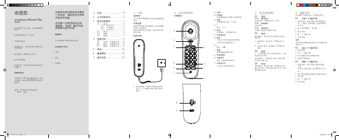
使用您新购买的 Motorola CT50有 线电话
• 可存储10 个记忆号码,实现双键快捷 拨号。 • 重拨最后呼出的一个号码 。 • 音频拨号模式。 • 通话静音后,来电者将听不到您与他 人的对话。 • 静音期间,LED指示灯点亮。
此使用手册可提供您所需的 一切信息,帮助您充分利用 本电话的功能。 在您第一次使用电话之前, 请依照 “安装”章节中的 简易指示进行安装。
3.1 通话................................. 7
3.1.1 拨打电话 ......................7 3.1.2 结束通话 ......................7 3.1.3 接听电话.......................7
D E F
4.2 拨出一个速拨号码
1. 提起手柄。 2. 按一下 速拨 键。 3. 按下速拨号码对应的数字键。 4. 速拨号码被拨出。
3.3 重拨
上一个拨出的号码已存储在电话中;该号 码最长可达32位。 如要重拨上一个拨出的号码,提起手柄, 然后按 重拨 键。
• 铃声音量设置。 • 电话线 • 挂墙使用,可有效利用空间并保持桌 面整洁。 需要帮助吗? 如果您在 CT50 的设置或使用上有任 何问题,请拨打4008-838-698 联系客 服部门。
安装位置
请将CT50放置于距离墙壁上的电话线插 座3米以内的地方。 如果您需要将电话挂墙,请参阅15页的 壁挂安装。 连接电话线
3.2 静音................................. 7 3.3 重拨................................. 7 3.4 转接................................. 7
MOTOROLA MICOM中文使用手册
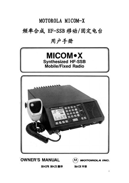
4. 接收声音信号时,可调节 CLARIFIER 使声音自然。本调节对发射频率无效。 5. 电台会保持上次使用的信道,下次开机自动进入。 6. 键盘按动到位时有啪哒感。不要用尖锐物按键以免损坏。 7. 信道选择。两种不同的选择方式:上下箭头和数字键。
钮或按麦克风上的 PTT 键。要扫描少于 10 个信道,在 101 到 110 信道之间不感兴趣的信道 中通过编入 0 来去除其中的频率信息。按 RESET 返回按 SCAN 钮之前使用的信道。
8. 发射 a. 在发射之前先收听。关闭静噪。SQ 钮右上角的灯熄灭。如果是半双工信 道,按 TX/RX 钮监听发射频率的情况。方框将围绕着‘XMIT’直到再 按 RX/TX 钮,或 PTT 钮按下并释放,或 60 秒重设定时器重新设置控制。 如果这信道或频率没人用,扬声器中将听到噪声。如果有人使用,应当改 变信道或等待。 b. 正确握持麦克风 稳定的握住麦克风,网格面对嘴唇约 5cm 距离。 c. 讲话清楚并缓慢 充分按下麦克风侧面的 PTT,功率表图示下面的下划线 出现。如果这信道是单工(收发同频),显示的频率不会改变。如果信道 是半双工(收发不同频),平时显示的是接收频率,PTT 按下去时显示的 是发射频率。用普通声音清楚地缓慢地讲话。说话时观察 RF 功率图示。 产生的 RF 输出大约显示从左至右每一个柱形为 15W 增量。如果天线系 统调谐不合适,产生的反射功率通过从左至右熄灭柱形显示来指示。见下 面图示。
1. 模式 选择下列发射类型之一:SSB,AME。或 PILOT。
2. USB/LSB (可选)选择上边带或下边带用于发射和接收。
3. TX/RX 选择单工(SMPX)或半双工(RCV & XMIT)操作模式。在半双工模式 时也允许监视发射频率。
摩托罗拉 CT220C 有线电话 用户手册说明书

Motorola CT220C 有线电话欢迎您...使用您新购买的摩托罗拉CT220C有线电话!产品特色:• 来电号码及来电时间记录50组(8位)或32组(16位),去电号码14组(8位)或8组(16位)及通话时间记录、翻查、删除、回拨功能• 16位LCD显示• LCD亮度5级可调• 1~99小时免打扰• 16首普通铃声选择• 4档振铃音量及2级免提音量• FLASH时间90/95/100/120/180/300/600/1000ms可选,默认600ms • 3组闹铃功能设置,每组闹铃声音不同• 音乐HOLD功能,并机提机自动解除• 在忘记收线或挂机不好时,自动收线• 8位计算器• 8位出局码• 8位本地码,来电自动过滤• 重拨、暂停、回拨功能• 静音功能• 使用指示灯• 挂机状态,32位预拨号及消号功能• 摘机背光功能• 雷电保护线路需要帮助吗?如果您在CT220C的设置或使用上有任何问题,请拨打4008-838-698 联系客服部门。
1您必须向您的网络提供商申请来电显示服务,方能实现上述功能的使用。
申请可能需要付费。
本说明书可提供您所需的一切信息,帮助您充分利用电话机的功能。
请依照接下来的“使用前的准备”中的简易指示设置好您的电话。
重要事项只可使用产品配备的电话线。
您的配备齐全吗?• 听筒和曲线• 座机• 电话线1.使用前的准备 (6)2.认识您的电话 (8)3.电话功能操作 (11)3.1座机操作说明 (11)3.1.1 拨打电话 (11)3.1.2 挂机预拨号 (11)3.1.3 挂断电话 (11)3.1.4 接听电话 (11)3.2音乐保持 (11)3.3重拨、暂停功能 (11)3.4音量调节 (12)3.5自动收线 (12)3.6关闭送话(静音功能) (12)3.7自动追拨 (12)4.话机设置 (13)4.1设置日期/时间 (13)4.2铃声选择及铃声音量调节 (13)4.3闹铃设置 (13)4.4免打扰时间设定 (14)4.5特殊功能选择设定 (14)4.6本地码与出局码设定 (14)4.7 LCD亮度调节 (14)4.8 IP功能设置 (14)45.回拨 (16)5.1回拨 (16)6.来电记录 (17)6.1来电查询 (17)6.2去电查询 (17)6.3删除功能 (17)7.贵宾存储 (18)8.计算器 (19)8.1 进入计算器模式 (19)9.帮助 (20)10.重要事项 (21)56使用前的准备1. 使用前的准备重要事项不要将CT220C 放置在浴室或其他潮湿的地区。
MOTOMING MOTOROKR E6e GSM 移动电话 说明书
5
清洁方法
请使用干燥的软布清洁手机。请
勿使用酒精或其他清洁剂清洁
引
手机。
防止坠落
言
应避免使手机从高处坠落。
6
引言 .................................................. 1
入门知识 ......................................... 11 关于手册.......................................... 11 原装配件.......................................... 11 SIM 卡 ............................................. 11 电池 ................................................. 13 内存卡 ............................................. 15 开/关机 ............................................ 16 拨打电话.......................................... 17 接听电话.......................................... 18 本机号码.......................................... 18
信息功能......................................... 52 信息中心 ......................................... 52 设置签名 ......................................... 52 发送彩信 ......................................... 53 接收彩信 ......................................... 55 发送短信息...................................... 55 接收文字信息 .................................. 56 查看未发送信息状态 ....................... 57 信息排序 ......................................... 57 查看草稿箱信息 .............................. 57 查看已删除信息 .............................. 57
摩托罗拉说明书
目录1 手持终端介绍1.1 motorola mc31902 手持终端日常操作2.1 充电方法2.2 开关机、热启动、冷启动3 手持终端无线网络配置3.1 无线网络配置4 手持终端联机pc机4.1 概述4.2 同步工具安装4.3 手持终端中文字库安装5 手持终端键盘功能设置 6手持终端机故障分析1 手持终端介绍1.1 motorola mc3190motorola 讯宝symbol mc3190数据采集终端作为symbol mc3090手持终端的升级替代产品,mc3190是构建于成功的mc3090之上,mc3190采集器系列分为3100批处理盘点机和包含无线局域网wifi的mc3190条码采集器两款。
新的摩托罗拉mc3190系列可为公司内部的按键应用提供成本高效的移动性和用户舒适度。
符合人体工程学的耐用型 mc3190 提供先进的计算能力以及数据采集能力、增强的安全性以及企业级的运动传感能力。
motorola 讯宝symbol mc3190数据采集终端性能参数:数据采集选项-1d 激光扫描仪、1d/2d 成像仪、dpm 内存 (flash/ram)-128mb ram/256 mb flash 或 128mb ram/512mb flash 处理器 (cpu)-marvell pxa320 @ 624 mhz 操作系统 (os)-microsoft windows mobile 6.1 classic, microsoft windows ce 6.0 pro 无线数据通讯:wpan(支持蓝牙技术)-ii 级、v2.1 增强数据速率 (edr), 集成天线wlan-三重模式 ieee? 802.11a/b/g;经过 ccxv4 认证;支持 ipv6;经过 fips140-2 认证(仅限mc3190)线性一维条码扫描器:光学分辨率-最小元素宽度 4 mil 扫描速率-104(+/- 12)次扫描/秒(双向)使用环境:环境密封-ip54(2 类)工作温度--4°至 122° f/-20°至 50° c 跌落规格-在工作温度范围内,多次从 4 英尺/1.2 米高处跌至水泥地面;满足并超过mil-std 810g 滚落规格-根据 iec 68-2-32,在室温条件下,500 次从 1.64 英尺/0.5 米高滚落(1,000次)2.1 充电方法摩托罗拉的每个手持终端都配了两粒电池,同时配了四位充电座。
摩托罗拉 有线录音电话 CT111C 使用说明书
4. 微型SD存储卡.......................................13
4.1 安装微型SD存储卡...................................................................... 13
10. 闪断时间.............................................................................19
10.1 更改闪断时间设置...................................................................... 19
9. 铃声.....................................................................................18
9.1 铃声设置....................................................................................... 18 9.2 铃声音量设定.............................................................................. 18
CT111C EN CN.indd 4
23/10/2015 09:15:36
12. 放音密码.............................................................................21
12.1 设置放音密码.............................................................................. 21 12.2 删除放音密码.............................................................................. 21
- 1、下载文档前请自行甄别文档内容的完整性,平台不提供额外的编辑、内容补充、找答案等附加服务。
- 2、"仅部分预览"的文档,不可在线预览部分如存在完整性等问题,可反馈申请退款(可完整预览的文档不适用该条件!)。
- 3、如文档侵犯您的权益,请联系客服反馈,我们会尽快为您处理(人工客服工作时间:9:00-18:30)。
2. 认识您的电话
手柄概览
A B C
D E F
K L
A 听筒
B 挂断键 按此键或挂回手柄即可结束通话。
C 重拨 重拨最后呼出的一个号码。
D* 输入一个* 。
E 转接 转接通话,需交换机支持。
F 听筒麦克风
G 静音 与他人交谈而不被来电者听到。 点亮时表示通话静音中。
H#
G
输入一个#。
I 速拨 存储或提取速拨号码。
3.2 静音................................. 7 3.3 重拨................................. 7 3.4 转接................................. 7
4. 速拨号码................................ 8
• 勿在靠近水源的地方使用电话 (例 如:在浴盆附近、厨房洗涤盆 附近或 都游泳池附近。)
• 勿拆卸本产品。如果需要任何服务或 是维修,请在使用说明书中找出客服 热线,联系客服中心为您服务。
• 避免在雷雨天气下使用。使用过浪涌 电压保护器保护设备。
安装指引 • 阅读并理解所有的安装指引并存放好
说明书以供日后参考。
您的配备齐全吗?
• 手柄
• 底座
• 电话线
1. 安装......................................... 4
2. 认识您的电话........................ 5
3. 电话功能操作........................ 7
3.1 通话................................. 7 3.1.1 拨打电话 ......................7 3.1.2 结束通话 ......................7 3.1.3 接听电话.......................7
4.1 存储一个速拨号码........ 8 4.2 拨出一个速拨号码........ 8 4.3 删除一个速拨号码........ 8
5. 帮助....................................... 10
6. 重要事项.............................. 11
需要帮助吗?
如果您在 CT50 的设置或使用上有任 何问题,请拨打4008-838-698 联系客 服部门。
或者,您可参阅本手册最后的 “ 帮助” 说明。
此使用手册可提供您所需的 一切信息,帮助您充分利用 本电话的功能。
在您第一次使用电话之前, 请依照 “安装”章节中的 简易指示进行安装。
重要事项
只可使用随产品配备的电话线。
4.2 拨出一个速拨号码 1. 提起手柄。 2. 按一下 速拨 键。 3. 按下速拨号码对应的数字键。 4. 速拨号码被拨出。
4.3 删除一个速拨号码 1. 提起手柄,长按 速拨 键至听到提
示音。 此时位于静音键上方的LED指示灯点 亮。
2. 按下您想要删除的速拨号码所对应的 数字键。
3. 按一下 速拨 键。 4. 挂回手柄。
7. 壁挂安装.............................. 15
1. 安装
重要事项 请不要将CT50放置于浴室或其他潮湿的 地方。
安装位置 请将CT50放置于距离墙壁上的电话线插 座3米以内的地方。 如果您需要将电话挂墙,请参阅15页的 壁挂安装。
连接电话线
1. 将电话线的一端插入手柄的电话线 接口,另一端插入墙壁上的电话线 插座。
授权维修中心
要获得服务,你必须包括:(a) 产品或配 件;(b) 原购买证明(收据),其中包括日 期,地点和产品的销售者;(c) 如果保修 卡是包含在包装盒里的,完整的保修卡
上会显示本产品序列号;(d) 对问题的书 面说明; 以及最重要的;(e) 您的地址和 电话号码。
技术信息
连接至接线总机 本产品适合于中国地区连接公共电话网 络使用。
消费性电子产品及配件保修 感谢您购买摩托罗拉品牌产品。本产品 由摩托罗拉公司授权新确制造。“新确 科技有限公司” ;简称“新确”,位于 中国香港湾仔海港路26号中国资源大厦 3001-3005。
保修单涵盖了哪些项目? 根据下面的免责条款,新确承诺:本摩托 罗拉品牌产品或其它为配合本产品使用而 生产的配件是采用无瑕疵材料及生产工艺 制造而成,在下面说明的使用时间内可供 给消费者正常使用。本保修单受益人仅为 购买者本身,转让无效。
CT50 CS UG_V4.indd 9-16
5. 帮助
没有拨号音 • 仅适用随产品配备的电话线。 • 检查电话线是否有正确连接。
存储速拨号码 • 速拨号码存储成功时,话机没有提示
音,请直接将手柄挂回。 • 请注意将速拨号码记录在速拨号码列
表卡上的对应数字后面。
没有声音
• 静音已开启,按 静音 键关闭静音 功能。
1. 通话期间,按 静音,LED指示灯点 亮。
2. 再次按 静音 关闭静音,LED指示灯 熄灭。
3.3 重拨 上一个拨出的号码已存储在电话中;该号 码最长可达32位。 如要重拨上一个拨出的号码,提起手柄, 然后按 重拨 键。
3.4 转接 通话期间,按 转接 键,听到拨号音后, 拨分机号码,将来电转给其它分机,需交 换机配合使用。
J 电话线接口
K 设置铃声 调高、调低或关闭铃声。
H
L 来电指示灯
点亮表示话机收到来电。
I
J
3. 电话功能操作
3.1 通话 3.1.1 拨打电话 提起手柄,听到拨号音时,拨号。
3.1.2 结束通话 挂回手柄。
3.1.3 接听电话 从底座上提起手柄接听来电。
3.2 静音 通话静音,使来电者无法听到您与他人 的对话。
使用非摩托罗拉品牌的产品及配件。因使 用非摩托罗拉品牌的产品或配件导致的产 品不良或是使用其它外部设备导致的产品 不良不在保修范围之内。
未经授权的服务或检修。因摩托罗拉、新 确或其授权以外的人对产品提供任何形式 的测试、检测、安装、维修、改动或是检 修而导致产品不良不在保修范围之内。
产品更改。产品或配件本身的 (a) 序列号 或日期贴纸被撕毁、更改或除去;(b) 密 封件的损坏或篡改证据;(c) 混错箱装序 号或 (d) 不一致的或非摩托罗拉品牌的 外壳,或部件,均不在保修范围之内。
抗静电抹布来清理子机和主机。 • 切勿使用家俱光亮剂,否则可能造成
产品损坏。此外请勿使用干布擦拭, 因为可能产生静电现象。
环境相关信息 • 请勿将产品曝露在阳光直射处。 • 请勿将产品放置在地毯或其它纤维可
能脱落的表面,或将它放置在表面通 风不良的位置。 • 请勿将本产品任何一部份浸入水中, 也勿在潮湿的环境中使用本产品,例 如浴室内。 • 请勿将本产品暴露在有火源、爆炸或 其它危险情况的场所。
CT50 CS UG_V4.indd 1-8
19/07/2016 10:46
新确科技有限公司已获得官方 许可制造、经销及出售该产 品。MOTOROLA及M字样的标志是 Motorola Trademark Holdings, LLC所 有的商标或注册商标,并在其授权下 使用。所有其它商标均为其各自所 有的财产。© 2016 Motorola Mobility LLC。保留所有权。 制造商:深圳国威电子有限公司 地址:中国深圳市罗湖区莲塘罗沙路 3038号国威电子大厦 工厂:梅州国威电子有限公司 地址:中国广东省梅州市东升工业园 区AD1区 Version 6 (CS) Shenzhen Guo Wei Electronics Co., Ltd 深圳国威电子有限公司, 中国深圳市罗湖区莲塘罗沙路3038号 国威电子大厦
4. 速拨号码
可存储10个速拨号码,号码最长32位。
4.1 存储一个速拨号码 1. 提起手柄,长按 速拨 键至听到提示
音。 此时位于静音键上方的LED指示 灯点亮。
2. 按下从0到9的任一数字键。 3. 输入号码。 4. 按一下 速拨 键。 5. 挂回手柄。
注意 请注意将存储的速拨号码记录在速拨号码 列表卡上。
通信服务。因消费者订购的任何通信服 务或是信号的服务不良而导致产品或配 件有瑕疵、受损或是不良,均不在保修 范围之内。
如何获取保修服务或是其它信息?
需要获取服务信息请拨打:4008-838-698
您将会收到指示如何将产品或配件以自费 的方式寄给新确。购买方需与最近的授权 服务中心/经销商保持联系以降低产品在 寄给授权服务中心时过程雷击 损坏。因此我们建议您在雷电风暴期 间最好将电话线拔除。
废旧产品的处置指示 住宅用户的废旧产品处置指示 对于不再使用的产品,请依照您当地管制 机关规定的回收程序处置产品。如需进一 步的详情,请联系您当地的有关当局或购 买此产品的零售商。
商业用户的废旧产品处置指示 商业用户应联系其供货商并查阅购买协议 的条款及条件,同时确保未将本产品与其 它商业废弃物一起弃置。
• 遵守所有产品的警告及指示标志。
• 勿在浴盆、水槽或是淋浴喷头附近安 装产品。
• 勿将本产品放置于不稳固的手推车、 台面或是桌子上。这会使产品跌落导 致严重损坏。
• 只能设置说明书上所提到的相关控制 参数,其它参数不正确的设置会损坏 机器,而且需要做大量的工作以恢复 产品的正常运作。
清洁方法 • 请用稍微润湿的布 (勿使用湿布) 或
闪断功能 如果您的电话与接线总机连接,可能需要 使用闪断功能。请联系您的PABX 供应商 了解进一步的信息。
消费性电 子产品及 配件的维 修及更换
初次维修后剩余的时间或 是 90 天,从返还给客户 之日起计算,以较长的时 间为准。
不包括项目
正常磨损。定期维修,修复及更换因正常 使用导致磨损的部件不在保修范围之内。