DASEN-3i_连接手册
ICP DAS WinCon8000 Series 硬件用户手册说明书

• WinCon 8000 Series
The WinCon 8000 is the flagship compact embedded controller manufactured by ICP DAS. Its leading technology gives you all of the best features of both traditional PLCs and Windows capable PCs. The WinCon 8000 system is powered by Windows and brings Windows programming style and skill into the world of PC-based PLCs. Application developers can directly develop their own programs in Microsoft’s Visual Studio .NET and Embedded Visual tools with the WinCon SDK, and then download them into WinCon 8000 for use. Or, they can port their favorite SCADA software onto WinCon 8000 for even easier application development. For SCADA applications, we also provide a product model embedded with InduSoft Web Studio run-time version to meet this need.
ICP DAS DL-100TM485 用户手册说明书
and the parity, data bits and stop bits are fixed as no
parity, 8 data bits and 1 stop bit. The following Modbus
functions are supported.
1/4 1/3 3.0 V 64 Hz
Power reverse polarity protection +10 ~ +30 VDC ≤ 0.15 W @ 24 VDC
86 mm x 128 mm x 52 mm
-20 ~ +60℃ -30 ~+80℃ 5 ~ 95% RH, Non-condensing
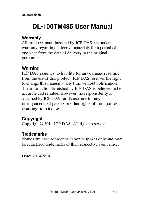
ΔT (±℃)
3 2.5
2 1.5
1 0.5
0 -40 -30 -20 -10 0 10 20 30 40 50 60 70 80 90 100 Temperature (℃)
Figure 2: Maximum T-tolerance per sensor.
DL-100TM485 User Manual, V1.01
1 Hardware Information....................................................................................4 1.1 Specifications...........................................................................................4 1.2 Function Block ........................................................................................6 1.3 Pin Assignments ......................................................................................6 1.4 Wire Connections ....................................................................................7 2 Modbus RTU Protocol ................................................................................8 2.1 Modbus Mapping Table .............................................................................9 3 Utility Software............................................................................................13 3.1 Before you use the Utility Software.........................................................13 3.2 DL-100TM485 Utility .............................................................................14 3.3 Configuration ...........................................................................................15 4 Appendix......................................................................................................16 4.1 LCD Information: ....................................................................................16
DAAS3L操作手册
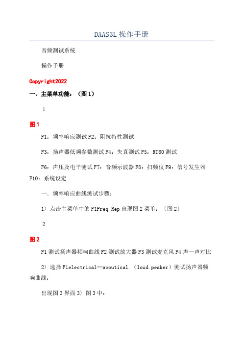
DAAS3L操作手册音频测试系统操作手册Copyright2022一、主菜单功能:(图1)1图1F1:频率响应测试F2:阻抗特性测试F3:扬声器低频参数测试F4:失真测试F5:RT60测试F6:声压及电平测试F7:音频示波器F8:扫频仪F9:信号发生器F10:系统设定一.频率响应曲线测试步骤:1〉点击主菜单中的F1Freq.Rep出现图2菜单:〔图2〕2图2F1测试扬声器频响曲线F2测试放大器F3测试麦克风F4声一声对比2〉选择F1electrical─acoutical.(loud.peaker)测试扬声器频响曲线:出现图3界面3〉图3中:F10.2V,F22V,F320V均为系统测试量程。
大信号测试,如测频响时选择F320V,小信号测试,如测试阻抗时选择F10.2V。
F4UeLat:使用先前的测试结果。
如先前做过这一步骤并且现在想跳过这一步,可选择F4UelatF5Load为调出一个预存的测试数据。
F9Out.Att.为调整信号输出的大小。
F10Sample.rate.设定取样频率及测量范围:(见图4)F164KHZ:测试范围27HZ—26667HZF248KHZ:测试范围20HZ—20000HZF36KHZ:测试范围3HZ—2500HZ注:在本系统中,相同标示的按键有着相同的功能,并不一定要一一讲述3图3图43>选择按F320V测量放大器输出电压,(如图3)4〉选按F320V后出现图5界面(图5)4图5在图5中:按F1OK继续执行测试图65图7图8按F2Repeat重做该测试步骤按F4Print打印该幅图形按F5Save存储图形5〉选按F1OK则继续下一步测试6〉选择F28Pa(图6)7〉选择F1OK(图7)即可得到扬声器频响曲线(图8)68〉在显示频响曲线界面中(图8)F1Repeat:重做上一步骤F2Freetield:自由音场校正F3Phae:相位特性F4Print:打印图形F5Load/ave:调出存储的图形F6Waterfall:显示瀑布图F7Steprep:阶梯响应计算F8Diplrange:调整图形座标及分辨率F9QuickRepeat:快速重测键F10Function:其它功能设定图99〉图8中其它功能说明1)点击F2Freefield自由音场校正,得到如图9界面F1OK:返回上一面界面F2、F3、F7、F8:调整座标F4、F5、F9、F10:水平垂直方向缩放F6:显示ETC结果2)点击F3Phae得到红色相位特性图(如图10)在相位菜单内:7图10F1OK:回到上一界面F3minimalphae:最小相位换算F4Print:图形打印F5E某port:输出CAD数据F6F7:缩放座标F9:Delay:延迟特性83)点击F6waterfall得到瀑布图(图11)F1OK返回上一界面4)点击F8DipLrange调整纵横向座标及分辨率(图12)图12F1Setupfrequeneya某i调整水平显示范围F2Setupmagnitudea某i 调整整纵向分辨率5)点击F10Function,进入其它功能设定(图13)F1E某portcurve:储存当前测试曲线F2Correctditanceloudpeaker—mic:手动修正扬声器与麦克风之距离F3Makload/ave/import/new:品管功能键见操作手册之品管功能说明F4Smoofh:平滑键提示:1)在测完频响曲线后,按住鼠标右键并拖动,可显示曲线上任何一点的测试值2)曲线可利用光标键上下移动。
WSEN-ISDS应用指南:使用单I2C总线连接多个传感器说明书

ANM005-U SING MULTIPLE SENSORS ONSINGLE I2C B USV ERSION1.1F EBRUARY7,2023Revision historyContents1Introduction3 2How to implement multiple sensors with same I2C Address?42.1Multiplexers (4)2.2De-selecting not required sensors through GPIO pins of microcontroller..5 3Important notes73.1General customer responsibility (7)3.2Customer responsibility related to specific,in particular safety-relevant ap-plications (7)3.3Best care and attention (7)3.4Customer support for product specifications (7)3.5Product improvements (8)3.6Product life cycle (8)3.7Property rights (8)3.8General terms and conditions (8)4Legal notice94.1Exclusion of liability (9)4.2Suitability in customer applications (9)4.3Usage restriction (9)5License terms for Würth Elektronik eiSos GmbH&Co.KG sensor product software and source code115.1Limited license (11)5.2Usage and obligations (11)5.3Ownership (12)5.4Disclaimer of warranty (12)5.5Limitation of liability (12)5.6Applicable law and jurisdiction (12)5.7Severability clause (13)5.8Miscellaneous (13)Two of each WSEN-P ADS,WSEN-TIDS,WSEN-ISDS and WSEN-ITDS could be connected to the same I 2C bus since,two I 2C slave addresses (based on the SAO pin connection)are available for these sensors.Only one of each WSEN-HIDS and WSEN-PDUS could be connected to a single I 2C bus since only one I 2C slave address is available.Figure 1:T wo WSEN-PADS with separate slave address on an I 2C busHowever,some applications require the use of same sensors multiple times on a single I 2C bus.For example,to have more than two pressure sensors on a single I 2C bus.In these cases,the maximum number of devices that could be connected to the I 2C bus depends on the available slave addresses of that particular device.I 2C with the same I 2Ca multiplexer.The selects whichever be resolved and WSEN-HIDSWSEN-HIDS WSEN-HIDS WSEN-HIDSSensor SCL Sensor SDAFigure 2:Multiple sensors with one I 2C address connected through multiplexer For example TCA9548A from T exas Instruments is an 8-Channel I 2C multiplexer and can support up to 8-devices.The Multiplexer has 8bidirectional translating switches that can be controlled through the I 2C bus from the master.Each channel consists of a pair of data and clock line and any individual channel or combination of channels can be selected through the programmable registers.Figure3:Application diagram of Multiplexer TCA9548A2.2De-selecting not required sensors through GPIO pins ofmicrocontrollerUsing microcontroller GPIO pins,each sensor can be taken into operation(GPIO Pin logic HIGH)one by one,and keeping rest of the sensors de-selected(GPIO logic LOW).Hence, at a time,only one sensor is in working state.This set-up requires use of multiple GPIO pins on the microcontroller side.For example,WSEN-TIDS SAO pin can be connected to the GPIO pins of microcontroller. By switching the SAO pins of each sensor high one by one,each TIDS sensor can be addressed through one I2C address(SAO=High=0x38).Rest of the TIDS sensors have their SAO pins at logic LOW with I2C address0x3F and hence they are de-selected. Number of sensors that can be attached to the microcontroller in this way also depends upon the number of available GPIO pins.This is possible only for the sensors with two I2C address.(WSEN-ITDS,WSEN-ISDS,WSEN-PADS and WSEN-TIDS.Figure 4:Sensor-1in operation with I 2C address 0x38because GPIO-1is highFigure 5:Sensor-2in operation with I 2C address 0x38because GPIO-2is high3Important notesThe following conditions apply to all goods within the sensors product range of Würth Elek-tronik eiSos GmbH&Co.KG:3.1General customer responsibilitySome goods within the product range of Würth Elektronik eiSos GmbH&Co.KG contain statements regarding general suitability for certain application areas.These statements about suitability are based on our knowledge and experience of typical requirements con-cerning the areas,serve as general guidance and cannot be estimated as binding statements about the suitability for a customer application.The responsibility for the applicability and use in a particular customer design is always solely within the authority of the customer.Due to this fact,it is up to the customer to evaluate,where appropriate to investigate and to decide whether the device with the specific product characteristics described in the product speci-fication is valid and suitable for the respective customer application or not.Accordingly,the customer is cautioned to verify that the documentation is current before placing orders. 3.2Customer responsibility related to specific,in particularsafety-relevant applicationsIt has to be clearly pointed out that the possibility of a malfunction of electronic components or failure before the end of the usual lifetime cannot be completely eliminated in the current state of the art,even if the products are operated within the range of the specifications. The same statement is valid for all software and software parts contained in or used with or for products in the sensor product range of Würth Elektronik eiSos GmbH&Co.KG. In certain customer applications requiring a high level of safety and especially in customer applications in which the malfunction or failure of an electronic component could endanger human life or health,it must be ensured by most advanced technological aid of suitable design of the customer application that no injury or damage is caused to third parties in the event of malfunction or failure of an electronic component.3.3Best care and attentionAny product-specific data sheets,manuals,application notes,PCN’s,warnings and cau-tions must be strictly observed in the most recent versions and matching to the products revisions.This documents can be downloaded from the product specific sections on the wireless connectivity and sensors homepage.3.4Customer support for product specificationsSome products within the product range may contain substances,which are subject to re-strictions in certain jurisdictions in order to serve specific technical requirements.Necessary information is available on request.In this case,thefield sales engineer or the internal sales person in charge should be contacted who will be happy to support in this matter.3.5Product improvementsDue to constant product improvement,product specifications may change from time to time. As a standard reporting procedure of the Product Change Notification(PCN)according to the JEDEC-Standard,we inform about major changes.In case of further queries regarding the PCN,thefield sales engineer,the internal sales person or the technical support team in charge should be contacted.The basic responsibility of the customer as per section3.1 and3.2remains unaffected.The sensor driver software¨Sensor SDK¨and it’s source codes are not subject to the Prod-uct Change Notification information process.3.6Product life cycleDue to technical progress and economical evaluation we also reserve the right to discon-tinue production and delivery of products.As a standard reporting procedure of the Product Termination Notification(PTN)according to the JEDEC-Standard we will inform at an early stage about inevitable product discontinuance.According to this,we cannot ensure that all products within our product range will always be available.Therefore,it needs to be verified with thefield sales engineer or the internal sales person in charge about the current product availability expectancy before or when the product for application design-in disposal is con-sidered.The approach named above does not apply in the case of individual agreements deviating from the foregoing for customer-specific products.3.7Property rightsAll the rights for contractual products produced by Würth Elektronik eiSos GmbH&Co.KG on the basis of ideas,development contracts as well as models or templates that are subject to copyright,patent or commercial protection supplied to the customer will remain with Würth Elektronik eiSos GmbH&Co.KG.Würth Elektronik eiSos GmbH&Co.KG does not warrant or represent that any license,either expressed or implied,is granted under any patent right, copyright,mask work right,or other intellectual property right relating to any combination, application,or process in which Würth Elektronik eiSos GmbH&Co.KG components or services are used.3.8General terms and conditionsUnless otherwise agreed in individual contracts,all orders are subject to the current ver-sion of the"General Terms and Conditions of Würth Elektronik eiSos Group",last version available at .4Legal notice4.1Exclusion of liabilityWürth Elektronik eiSos GmbH&Co.KG considers the information in this document to be correct at the time of publication.However,Würth Elektronik eiSos GmbH&Co.KG re-serves the right to modify the information such as technical specifications or functions of its products or discontinue the production of these products or the support of one of these products without any written announcement or notification to customers.The customer must make sure that the information used corresponds to the latest published information.Würth Elektronik eiSos GmbH&Co.KG does not assume any liability for the use of its products. Würth Elektronik eiSos GmbH&Co.KG does not grant licenses for its patent rights or for any other of its intellectual property rights or third-party rights.Notwithstanding anything above,Würth Elektronik eiSos GmbH&Co.KG makes no repre-sentations and/or warranties of any kind for the provided information related to their accuracy, correctness,completeness,usage of the products and/or usability for customer applications. Information published by Würth Elektronik eiSos GmbH&Co.KG regarding third-party prod-ucts or services does not constitute a license to use such products or services or a warranty or endorsement thereof.4.2Suitability in customer applicationsThe customer bears the responsibility for compliance of systems or units,in which Würth Elektronik eiSos GmbH&Co.KG products are integrated,with applicable legal regulations. Customer acknowledges and agrees that it is solely responsible for compliance with all le-gal,regulatory and safety-related requirements concerning its products,and any use of Würth Elektronik eiSos GmbH&Co.KG components in its applications,notwithstanding any applications-related in-formation or support that may be provided by Würth Elektronik eiSos GmbH&Co.KG.Customer represents and agrees that it has all the necessary expertise to create and implement safeguards which anticipate dangerous consequences of failures, monitor failures and their consequences lessen the likelihood of failures that might cause harm and take appropriate remedial actions.The customer will fully indemnify Würth Elek-tronik eiSos GmbH&Co.KG and its representatives against any damages arising out of the use of any Würth Elektronik eiSos GmbH&Co.KG components in safety-critical applica-tions.4.3Usage restrictionWürth Elektronik eiSos GmbH&Co.KG products have been designed and developed for usage in general electronic equipment only.This product is not authorized for use in equip-ment where a higher safety standard and reliability standard is especially required or where a failure of the product is reasonably expected to cause severe personal injury or death, unless the parties have executed an agreement specifically governing such use.Moreover, Würth Elektronik eiSos GmbH&Co.KG products are neither designed nor intended for use in areas such as military,aerospace,aviation,nuclear control,submarine,transportation (automotive control,train control,ship control),transportation signal,disaster prevention, medical,public information network etc.Würth Elektronik eiSos GmbH&Co.KG must be informed about the intent of such usage before the design-in stage.In addition,sufficient reliability evaluation checks for safety must be performed on every electronic component,which is used in electrical circuits that require high safety and reliability function or perfor-mance.By using Würth Elektronik eiSos GmbH&Co.KG products,the customer agrees tothese terms and conditions.5License terms for Würth Elektronik eiSosGmbH&Co.KG sensor product software and source codeThis License terms will take effect upon the purchase and usage of the Würth Elektronik eiSos GmbH&Co.KG sensor products.Y ou hereby agree that this license terms are appli-cable to the product and the incorporated software,firmware and source codes(collectively, "Software")made available by Würth Elektronik eiSos in any form,including but not limited to binary,executable or source code form.The software included in any Würth Elektronik eiSos sensor product is purchased to you on the condition that you accept the terms and conditions of this license terms.Y ou agree to comply with all provisions under this license terms.5.1Limited licenseWürth Elektronik eiSos hereby grants you a limited,non-exclusive,non-transferable and royalty-free license to use the software and under the conditions that will be set forth in this license terms.Y ou are free to use the provided software only in connection with one of the products from Würth Elektronik eiSos to the extent described in this license terms.Y ou are entitled to change or alter the source code for the sole purpose of creating an ap-plication embedding the Würth Elektronik eiSos sensor product.The transfer of the source code to third parties is allowed to the sole extent that the source code is used by such third parties in connection with our product or another hardware provided by Würth Elektronik eiSos under strict adherence of this license terms.Würth Elektronik eiSos will not assume any liability for the usage of the incorporated software and the source code.Y ou are not entitled to transfer the source code in any form to third parties without prior writ-ten consent of Würth Elektronik eiSos.Y ou are not allowed to reproduce,translate,reverse engineer,decompile,disassemble or create derivative works of the incorporated software and the source code in whole or in part. No more extensive rights to use and exploit the products are granted to you.5.2Usage and obligationsThe responsibility for the applicability and use of the Würth Elektronik eiSos sensor product with the incorporated software in a particular customer design is always solely within the authority of the customer.Due to this fact,it is up to you to evaluate and investigate,where appropriate,and to decide whether the device with the specific product characteristics de-scribed in the product specification is valid and suitable for your respective application or not.Y ou are responsible for using the Würth Elektronik eiSos sensor product with the incorpo-rated software in compliance with all applicable product liability and product safety laws.Y ou acknowledge to minimize the risk of loss and harm to individuals and bear the risk for failure leading to personal injury or death due to your usage of the product.Würth Elektronik eiSos’products are not authorized for use in safety-critical applications, or where a failure of the product is reasonably expected to cause severe personal injury or death.Moreover,Würth Elektronik eiSos’products are neither designed nor intended for use in areas such as military,aerospace,aviation,nuclear control,submarine,trans-portation(automotive control,train control,ship control),transportation signal,disaster pre-vention,medical,public information network etc.Y ou shall inform Würth Elektronik eiSos about the intent of such usage before design-in stage.In certain customer applications re-quiring a very high level of safety and in which the malfunction or failure of an electronic component could endanger human life or health,you must ensure to have all necessary ex-pertise in the safety and regulatory ramifications of your applications.Y ou acknowledge and agree that you are solely responsible for all legal,regulatory and safety-related requirements concerning your products and any use of Würth Elektronik eiSos’products in such safety-critical applications,notwithstanding any applications-related information or support that may be provided by Würth Elektronik eiSos.YOU SHALL INDEMNIFY WÜRTH ELEKTRONIK EISOS AGAINST ANY DAMAGES ARISING OUT OF THE USE OF WÜRTH ELEKTRONIK EISOS’PRODUCTS IN SUCH SAFETY-CRITICAL APPLICA TIONS.5.3OwnershipThe incorporated Software created by Würth Elektronik eiSos is and will remain the exclusive property of Würth Elektronik eiSos.5.4Disclaimer of warrantyTHE SOFTWARE AND IT’S SOURCE CODE IS PROVIDED"AS IS".YOU ACKNOWL-EDGE THA T WÜRTH ELEKTRONIK EISOS MAKES NO REPRESENTATIONS AND WAR-RANTIES OF ANY KIND RELATED TO,BUT NOT LIMITED TO THE NON-INFRINGEMENT OF THIRD P ARTIES’INTELLECTUAL PROPERTY RIGHTS OR THE MERCHANTABIL-ITY OR FITNESS FOR YOUR INTENDED PURPOSE OR USAGE.WÜRTH ELEKTRONIK EISOS DOES NOT WARRANT OR REPRESENT THAT ANY LICENSE,EITHER EXPRESS OR IMPLIED,IS GRANTED UNDER ANY PATENT RIGHT,COPYRIGHT,MASK WORK RIGHT,OR OTHER INTELLECTUAL PROPERTY RIGHT RELATING TO ANY COMBINA-TION,MACHINE,OR PROCESS IN WHICH THE WÜRTH ELEKTRONIK EISOS’PROD-UCT WITH THE INCORPORATED SOFTWARE IS RMA TION PUBLISHED BY WÜRTH ELEKTRONIK EISOS REGARDING THIRD-PARTY PRODUCTS OR SERVICES DOES NOT CONSTITUTE A LICENSE FROM WÜRTH ELEKTRONIK EISOS TO USE SUCH PRODUCTS OR SERVICES OR A WARRANTY OR ENDORSEMENT THEREOF.5.5Limitation of liabilityAny liability not expressly provided by Würth Elektronik eiSos shall be disclaimed.Y ou agree to hold us harmless from any third-party claims related to your usage of the Würth Elektronik eiSos’products with the incorporated software and source code.Würth Elektronik eiSos disclaims any liability for any alteration,development created by you or your customers as well as for any combination with other products.5.6Applicable law and jurisdictionApplicable law to this license terms shall be the laws of the Federal Republic of Germany. Any dispute,claim or controversy arising out of or relating to this license terms shall be resolved andfinally settled by the court competent for the location of Würth Elektronik eiSos registered office.5.7Severability clauseIf a provision of this license terms are or becomes invalid,unenforceable or null and void, this shall not affect the remaining provisions of the terms.The parties shall replace any such provisions with new valid provisions that most closely approximate the purpose of the terms.5.8MiscellaneousWürth Elektronik eiSos reserves the right at any time to change this terms at its own discre-tion.It is your responsibility to check at Würth Elektronik eiSos homepage for any updates. Y our continued usage of the products will be deemed as the acceptance of the change. We recommend you to be updated about the status of new software,which is available on our website or in our data sheet,and to implement new software in your device where ap-propriate.By ordering a sensor product,you accept this license terms in all terms.List of Figures1T wo WSEN-PADS with separate slave address on an I2C bus (3)2Multiple sensors with one I2C address connected through multiplexer (4)3Application diagram of Multiplexer TCA9548A (5)4Sensor-1in operation with I2C address0x38because GPIO-1is high (6)5Sensor-2in operation with I2C address0x38because GPIO-2is high (6)References[1]International Organization for Standardization;Standard Atmosphere;1975;ISO2533:1975.[2]Manual of the ICAO Standard Atmosphere(extended to80kilometres)(3rd edi-tion);International Civil Aviation Organization;1993;ISBN978-92-9194-004-2.Doc7488-CD.Monitoring & Control Automated Meter ReadingInternet of Things。
仪器复用用户手册说明书

四 注意事项 .................................................................................................................................... 19
五 故障排查 .................................................................................................................................... 20
硬件配置:对数据服务器硬件配置:CPU 双核 1.8GGHz 以 上、内存 4GB 以上、硬盘 500GB 以上;
软件配置:对测试数据服务器端操作系统可选用 Windows
以上操作系统,适用安装 和 sever 2008 R2
SQL 5.6 Idea-A-
系统服务。
2.1.2 用户管理端(设置端)配置
进入安装界面,点击
键进行安装;
进安入装安完装成过后程,;自动进入仪器复用软件置好Internet Explorer 浏览 器环境;
参数说明书(3i)

本使用说明中把安全注意事项的等级分为三个层次︰危险、报警和注意。
! 危险
不适当的操作会出现导致操作者死亡或重伤的危险。
3. 关于维修的注意事项 通电状态下请勿进行电池更换。 请勿对电池进行短路、充电、高温、焚烧及分解操作。 更换下来的电池请按照当地法规规定的方法进行处理。
4. 关于伺服参数、主轴参数的注意事项 参数的极端调整和更改会导致工作不稳定,请勿进行此操作。 关于位元的说明,包括空位在内,未使用的位元全部设定为“0”。
! 注意 ! 如果本说明书中关于“限制事项”和“允许条件”的说明与机床制造商的规格说明书中的说 明有冲突,则以后者为准。 ! 本说明书中未加说明的操作被认为是不可能进行的。
! 本说明书是设想您的机床具备 DASEN-3i 装置全部功能而拟订的。在进行操作之前,务必
请先参阅机床制造商提供的规格说明书,确认您的机床所具有的功能。 ! 根据 NC 系统的版本不同,画面/功能会有不同,会有某些功能不能使用。
关于阅读本说明书的注意事项
(1) 本说明书从 NC 角度阐述一般参数。 有关各工作机械的说明,请参阅机床制造商出版的说明书。如果有关“限制事项”和“允许 条件”,本说明书与机床制造商的说明书有矛盾时,则以机床制造商的说明书为准。
(2) 本说明书力求包括尽可能多的内容,包括特殊操作。本说明书中未加说明的操作被认为是不 可能进行的。
DASEN-3i
报警/参数说明书
请仔细阅读本手册,并作为后续参考
大森数控
前言
本说明书是使用 DASEN-3i 控制器时所需的报警/参数指南。 本说明书是设想您的机床具备 DASEN-3i 控制器全部功能而拟订的,但 NC 控制器中,不
大森数控 DASEN-9i 说明书
DASEN-9i操作手册编程手册请仔细阅读本手册,并作为后续参考目录Ⅰ编程操作第一部分 概述 (1)1.规格 (2)1.1基本功能 (2)1.2辅助功能 (6)1.3 主轴功能 (6)1.4 刀具功能 (6)1.5 编辑 (6)2.地址码一览表 (7)3.G码一览表 (7)4.辅助功能(M2位数) (9)4.1 自动方式 (9)4.2 手动方式 (9)5.CRT/MDI面板的说明 (10)6.机床操作面板的说明 (12)6.1方式选择 (12)第二部分手动加工 (17)1.概述 (17)2.机床的启动 (17)2.1 通电 (17)2.2 机械原点的设定 (18)3.电源关闭 (19)4.手动方式操作 (19)4.1 设定手动方式 (19)4.2 手动方式显示的坐标系切换 (19)4.3 手动方式坐标系的建立 (21)4.4 手动点动进给(JOG进给) (24)4.5 手轮进给 (25)4.6 主轴控制 (26)4.7 冷却控制 (26)第三部分编制程序 (27)1.概述 (27)2.程序结构 (27)2.1 程序段 (27)2.2 字(地址码) (28)2.3 输入方式 (28)2.4 小数点输入方式 (28)2.5 程序名称 (29)2.6 顺序号 (29)2.7 选择性程序跳步 (29)3.控制轴和坐标系 (29)3.1 控制轴 (29)3.2 坐标系 (30)3.3 进给功能 (31)4.准备功能(G指令) (34)4.1 位置定位(快速进给:G00) (34)4.2 直线插补(G01) (36)4.3 圆弧插补(G02,G03) (38)4.4 平面选择(G18) (42)4.5暂停(G04) (43)4.6精定位 (G09) (44)4.7英制指令/公制指令转换(G20,G21) (47)4.8参考点(原点)复归 (G28, G29) (47)4.9返回第2~4参考点(G30) (48)4.10螺纹切削(G32) (55)4.11 刀尖R补偿(G40,G41,G42) (57)4.12加工坐标系设定(G50) (65)4.13 本地坐标系(G52) (67)4.14机械坐标系选择(G53) (68)4.15选择加工坐标系(G54~G59) (69)4.16外径切削固定循环(G90) (71)4.17螺纹切削固定循环(G92) (72)4.18端面固定循环(G94) (74)4.19恒线速控制(G96,G97) (76)4.20每分进给 每转进给(G98,G99) (77)5.辅助功能(M指令) (79)5.1 程序停止(M00) (79)5.2 选择停止(M01) (79)5.3 程序结束(M02,M30) (79)5.4 子程序控制(M98,M99) (80)6.主轴功能(S码)、刀具功能(T码) (85)6.1 主轴功能 (85)6.2 刀具功能 (85)7.子程序 (86)7.1 子程序的编制 (86)7.2子程序执行 (86)8.综合编程实例 (87)第四部分MDI运行 (89)1.概述 (89)2.MDI操作 (89)2.1 MDI方式 (89)2.2 显示内容的选择 (89)2.3 模态数据显示 (92)2.4 坐标系设定 (93)2.5 点位控制 (94)2.6 直线插补 (95)2.7 圆弧插补 (96)2.8 固定循环 (97)2.9 子程序 (99)2.10 刀尖R补偿 (100)2.11 其他指令 (100)第五部分自动加工 (101)1.概述 (101)2.编辑 (101)2.1 概述 (101)2.2 编辑页面的说明 (102)3.程序的输入方法 (103)3.1 NC指令输入程序 (103)3.2 编辑键的使用方法 (104)3.3 编辑的注意事项 (105)3.4 编辑程序 (106)3.5程序的清除 (111)3.6 程序的更名 (112)3.7 程序的复制 (113)4.刀补的设定 (114)4.1 概述 (115)4.2 刀补设定 (116)4.3 刀补的清除 (121)4.4 刀补值输入 (121)4.5 刀补值输出 (121)5.自动方式操作方法 (122)5.1 急停 (122)5.2 复位 (122)5.3 循环启动 (122)5.4 进给保持 (123)5.5 单程序段 (123)5.6 选择停止 (123)5.7 空运行 (123)5.8 辅助功能锁住 (124)5.9 机床锁住 (124)5.10 选择程序段跳步 (124)5.11 进给倍率 (124)附录 (125)1.故障信息 (125)1.1 表示伺服轴的信息 (125)1.2 运行页面的出错信息 (126)1.3 其它出错信息 (127)1.4 通讯故障信息 (127)1.5编辑的出错信息 (128)1.6 参数设定出错信息 (128)2.通信格式 (129)2.1 通信代码 (129)2.2 可以使用的字符 (129)2.3 输出方法 (131)2.4 输入的方法 (132)Ⅱ系统参数1.进入参数画面 (134)2.浏览参数 (134)2.1 按功能查看参数 (134)2.2 按序号查看参数 (136)3.修改参数 (137)4.参数设定内容 (138)4.1基本设定相关 (138)4.2 计数器,原点相关 (139)4.3速度,加速度相关 (143)4.4伺服相关 (150)4.5手动进给相关 (156)4.6辅助功能,控制信号相关 (157)4.7程序(固定循环)相关 (165)4.8显示控制相关 (168)4.9反向间隙,反馈报警相关 (169)4.10区间误差补偿相关 (170)4.11行程限位相关 (174)4.12座标补偿值相关 (177)4.13编辑、通信相关 (180)Ⅰ编程操作i第一部分概述前言感谢您选用本系统。
ICP DAS CAN-2017C CANopen Slave Device 应用用户手册说明书
CANopen Slave DeviceCAN-2017CApplication User’s ManualWarrantyWithout contrived damage, all products manufactured by ICP DAS are warranted in one year from the date of delivery to customers.WarningICP DAS revises the manual at any time without notice. However, no responsibility is taken by ICP DAS unless infringement act imperils to patents of the third parties.CopyrightCopyright © 2011 is reserved by ICP DAS.TrademarkThe brand name ICP DAS as a trademark is registered, and can be used by other authorized companies.Contents1Introduction (3)1.1Overview (3)1.2Hardware Specifications (4)1.3Features (5)1.4Application (5)2Hardware (6)2.1Structure (6)2.2Node ID & Baud Rate Rotary Switch (7)2.3LED Description (8)2.4PIN Assignment (9)2.5Wire Connection (10)3Application (11)3.1Object Dictionary (11)3.2Store and Restore Object (17)3.3Application Object (18)3.4Default PDO Mapping (19)3.5EMCY Communication (20)Appendix A: Dimension (21)Appendix B: Type Code Definition (22)1 Introduction1.1 OverviewCANopen is one kind of the network protocols based on the CAN bus and mainly used for embedded network system, such as industrial machine control , vehicle control system, factory automation, medical equipments control, remote data acquisition, environmental monitoring, and packaging machines control, etc.The CAN-2017C module follows the CiA DS-301 version 4.02 and DSP-401 version 2.1. It is easy to access the differential analog input status and set the configuration by using the standard CANopen protocol. The CAN-2017C has passed the validation of the CiA CANopen Conformance Test tool. Therefore, the provided EDS file is standard for any other standard CANopen masters. By using the 8-channel analog input and the CANopen masters of ICP DAS, you can quickly build a CANopen network to approach your requirements.1.2 Hardware SpecificationsAnalog Input:●Input Channels: 8●Input Type: ±10V, ±5V,±1V, ±500mV, ±150mV, -20mA ~ +20mA(External 125ΩResistor is Required)●Resolution: 16-bit●Accuracy: ±0.1% FSR●Sampling Rate: 10 Samples/ sec (Total)●Zero Drift: ±10μV/ °C●Span Drift: ±25 ppm/ °C●Common Mode Rejection: 86 dB●Normal Mode Rejection: 100 dB●Input Impedance: >2 MΩ●Over-voltage Protection: 240 Vrms●Individual Channel Configuration: Yes●Intra-module Isolation, Field to Logic: 3000 VDC●ESD Protection: ±4 kV Contact for each terminal.Others:●Power LED: PWR (red)●CANopen Status LED: RUN (green) / ERR (orange)●8 LEDs as Upper Limit Alarm Indicators●8 LEDs as Lower Limit Alarm Indicators●Power Supply: Unregulated +10 ~ +30 V.DC●Power Consumption: 2 W.●Operating Temperature: -25 ~ +75 °C.●Storage Temperature: -30 ~ +80 °C.●Humidity: 10 to 90% RH, Non-condensing.●Dimensions: 33 mm x 99 mm x 78 mm (W x L x H) Detail.1.3 Features●Standard CANopen general I/O slave devices.●CANopen Version: DS-301, v4.02.●Device Profile: DSP-401, v2.1●Provide 8 differential analog input channels.●CANopen transfer rate: 10 kbps, 20 kbps, 50 kbps, 125 kbps, 250kbps, 500 kbps, 800 kbps, 1000 kbps.●Maximum CANopen slave Node-ID up to 99.●Support NMT, PDO, SDO, EMCY, SYNC, Guarding, and Heartbeatprotocol.●Pass the validation of the CANopen Conformance Test●Provide EDS file for the CANopen master interfaces1.4 Application2 Hardware2.1 Structure(Top View) (Bottom View)2.2 Node ID & Baud Rate Rotary SwitchThe rotary switches for node ID configure the node ID of the CAN-2017C module. These two switches are for the tens digit and the units digit of node ID. The node ID value of this demo picture is 32.Node ID rotary switchThe rotary switch for baud rate handles the CAN baud rate of the CAN-2017C module. The relationship between the rotary switch value and the practical baud rate is presented in the following table.Baud rate rotary switchRotary Switch Value Baud rate (k BPS)0 101 202 503 1254 2505 5006 8007 1000Baud rate and rotary switch2.3 LED DescriptionThe CAN-2017C needs a 10 ~ 30 V Power LEDDC power supply. Under a normal connection, a good power supply and a correct voltage selection, as the unit is turned on, the LED will be lighted up in red.The Run LED indicates the CANopen operation state. The description of the LED state is shown below. About the details, please refer to the section 2.3.1 of the CAN-2000C user manual.Run LEDLED Signal State DescriptionOFF No power Power Supply is not ready Single Flash Stopped The device is in Stopped state Blinking Pre-operation Device is in pre-operational state Always ONOperationDevice is in operational stateThe Error LED indicates the CANopen error state. The description of the LED state is shown below. About the details, please refer to the section 2.3.2 of the CAN-2000C user manual.Error LEDLED Signal State DescriptionOFF No error Device is in working condition. Single Flash Error Warning At least one error of the CAN controller has occurred. Double Flash Guarding fail. Guard event happened. Always ONBus OffThe CAN controller is bus off.When the switch of the 120Ω terminator resistor is turned on, the terminal resistor LED will be lightening.Terminal Resistor LEDFirst all, the “Analog Input global interrupt enable(SDO: 6423h)” must be enabled. If the analog input is more or less than the value of the “Analog Input global interrupt Upper/Lower Limit Integer(SDO: 6424h/6425h)” of the channel, the Upper/Lower Limit Alarm LED of the channel will be lightening.Upper/Lower Limit Alarm LED2.4 PIN AssignmentCAN-2017C 20-pin Connector2.5 Wire Connection3 Application3.1 Object DictionaryIdxGeneral Communication Entries Sidx Description TypeAttr Default1000h 0h device type UNSIGNED 32 RO00040191h1001h 0h error registerUNSIGNED 8RO 0h 1003h 0h largest subindex supported for “predefine error field”UNSIGNED 8 RO0h 1h actual error (the newest one) UNSIGNED 32 RO--- ... .........--- 5h actual error (the oldest one) UNSIGNED 32 RO --- 1005h 0h COB-ID of Sync message UNSIGNED 32 RW80h 1008h 0h manufacturer device name VISIBLE_STRING RO CAN-2017C 1009h 0h manufacturer hardware version VISIBLE_STRING RO1.2 100Ah 0h manufacturer software version VISIBLE_STRINGRO 1.00-20111101 100Ch 0h guard time UNSIGNED 16 RW 0h 100Dh 0h life time factorUNSIGNED 8RW 0h 1010h 0h largest subindex supported for “store parameters”UNSIGNED 8 RO1h 1010h 1h save all hardware parameterUNSIGNED 32 RW--- 1011h 0h largest subindex supported for “restore default parameters”UNSIGNED 8 RO1h 1011h 1h restore all default parameters UNSIGNED 32 RW --- 1014h 0h COB-ID of EMCY UNSIGNED 32 RW 80h+x 1015h 0h Inhibit time of EMCY UNSIGNED 16 RW 0h 1017h 0h producer heartbeat timeUNSIGNED 16 RW0h 1018h 0h largest subindex supported for “identity object”UNSIGNED 8 RO4h1h vender ID UNSIGNED 32 RO 0000013Ch 2h product code UNSIGNED 32 RO 00002017h3h revision number UNSIGNED 32 RO ---4h serial numberUNSIGNED 32 RO---Note: x is Node-ID of the moduleIdxSDO Communication Entries SidxDescriptionTypeAttr Default 1200h 0h largest subindex supported for “server SDO parameter” UNSIGNED 8RO21h COB-ID form client to server (RxSDO) UNSIGNED 32 RO 600h+x2h COB-ID form server to client (TxSDO)UNSIGNED 32 RO 580h+xNote: x is Node-ID of the moduleIdx RxPDO Communication Entry Sidx DescriptionTypeAttr Default 1400h 0h Number of entries UNSIGNED 8RO2 1h COB-ID used by RxPDO UNSIGNED 32 RW 200h+x 2h Transmission type UNSIGNED 8 RW FFh 1401h 0h Number of entries UNSIGNED 8RO2 1h COB-ID used by RxPDO UNSIGNED 32 RW 300h+x 2h Transmission type UNSIGNED 8 RW FFh 1402h 0h Number of entries UNSIGNED 8RO2 1h COB-ID used by RxPDO UNSIGNED 32 RW 400h+x 2h Transmission type UNSIGNED 8 RW FFh 1403h 0h Number of entries UNSIGNED 8RO2 1h COB-ID used by RxPDO UNSIGNED 32 RW 500h+x 2h Transmission type UNSIGNED 8 RW FFh 1404h 0h Number of entries UNSIGNED 8RO2 1h COB-ID used by RxPDO UNSIGNED 32 RW C000 0000h 2h Transmission typeUNSIGNED 8 RW--- … … …… … … 1409h 0h Number of entries UNSIGNED 8RO2 1h COB-ID used by RxPDO UNSIGNED 32 RW C000 0000h2hTransmission typeUNSIGNED 8 RW---Note: x is Node-ID of the moduleIdx RxPDO Mapping Communication Entry Sidx DescriptionTypeAttrDefault 1600h 0h Number of entries UNSIGNED 8 RW 0 1601h 0h Number of entries UNSIGNED 8 RW 0 1602h 0h Number of entries UNSIGNED 8RW 0 … … …… … … 1609h0hNumber of entriesUNSIGNED 8RWIdx TxPDO Communication Entry Sidx DescriptionTypeAttr Default 1800h 0h Number of entries UNSIGNED 8 RO5 1h COB-ID used by TxPDO UNSIGNED 32 RW180h+x 2h Transmission type UNSIGNED 8 RW FFh 3h Inhibit time UNSIGNED 160 4h Reversed ------ --- 5h Event timer UNSIGNED 16 0 1801h 0h Number of entries UNSIGNED 8 RO5 1h COB-ID used by TxPDO UNSIGNED 32 RW280h+x 2h Transmission type UNSIGNED 8 RW FFh 3h Inhibit time UNSIGNED 160 4h Reversed ------ --- 5h Event timer UNSIGNED 16 0 1802h 0h Number of entries UNSIGNED 8 RO5 1h COB-ID used by TxPDO UNSIGNED 32 RW380h+x 2h Transmission type UNSIGNED 8 RW FFh 3h Inhibit time UNSIGNED 160 4h Reversed ------ --- 5h Event timer UNSIGNED 16 0 1803h 0h Number of entries UNSIGNED 8 RO5 1h COB-ID used by TxPDO UNSIGNED 32 RW480h+x 2h Transmission type UNSIGNED 8 RW FFh 3h Inhibit time UNSIGNED 160 4h Reversed ------ --- 5h Event timer UNSIGNED 16 0 1804h 0h Number of entries UNSIGNED 8 RO5 1h COB-ID used by TxPDO UNSIGNED 32 RW 8000 0000h2hTransmission typeUNSIGNED 8RW---3h Inhibit time UNSIGNED 16 0 4h Reversed ------ --- 5h Event timerUNSIGNED 160 … … …… … … 1809h 0h Number of entries UNSIGNED 8 RO5 1h COB-ID used by TxPDO UNSIGNED 32 RW 8000 0000h2h Transmission type UNSIGNED 8 RW --- 3h Inhibit time UNSIGNED 160 4h Reversed --- --- ---5hEvent timerUNSIGNED 16Note: x is Node-ID of the module Idx TxPDO Mapping Communication Entry Sidx DescriptionTypeAttrDefault 1A00h 0h Number of entries UNSIGNED 8 RO 0 1A01h 0h Number of entries UNSIGNED 8RO41h AI value of channel 0 UNSIGNED 32 RW 6401 0110h 2h AI value of channel 1 UNSIGNED 32 RW 6401 0210h 3h AI value of channel 2 UNSIGNED 32 RW 6401 0310h 4h AI value of channel 3 UNSIGNED 32 RW 6401 0410h 1A02h 0h Number of entries UNSIGNED 8RO41h AI value of channel 4 UNSIGNED 32 RW 6401 0510h 2h AI value of channel 5 UNSIGNED 32 RW 6401 0610h 3h AI value of channel 6 UNSIGNED 32 RW 6401 0710h 4h AI value of channel 7 UNSIGNED 32 RW 6401 0810h 1A03h 0h Number of entries UNSIGNED 8 RO 0 1A04h 0h Number of entries UNSIGNED 8 RO 0 1A05h 0h Number of entriesUNSIGNED 8RO0 … … …… …… 1A09h0hNumber of entriesUNSIGNED 8ROIdx AI Channel Type Code Function Sidx DescriptionTypeAttr Default 2004h 0h Number of entries UNSIGNED 8 RO 8 1h AI type code of channel 0UNSIGNED 8RW 8 … ……… …8hAI type code of channel 7UNSIGNED 8RW8Note: Please refer to “Appendix B” for all supported AI type codeIdx Analog Input Function Sidx DescriptionTypeAttr Default 6401h 0h Number of entries UNSIGNED 8 RO 8 1h The AI value of channel 0INTEGER 16RO -- … ……… …8hThe AI value of channel 7INTEGER 16RO--Note: Please refer to “Appendix B” for AI value rangeWhen the “AI global interrupt trigger enable(SDO: 6423h)” is enabled, CAN-2017C will start to feedback the TxPDO while the AI value reaches the conditions configured in the “AI interrupt trigger selection(SDO: 6421h).” Users can set up the upper limit, lower limit, and the delta for each AI channel by SDO: 6424h, 6425h and 6426h.Idx Analog Input Global Interrupt Trigger Enable Sidx DescriptionTypeAttr Default 6423h0hAnalog Input Global Interrupt Trigger EnableBooleanRWIdx Analog Input Interrupt Trigger Selection Sidx DescriptionTypeAttr Default 6421h 0h Number of entriesUNSIGNED 8RO8 1h AI interrupt trigger selectionof channel 0 UNSIGNED 8 RW7 … ………… 8hAI interrupt trigger selectionof channel 0UNSIGNED 8 RW7Bit no. Analog interrupt trigger selection 0 The AI value exceeds the upper limit 1 The AI value is less than the lower limit2 The change of the AI value is more than the delta3 to 7Reversed If you set the bit 0 of the interrupt trigger selection to 1, the CAN-2017C would feedback the AI value automatically while this AI value exceeds the upper limit. The eight Upper/Lower Limit Alarm Indicators on the panel ofCAN-2017C will be lightening respectively. By the way, if AI upper limit or lower limit leads CAN-2017C to send too many TxPDO messages in a quite short time, you could modify the Inhibit time of the TxPDO. It will change the minimum period between the consequent CAN messages, and the bigger Inhibit time value you set, the longer time period between the two TxPDO messages you get.Idx Analog Input Interrupt Upper Limit Integer Sidx DescriptionTypeAttr Default 6424h 0h Number of entries UNSIGNED 8 RO 8 1h AI upper limit of channel 0INTEGER 32RW -- … ……… …8hAI upper limit of channel 7INTEGER 32RW--Note: Please refer to “Appendix B” for AI upper limit rangeIdx Analog Input Interrupt Lower Limit Integer Sidx DescriptionTypeAttr Default 6425h 0h Number of entries UNSIGNED 8 RO 8 1h AI lower limit of channel 0INTEGER 32RW -- … ……… …8hAI lower limit of channel 7INTEGER 32RW--Note: Please refer to “Appendix B” for AI lower limit rangeIdx Analog Input Interrupt Delta Unsigned Sidx DescriptionTypeAttr Default 6426h 0h Number of entries UNSIGNED 8 RO 8 1h AI delta value of channel 0UNSIGNED 32RW 3E8h … ……… …8hAI delta value of channel 7UNSIGNED 32RW3E8hNote: These values are used to define the acceptable AI change ranges for each AI channels. The default for these values is 1000, and may have different range for the physical value because of the settings of the type code. Please refer to the appendix B for the type code definition.3.2 Store and Restore ObjectThe users can write the value 65766173h to object with index 1010h and subindex 1 to save the application setting, or write the value 64616F6Ch to object with index 1011h and subindex 1 and reboot the module to load the factory default. The following table lists the relative objects which will be stored or restored after writing these two objects. The factory default for these objects is also shown below.Index SubIndex Description FactoryDefault2004 h 1 ~ 8 AI type codes for channel 0~ 7 08h 6421 1 ~ 8 AI interrupt trigger selections for channel 0 ~ 7 07h 6423 0 AI global interrupt enable 0 6424 1 ~ 8 AI interrupt upper limits for channel 0 ~ 7 7FFFh 6425 1 ~ 8 AI interrupt lower limits for channel 0 ~ 7 E99Ah 6426 1 ~ 8 AI interrupt delta vlues for channel 0 ~ 7 3E8h 1400h 1 ~ 2 RxPDO1 parameter -- ... ... ... ... 1409h 1 ~ 2 RxPDO10 parameter -- 1600h 0 ~ 8 RxPDO1 mapping information -- ... ... ... ... 1609h 0 ~ 8 RxPDO10 mapping information -- 1800h 1 ~ 5 TxPDO1 parameter -- ... ... ... ... 1809h 1 ~ 5 TxPDO10 parameter --1A00h 0 ~ 8 TxPDO1 mapping information -- ... ... ... ...1A09h 0 ~ 8 TxPDO10 mapping information --3.3 Application ObjectThe users can read the object with index 6401h and subindex 1 ~ 8 to get the analog value of the channel 0 ~ 7, and the range for each AI type codes are listed in Appendix B. If the users wants to change the analog input type, write the type code to the object with index 2004h and subindex 1 ~ 8. For example, if the node ID of CAN-2017C is 1, the following command would be used:11-bit COB-ID (bit)RTR DataLength8-byte Data (byte) Func CodeNode ID10 9 8 7 6 5 4 3 2 1 0 0123456711 0 0 0 0 0 0 0 0 10 82F 04 20 01 09 00 00 00SDO clientSDO server(CAN-2017C)11-bit COB-ID (bit)RTRData Length 8-byte Data (byte) Func CodeNode ID10 9 8 7 6 5 4 3 2 1 0 01234 5 6 7 10 1 1 0 0 0 0 0 0 10 460 04 20 01--------SDO clientSDO server (CAN-2017C)Writing object with index 2004h and subindex 1 with 09h means to change the type code of the AI channel 0 with 09h (the AI measurement range is -5V ~ +5V).11-bit COB-ID (bit)RTR DataLength8-byte Data (byte) Func CodeNode ID10 9 8 7 6 5 4 3 2 1 0 0123456711 0 0 0 0 0 0 0 0 10 840 01 64 01 00 00 00 00SDO clientSDO server (CAN-2017C)11-bit COB-ID (bit)RTRData Lengt h8-byte Data (byte) Func CodeNode ID10 9 8 7 6 5 4 3 2 1 0 01234567 10 1 1 0 0 0 0 0 0 10 4 4B 01 64 01 FF 3F ----SDO clientSDO server (CAN-2017C)Reading object with index 6401h and subindex 1 means to get the value of the AI channel 0. According to the type code 09h set before, the replied value of the AI channel 0 is 3FFFh (+2.5V).3.4 Default PDO MappingRxPDO mapping list:ID Len D 0 D 1 D 2 D 3 D 4 D 5 D 6 D 7 200h + x 0 Reserved300h + x 0 Reserved400h + x 0 Reserved500h + x 0 ReservedTxPDO mapping list:ID Len D 0 D 1 D 2 D 3 D 4 D 5 D 6 D 7 180h + x 0 Reserved280h + x 8 AI ch0 AI ch1 AI ch2 AI ch3 380h + x 8 AI ch4 AI ch5 AI ch6 AI ch7 480h + x 0 Reserved3.5 EMCY CommunicationThe data format of the emergency object data follows the structure bellows.Byte 0 1 2 3 4 5 6 7 Content Emergency Error Code Error register Manufacturer specific Error FieldEach bit on the error register is defined as follows.Bit Meaning0 generic error1 current2 voltage3 temperature4 communication error (overrun, error state)5 device profile specific6 reserved (always 0)7 manufacturer specificThe emergency error codes and the error register are specified in the following table.Emergency Error Code ErrorRegisterManufacturer Specific Error Field DescriptionHigh Byte LowByteFirstByteLast Four Bytes00 00 00 00 00 00 00 00 Error Reset or No Error10 00 81 01 00 00 00 00 CAN Controller Error Occur 50 00 81 02 00 00 00 00 EEPROM Access Error81 10 11 04 00 00 00 00 Soft Rx Buffer Overrun81 10 11 05 00 00 00 00 Soft Tx Buffer Overrun81 10 11 06 00 00 00 00 CAN Controller Overrun81 30 11 07 00 00 00 00 Lift Guarding Fail81 40 11 08 00 00 00 00 Recover From Bus Off82 10 11 09 00 00 00 00 PDO Data Length ErrorFF 00 80 0A 00 00 00 00 Request To Reset Node OrCommunicationFF 00 2E 0B 00 00Upper limitalarm 00 00Low limitalarmUpper/Low Limit Alarm ForEach ChannelAppendix A: Dimension CAN-2017C dimension:Unit: mmAppendix B: Type Code Definition Type Code Definition for CAN-2017CType Code Input Range Data FormatMinValueMaxValue08h -10 to +10VEngineer Unit -10V +10V 2's Complement HEX 8000h 7FFFh09h -5 to +5VEngineer Unit -5V +5V 2's Complement HEX 8000h 7FFFh0Ah -1 to +1VEngineer Unit -1V +1V 2's Complement HEX 8000h 7FFFh0Bh -500 to +500 mVEngineer Unit -500mV +500mV 2's Complement HEX 8000h 7FFFh0Ch -150 to +150 mVEngineer Unit -150mV +150mV 2's Complement HEX 8000h 7FFFh0Dh-20 to +20 mA(with 125Ωresistor)Engineer Unit -20mA +20mA2's Complement HEX 8000h 7FFFh。
ASD936无线充智能测试设备用户使用手册说明书
用户使用手册ASD936无线充智能测试设备© 版权归属于昂盛达电子有限公司Ver2.0 /Nov, 2020/ ASD936注意事项感谢您购买和使用我司产品!本用户手册适用于ASD936无线充智能测试设备产品。
在使用前,请认真阅读本手册。
收到产品后请仔细检查产品外观、型号、合格证、用户手册及保修单等附件是否齐全。
若有问题请及时与经销商或我司联系;若发现产品外观破损,请勿通电使用,以免引发触电事故。
在使用过程中请严格遵守各项安全规范,若忽视或不遵守相关规范进行操作,将可能影响仪器性能,导致仪器损坏,甚至危及人身安全。
对不遵守安全规范而导致的任何后果,我司不予承担。
非专业人员请勿打开机箱,请勿擅自对仪器内部电路及元件进行更换或调整。
请在安全环境下使用,在通电前请确认输入电源的参数是否符合要求。
本手册所描述的可能并非产品的全部内容。
我司有权对本产品的性能、功能、内部结构、外观、附件等进行更改,对用户手册进行更新而不另行通知。
本手册最终解释权归我司所有。
客服电话: 400-1656-165目录第一章验货安装 (5)1.1验货 (5)1.2清洁 (5)1.3连接部分的安装 (5)1.4安装尺寸 (5)1.5安装位置 (5)第二章快速入门 (6)2.1自检 (6)2.2前面板介绍 (7)2.3后面板介绍 (7)2.4触控屏介绍 (8)第三章技术规格 (9)第四章功能特性 (10)4.1研发模式 (10)4.2自动模式 (11)第五章基本操作 (13)5.1开机 (13)5.2研发模式 (16)5.3自动模式 (16)5.3.1 参数设置 (17)5.3.2 测试选项 (23)5.3.3 启动测试 (24)5.3.4 导出报表 (24)5.4其他功能 (25)第六章设备接口 (28)6.1前面板接口 (28)6.2后面板接口 (28)6.3触控屏接口 (29)第六章常见问题 (30)第七章 保修协议 (15)简介ASD936无线充智能测试设备由测试仪及触控屏两部分组成,集快充电源、电子负载功能于一体。
DASEN-3i_连接手册
3.3.1 机架接地(FG) ………………………………………………………………………… 9
3.3.2 电缆的屏蔽箝制金属夹……………………………………………………………… 11
3.3.3 连接瞬间放电断路器………………………………………………………………… 12
3.3.4 关于雷击浪涌的保护对策………………………………………………………………
附录 3.4 关于电柜的结构…………………………………………………………………… 80
附录 3.4.1 控制电柜本体的对策………………………………………………………………
注意 2.安装方面的注意事项
请在非易燃材料上安装控制单元或操作面板。若直接或就近在易燃材料上安装可能会引起火灾。 请务必严守安装的方向。 请不要安装,运行已经损坏或缺少部件的控制单元,操作面板。 请不要将螺钉,金属屑等导电物质或油等易燃物质混入控制单元,操作面板。 控制单元,操作面板都为精密设备,请注意防止碰摔,强力冲撞。 请不要将操作面板安装在有冷却液的位置。
第 5 章 连接 I/O 接口………………………………………………………………… 27
5.1 I/O 接口概略……………………………………………………………………………
2
7
5.1.1 I/O 接口的种类……………………………………………………………………… 27
5.1.2 I/O 单元的连接举例………………………………………………………………… 27
3.连接方面的注意事项 请不要接入本说明书所示以外的电压,否则会导致设备损坏或出现事故。 由于不正当的连接会损坏设备,请将电缆按指定插头进行连接。 使用象继电器这样的感性负载时,请在负载上并联一个二极管以抑制噪音。 使用象灯泡这样的容性负载时,请一定在负载上串联一个保护电阻以限制负载电流。 在通电状态下,请不要拔插各单元间的连接电缆。 在通电状态下,请不要拔插各线路板。 使用外围设备时、请一定注意 RS-232C 连接线的拔插方法。 设备一侧的 AC 电源开关一定要选用双向型开关,务必确认设备一侧的 AC 电源开关在 OFF 的状态 下拔插连接线。
- 1、下载文档前请自行甄别文档内容的完整性,平台不提供额外的编辑、内容补充、找答案等附加服务。
- 2、"仅部分预览"的文档,不可在线预览部分如存在完整性等问题,可反馈申请退款(可完整预览的文档不适用该条件!)。
- 3、如文档侵犯您的权益,请联系客服反馈,我们会尽快为您处理(人工客服工作时间:9:00-18:30)。
附录 1.1 数控系统(DASEN-3i)外形图…………………………………………………… 63 附录 1.2 基本 I/O 单元(R2J-11/12)外形图……………………………………………… 65 附录 1.3 远程 I/O 单元(R2J-DX1□□)外形图………………………………………………… 66
附录 2.13 C32-1 电缆………………………………………………………………………… 74 附录 2.14 ENC-SP1/ENC-SP2 电缆……………………………………………………………… 76 附录 2.15 C14 电缆………………………………………………………………………… 77 附录 2.16 扩展 I/O 扁平电缆……………………………………………………………… 78 附录 2.17 R2J-C40 电缆…………………………………………………………………… 78
6.2 远程 I/O 单元的各部名称………………………………………………………………… 46
6.3 远程 I/O 电源的连接……………………………………………………………………… 47
6.4 数字信号输入电路的概要………………………………………………………………… 48
6.5 数字信号输出电路的概要………………………………………………………………… 50
危险 本说明书中没有关于‘危险’的项目。
警告 1.防止触电的警告事项
请不要用湿手操作开关,否则可能导致触电事故。 请不要弯折损坏电缆,施加压力,放置重物,否则可能导致触电事故。
注意 1.关于噪声方面的注意事项
本说明书所示的屏蔽电缆,请一定进行如使用电缆夹子等接地处理。
配线时,请将信号线同动力线/电力线分开。
6.6 模拟信号输出电路的概要………………………………………………………………… 51
6.7 模拟信号输入电路的概要………………………………………………………………… 51
6.8 R2J-DX10□/DX14□单元与机械控制信号的连接…………………………………………… 52
6.9 R2J-DX11□单元与机械控制信号的连接…………………………………………………… 55
2.1 系统构成……………………………………………………………………………… 2 2.2 构成单元一览表………………………………………………………………………… 3
第 3 章 设置……………………………………………………………………………… 5
3.1 一般规格……………………………………………………………………………… 5
3 个级别。
危险
如果进行了错误操作,一定会对使用者造成死亡或重伤等危害的情况下采用 危险提示
警告 注意
如果进行了错误操作,可能会对使用者造成死亡或重伤等危害的情况下采用 警告提示
如果进行了错误操作,可能会对使用者造成伤害或损坏机床的情况下采用注意提示
由于具体状况不同,甚至 注意 提示也可能导致严重后果,请务必遵守本说明书记载的内容。
4.2.1 控制单元的连接系统图……………………………………………………………… 16 4.2.2 控制单元的插头配置图……………………………………………………………… 17 4.2.3 控制单元的插头管脚分布…………………………………………………………… 18 4.2.4 RS-232C 电缆的连接……………………………………………………………… 22 4.2.5 手动脉冲发生器的连接……………………………………………………………… 22 4.2.6 操作面板 I/O 的连接………………………………………………………………… 23 4.2.7 非常停止信号(EMG)的连接 ………………………………………………………… 23 4.3 显示单元的连接………………………………………………………………………… 25 4.3.1 CRT 的连接………………………………………………………………………… 25 4.3.2 LCD 的连接…………………………………………………………………………… 25 4.4 电源的连接……………………………………………………………………………… 26 使用通用稳压电源………………………………………………………………………… 26
附录 3. EMC 安装介绍…………………………………………………………………… 79
附录 3.1 前言………………………………………………………………………………… 79
附录 3.2 关于 EMC 指令……………………………………………………………………… 79
附录 3.3 EMC 对策的方法……………………………………………………………………… 80
3.3.1 机架接地(FG) ………………………………………………………………………… 9
3.3.2 电缆的屏蔽箝制金属夹……………………………………………………………… 11
3.3.3 连接瞬间放电断路器………………………………Байду номын сангаас……………………………… 12
3.3.4 关于雷击浪涌的保护对策………………………………………………………………
DASEN-3i
连接手册
请仔细阅读本手册,并作为后续参考
大森数控
安全注意事项
为了正确使用系统,在系统安装,运行,编程,维修,检查之前,一定要熟读机床厂家提供的规格说明,本
用户手册,相关说明书及附加文件。
在使用之前,请熟练掌握本数控装置的全部知识,安全注意事项及警告。
本说明书将安全注意事项划分为 危险 , 警告 , 注意
第 5 章 连接 I/O 接口………………………………………………………………… 27
5.1 I/O 接口概略……………………………………………………………………………
2
7
5.1.1 I/O 接口的种类……………………………………………………………………… 27
5.1.2 I/O 单元的连接举例………………………………………………………………… 27
附录 3.4 关于电柜的结构…………………………………………………………………… 80
附录 3.4.1 控制电柜本体的对策………………………………………………………………
1
3
3.4 安装………………………………………………………………………………………
1
4
第 4 章 设备间的连接………………………………………………………………… 15
4.1 系统结构总图…………………………………………………………………………… 15 4.2 控制单元的连接………………………………………………………………………… 16
5.1.3 I/O 单元的通道号设定……………………………………………………………… 27
5.2 基本 I/O 单元的连接………………………………………………………………………
2
8
5.2.1 基本 I/O 单元的连接系统图…………………………………………………………… 28
5.2.2 基本 I/O 单元的插头配置图…………………………………………………………… 29
3.2 操作箱的设计条件……………………………………………………………………… 7
3.2.1 操作箱的外形轮廓及尺寸……………………………………………………………… 7
3.2.2 操作箱的散热对策…………………………………………………………………… 8
3.3 噪音对策………………………………………………………………………………… 9
注意 2.安装方面的注意事项
请在非易燃材料上安装控制单元或操作面板。若直接或就近在易燃材料上安装可能会引起火灾。 请务必严守安装的方向。 请不要安装,运行已经损坏或缺少部件的控制单元,操作面板。 请不要将螺钉,金属屑等导电物质或油等易燃物质混入控制单元,操作面板。 控制单元,操作面板都为精密设备,请注意防止碰摔,强力冲撞。 请不要将操作面板安装在有冷却液的位置。
3.连接方面的注意事项 请不要接入本说明书所示以外的电压,否则会导致设备损坏或出现事故。 由于不正当的连接会损坏设备,请将电缆按指定插头进行连接。 使用象继电器这样的感性负载时,请在负载上并联一个二极管以抑制噪音。 使用象灯泡这样的容性负载时,请一定在负载上串联一个保护电阻以限制负载电流。 在通电状态下,请不要拔插各单元间的连接电缆。 在通电状态下,请不要拔插各线路板。 使用外围设备时、请一定注意 RS-232C 连接线的拔插方法。 设备一侧的 AC 电源开关一定要选用双向型开关,务必确认设备一侧的 AC 电源开关在 OFF 的状态 下拔插连接线。
6.10 R2J-DX12□单元与机械控制信号的连接………………………………………………… 58
6.11 R2J-DX14□单元与模拟输入输出信号的连接……………………………………………… 61
6.12 使用多台远程 I/O 单元的通道号设定………………………………………………………
6
2
附录 1. 外形图…………………………………………………………………………… 63
5.2.3 基本 I/O 单元的插头管脚分布………………………………………………………… 30
5.2.4 数字信号输入电路的概要…………………………………………………………… 35
5.2.5 数字电路输出电路的概要…………………………………………………………… 37
5.2.6 机械控制信号的连接………………………………………………………………… 38
5.2.11 跳跃信号的连接…………………………………………………………………… 43
5.2.12 远程 I/O 单元的连接………………………………………………………………… 44
第 6 章 远程 I/O 的连接……………………………………………………………… 45