NEP988说明书
Parker Hannifin PL10胶油器产品说明书
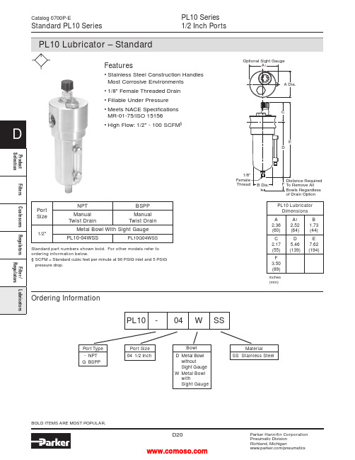
PL10 Series1/2 Inch PortsCatalog 0700P-EStandard PL10 Seriesof Drain Option Ordering InformationPort Type- NPTG BSPPPort Size04 1/2 InchMaterialSS Stainless SteelPL10 - 04 W SSBOLD ITEMS ARE MOST POPULAR.PL10 LubricatorDimensionsA2.36(60)A12.52(64)B1.73(44)C2.17(55)D5.46(139)E7.62(194)F3.50(89)inches(mm)Features• Stainless Steel Construction HandlesMost Corrosive Environments• 1/8" Female Threaded Drain• Fillable Under Pressure• Meets NACE SpecificationsMR-01-75/ISO 15156• High Flow: 1/2" - 100 SCFM§BowlD Metal BowlwithoutSight GaugeW Metal BowlwithSight GaugePortSizeNPT BSPPManualTwist DrainManualTwist Drain1/2"Metal Bowl With Sight GaugePL10-04WSS PL10G04WSSStandard part numbers shown bold. For other models refer toordering information below.§ SCFM = Standard cubic feet per minute at 90 PSIG inlet and 5 PSIGpressure drop.012345P r e s s u r e D r o p - P S I GP r e s s u r e D r o p - b a r.1.2.3Primary Pressure - PSIG1.7 bar3.4 bar 5.2 bar 6.9 barPrimary Pressure - bar051015202530354045Flow - dm /s3nPL10 SeriesAir Line LubricatorsCatalog 0700P-E Technical Specifications – PL10PL10 Filter Kits & AccessoriesDrain Kit –Manual Twist Drain –Small (Old) ..........................................................SA600Y7-1SS Large (New) ...............................................................SAP05481 Pipe Nipple –1/2" 316 Stainless Steel ................................................616A28-SS Sight Dome Kit –(Old)..................................................................................RKL10SS (New) ..................................................................................PS740NSpecificationsBowl Capacity ..................................................................4.0 OuncesPort Threads ..........................................................................1/2 Inch Pressure & Temperature Ratings –Metal Bowl (D) ...................................0 to 300 PSIG (0 to 20.7 bar) 0°F to 150°F (-18°C to 66°C) Metal Bowl (W) ..................................0 to 250 PSIG (0 to 17.2 bar) 0°F to 150°F (-18°C to 66°C)Note: Air must be dry enough to avoid ice formation attemperatures below 32°F (0°C).OperationAir flowing through the unit goes through two paths. At low flow rates the majority of the air flows through the Venturi section (A). The rest of the air opens the check valve (C). The velocity of the air flowing through the Venturi section (A) creates a pressure drop. This lower pressure allows the oil to be forced from the reservoir through the pickup tube (B) and travels up to the metering screw (D). The rate of oil delivery is then controlled by adjusting the metering screw (D). Oil flows past the metering screw (D) and forms a drop in the nozzle tube (E). As the oil drops through the dome (F) and back into the Venturi section (A), it is broken up into fine particles. It is then mixed with the air flowing past the check valve (C) and is carried downstream. As the air flow increases the check valve (C) will open more fully. This additional flow will assure that the oil delivery rate will increase linearly with the increase of air flow.Technical InformationWeight ........................................................................1.9 lb. (0.85 kg)Materials of ConstructionBody .....................................................................316 Stainless Steel Bowl .....................................................................316 Stainless Steel Dip Tube ...............................................................316 Stainless Steel Drain ....................................................................316 Stainless Steel Fill Plug ................................................................316 Stainless Steel Seals .............................................................................Fluorocarbon Sight Dome ...............................................................................Nylon Sight Gauge ........................................................................Isoplast(Revised 11-21-12)Stainless Steel FRLs Catalog 0700P-ENotes。
EDIMAX N300 Wi-Fi多功能無線訊號延伸器 EW-7438RPn Mini說明書说明书

EW-7438RPn Mini 是專為延伸跨樓層、多房間的無線Wi-Fi 訊號所設計的多功能迷你無線訊號延伸器,它能延伸家中現有的無線網路、有效減少訊號死角,大幅提昇上網品質。
同樣具備三合一功能設計,不同於前一代EW-7834RPn V2設計, EW-7834RPn Mini 除了擁有更好的傳輸效能,它巧妙運用簡約美學的工業設計,將體積縮減16%,不僅不會干擾鄰座電源插孔的使用,且減少塑料使用,讓環境少ㄧ些負擔,同時EW-7438RPn Mini 更提供免費EdiRange App (適用於無線訊號延伸模式Wi-Fi Extender Mode 下),無論 iOS 或Android 都適用,讓您能輕鬆操作和管理如無線排程及訪客網路等功能,化繁為簡的設計,省空間省體積但絕不會省效能。
EW-7438RPn Mini 萬用相容的設計,可適用各家廠牌的無線分享器,而挑戰全台最簡易的安裝設定方式和最方便的使用方式,EW-7438RPn Mini 更是當之無愧,不僅同時具備可快速與上層無線分享器連線的WPS 按鍵,也提供獨家iQ Setup 超簡易設定方式,讓找不到分享器WPS 按鍵的朋友(如使用中華電信所提供的家用無線路由器)也能安心輕鬆完成安裝連線。
延續前一代EW-7834RPn Mini 設計,EW-7438RPn Mini 不僅可做Wi-Fi 訊號延伸,還可當做AP(將有線訊號轉為無線訊號)或AP Client(將無線訊號轉為有線訊號)來使用,多功能設計優化您家中的無線環境,讓您隨時都能享受穩定、高品質的無線網路。
訊號強度指示燈設計,幫您找到最佳架 設地點, 優化Wi-Fi 覆蓋率© EDIMAX Technology Co., Ltd. All Rights Reserved.•獨家開發,唯一專為中華電信所提供家用無線分享器所設計的 iQSetup 快速設定•無線訊號延伸模式支援手機APP 管理,具備晚安模式,可夜間關機,次日早上自動啟動內建電源插頭,體積輕巧,易於安裝訊號強度指示燈N300 Wi-Fi 多功能無線訊號延伸器N300 Multi-function Wi-Fi Extender with EdiRange AppEW-7834RPn Mini2) iQ Setup 超簡易設定 :找不到分享器的WPS 按鍵,沒關係!只要使用iQ Setup ,不管家裏是哪個牌子的無線分享器,通通都能連,而且透過智慧型手機就可以設定,不開電腦也行。
nep988-400V说明书
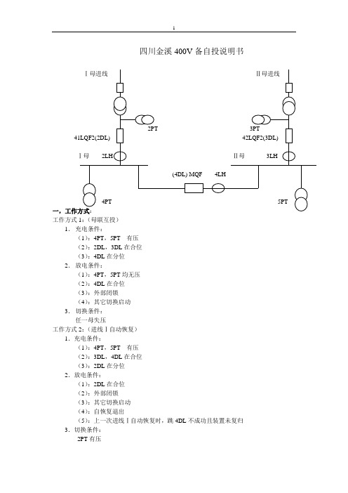
四川金溪400V备自投说明书工作方式1:(母联互投)1.充电条件:(1):4PT,5PT有压(2):2DL,3DL在合位(3):4DL在分位2.放电条件:(1):4PT,5PT均无压(2):4DL在合位(3):外部闭锁(4):其它切换启动3.切换条件:任一母失压工作方式2:(进线Ⅰ自动恢复)1.充电条件:(1):4PT,5PT有压(2):3DL,4DL在合位(3):2DL在分位2.放电条件:(1):2DL在合位(2):外部闭锁(3):其它切换启动(4):自恢复退出(5):上一次进线Ⅰ自动恢复时,跳4DL不成功且装置未复归3.切换条件:2PT有压工作方式3:(进线Ⅱ自动恢复)1.充电条件:(1):4PT,5PT有压(2):2DL,4DL在合位(3):3DL在分位2.放电条件:(1):3DL在合位(2):外部闭锁(3):其它切换启动(4):自恢复退出(5):上一次进线Ⅱ自动恢复时,跳4DL不成功且装置未复归3.切换条件:3PT有压二,切换过程1.母联互投(Ⅰ母失压)(1):方式一充电完成(2):Ⅰ母失压(3):工作进线无流(2LH 小于无流定值)(4):备自投经整定的延时跳2DL,判断2DL位置接点,等待2DL跳开,合4DL。
(5):4DL合位后,备自投成功动作一次。
装置将有以下事件记录:母联备用进线Ⅰ、跳进线Ⅰ开关成功,合母联开关成功。
(6):如果跳2DL不成功(发跳开关指令后,2DL2秒内不在分位),备自投装置会自动记录:跳进线Ⅰ开关失败;如果合4DL不成功(发合闸指令后,4DL2秒不在合位),备自投装置会自动记录:合母联开关失败。
2.母联互投(Ⅱ母失压)(1):方式一充电完成(2):Ⅱ母失压(3):工作进线无流(3LH 小于无流定值)(4):备自投经整定的延时跳3DL,判断3DL位置接点,等待3DL跳开,合4DL。
(5):4DL合位后,备自投成功动作一次。
装置将有以下事件记录:母联备用进线Ⅱ、跳进线Ⅱ开关成功,合母联开关成功。
Micrel SY89856U 2GHz 低功耗 1 6 LVPECL 分率缓冲器说明书

SY89856U2GHz, Low-Power, 1:6 LVPECL Fanout Buffer with 2:1 Input MUX and Internal TerminationGeneral DescriptionThe SY89856U is a 2.5V/3.3V precision, high-speed, 1:6 fanout capable of handling clocks up to 2.0GHz. A differential 2:1 MUX input is included for redundant clock switchover applications.The differential input includes Micrel’s unique, 3-pin input termination architecture that allows the device to interface to any differential signal (AC- or DC-coupled) as small as 100mV (200mV pp) without any level shifting or termination resistor networks in the signal path. The outputs are LVPECL (100k, temperature compensated), with extremely fast rise/fall times guaranteed to be less than 200ps.The SY89856U operates from a 2.5V ±5% supply or a 3.3V ±10% supply and is guaranteed over the full industrial temperature range of –40°C to +85°C. The SY89856U is part of Micrel’s high-speed, Precision Edge® product line. Datasheets and support documentation are available on Micrel’s web site at: . Features∙ 6 ultra-low skew copies of the selected input∙2:1 MUX input included for clock switchover applications ∙Low power: 225mW typical (2.5V)∙ 2.5V to 3.3V supply voltage∙Unique input isolation design minimizes crosstalk∙Guaranteed AC performance over temperature and voltage:-Clock frequency range: DC to >2.0GHz-<400ps IN-to-OUT t pd-<200ps t r/t f times-<30ps skew (output-to-output)∙Ultra-low jitter design:-40fs RMS phase jitter-0.7ps RMS crosstalk-induced jitter∙Unique input termination and VT pin accepts DC- and AC-coupled inputs (CML, PECL, LVDS)∙100k LVPECL compatible output swing∙–40°C to +85°C industrial temperature range∙Available in 32-pin (5mm x 5mm) QFN package Applications∙Redundant clock distribution∙All SONET/SDH clock/data distribution∙All Fibre Channel distribution∙All Gigabit Ethernet clock distributionMarkets∙LAN/WAN∙Enterprise servers∙ATE∙Test and measurementPrecision Edge is a registered trademark of Micrel, Inc.Ordering Information(1)Notes:1. Contact factory for die availability. Dice are guaranteed at T A = 25°C, DC Electricals only.2. Tape and Reel.Pin Configuration32-Pin QFNPin DescriptionLVPECL Output Interface ApplicationsFunctional Block DiagramAbsolute Maximum Ratings(3)Supply Voltage (V CC) .................................... –0.5V to +4.0V Input Voltage (V IN) ............................................ –0.5V to V CC LVPECL Output Current (I OUT)Continuous ............................................................ 50mA Surge .................................................................. 100mA Termination CurrentSource or sink current on V T............................. ±100mA V REF-AC Source or sink current………….................... ±2.0mA Lead Temperature (soldering, 20s) .......................... +260°C Storage Temperature (T s) ........................... –65°C to 150°C Operating Ratings(4)Supply Voltage (V CC) ............................ +2.375V to +2.625V ............................................................... +3.0V to +3.6V Ambient Temperature (T A) .......................... –40°C to +85°C Package Thermal Resistance(5)QFN (θJA)Still-Air ............................................................... 35°C/W QFN (ψJB)Junction-to-Board .............................................. 16°C/WDC Electrical Characteristics(6)T A = –40°C to +85°C, unless otherwise noted.Notes:3. Permanent device damage may occur if absolute maximum ratings are exceeded. This is a stress rating only and functional operation is not impliedat conditions other than those detailed in the operational sections of this data sheet. Exposure to absolute maximum ratings for extended periods may affect device reliability.4. The datasheet limits are not guaranteed if the device is operated beyond the operating ratings.5. Package thermal resistance assumes exposed pad is soldered (or equivalent) to the device’s most negative potential on the PCB. θJA and ψJB valuesare determined for a 4-layer board in still air, unless otherwise stated.6. The circuit is designed to meet the DC specifications shown in the above table after thermal equilibrium has been established.7. V IH (min) not lower than 1.2V.LVPECL DC Electrical Characteristics(6)V CC = 2.5V ±5% or 3.3V ±10%; T A = –40°C to + 85°C; R L = 50Ω to V CC– 2V, unless otherwise noted.LVTTL/CMOS DC Electrical Characteristics(6)V CC = 2.5V ±5% or 3.3V ±10%; T A = –40°C to + 85°C, unless otherwise noted.AC Electrical Characteristics(8)V CC = 2.5V ±5% or 3.3V ±10%; T A = –40°C to + 85°C, unless otherwise noted.Notes:8. High-frequency AC-parameters are guaranteed by design and characterization.9. Output-to-output skew is measured between outputs under identical input conditions.10. Part-to-part skew is defined for two parts with identical power supply voltages at the same temperature and with no skew of the edges at therespective inputs.11. Crosstalk is measured at the output while applying two similar differential clock frequencies that are asynchronous with respect to each other at theinputs.Typical CharacteristicsV CC = 3.3V, GND = 0V, V IN≥ 400mV, t r/t f≤ 300ps, T A = 25°C, unless otherwise noted.Functional CharacteristicsV CC = 3.3V, GND = 0V, V IN≥ 400mV, t r/t f≤ 300ps, T A = 25°C, unless otherwise stated.Singled-Ended and Differential SwingsFigure 1. Single-Ended Voltage Swing Figure 2. Differential Voltage Swing Timing DiagramsOct. 1, 201311Revision 3.1****************** or (408) 955-1690Input and Output StagesFigure 3. Simplified DifferentialFigure 4. Simplified LVPECL Output StageInput Interface ApplicationsFigure 5. DC-Coupled LVPECLInput Interface Figure 6. AC-Coupled LVPECLInput Interface Figure 7. DC-Coupled CMLInput InterfaceFigure 8. AC-Coupled CMLInput InterfaceFigure 9. LVDS Input InterfaceOct. 1, 201312Revision 3.1****************** or (408) 955-1690LVPECL Output Interface ApplicationsLVPECL has a high input impedance and a very low output impedance (open emitter), and a small signal swing which results in low EMI. LVPECL is ideal for driving 50Ω and 100Ω-controlled impedance transmissionlines. There are several techniques for terminating the LVPECL output: parallel termination-Thevenin equivalent, parallel termination (3-resistor), and AC-coupled termination. Unused output pairs may be left floating. However, single-ended outputs must be terminated or balanced.Figure 10. Parallel Termination-Thevenin EquivalentNote:12. For 2.5V Systems: R1 = 250Ω, R2 = 62.5Ω.Figure 11. Parallel Termination (3-Resistors)Notes:13. Power-saving alternative to Thevenin termination.14. Place termination resistors as close to destination inputs as possible. 15. R b resistor sets the DC bias voltage, equal to V T . 16. For 2.5V systems, R b = 19Ω.Related DocumentationPackage Information(17)32-Pin QFN (QFN-32)Note:17. Package information is correct as of the publication date. For updates and most current information, go to .MICREL, INC. 2180 FORTUNE DRIVE SAN JOSE, CA 95131 USATEL +1 (408) 944-0800 FAX +1 (408) 474-1000 WEB Micrel makes no representations or warranties with respect to the accuracy or completeness of the information furnished in this data sheet. This information is not intended as a warranty and Micrel does not assume responsibility for its use. Micrel reserves the right to change circuitry, specifications and descriptions at any time without notice. No license, whether express, implied, arising by estoppel or otherwise, to any intellectual property rights is granted by this document. Except as provided in Micrel’s terms and conditions of sale for such products, Micrel assumes no liability whatsoever, and Micrel disclaims any express or implied warranty relating to the sale and/or use of Micrel products including liability or warranties relating to fitness for a particular purpose, merchantability, or infringement of any patent, copyright or other intellectual property right.Micrel Products are not designed or authorized for use as components in life support appliances, devices or systems where malfunction of a product can reasonably be expected to result in personal injury. Life support devices or systems are devices or systems that (a) are intended for surgical implant into the body or (b) support or sustain life, and whose failure to perform can be reasonably expected to result in a significant injury to the user. A Purchaser’s use or sale of Micrel Products for use in life support appliances, devices or systems is a Purchaser’s own risk and Purchaser agrees to fullyindemnify Micrel for any damages resulting from such use or sale.© 2005 Micrel, Incorporated.Oct. 1, 2013 13 Revision 3.1****************** or (408) 955-1690。
NEPSI MSP 中文名:NEPSI 中央电源设备有限公司的中央电源保护设备说明书
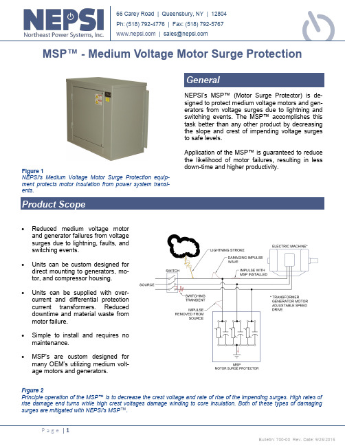
66 Carey Road | Queensbury, NY | 12804 Ph: (518) 792-4776 | Fax: (518) 792-5767 |***************NEPSI's MSP™ (Motor Surge Protector) is de-signed to protect medium voltage motors and gen-erators from voltage surges due to lightning and switching events. The MSP™ accomplishes this task better than any other product by decreasing the slope and crest of impending voltage surges to safe levels.Application of the MSP™ is guaranteed to reduce the likelihood of motor failures, resulting in less down -time and higher productivity.GeneralMSP™ - Medium Voltage Motor Surge ProtectionFigure 1NEPSI's Medium VoltageMotor Surge Protection equip-ment protects motor insulation from power system transi-ents.Figure 2Principle operation of the MSP™ is to decrease the crest voltage and rate of rise of the impending surges. High rates of rise damage end turns while high crest voltages damage winding to core insulation. Both of these types of damaging surges are mitigated with NEPSI's MSP ™.∙Reduced medium voltage motor and generator failures from voltage surges due to lightning, faults, and switching events.∙Units can be custom designed for direct mounting to generators, mo-tor, and compressor housing.∙Units can be supplied with over -current and differential protection current transformers. Reduced downtime and material waste from motor failure.∙Simple to install andrequires no maintenance.∙MSP's are custom designed for many OEM’s utilizing medium volt-age motors and generators.Due to the wavelength and travel time of lightning and switching transients, the MSP™ is most effec-tive when placed as close as practical to the motor terminals with the ground leads being as short as possible. This will limit the surge voltage seen by the motor to the discharge voltage of the arrester. For best protection, one MSP™ should be placed at each medium voltage motor or generator. Where there are many small motors or explosion proof mo-tors in hazardous locations, a single MSP™ at the motor control center is recommended.The proper choice of MSP™ is based on the system and/or motor voltage and the system grounding. The order guide below can be used to determine the cor-rect MSP™ for your application.Enclosure11 gauge galvanneal steel all welded construction, C2 structural steel channel base, bolted stainless steel hinged door. NEMA 1, 3R, 4X (optional), 12 | IEC IP10, IP14, IP56, IP52, NEC Class 1 & 2, Div. II designs also available.Surge CapacitorThe MSP™is equipped with hermetically sealed low-loss, low-inductance surge capacitors. Their capacitance rating is based upon the MSP™ voltage rating as shown in Table 1 below. The surge capacitor is equipped with discharge resistors that reduce the residual voltage on the capacitor to 50 volts in 5 minutes.Wall mounting flangesAllows the MSP™ to be mounted on suitable walls.Surge/Lightning ArrestersThe MSP™is equipped with heavy duty, silicone rubber housed MOV distribution class lightning arresters incorpo-rating the latest in metal oxide varistor (MOV) design tech-niques (Station Class are available as an option). The high track resistant, non-fragmenting silicone rubber housed arrester provides increased safety for personnel and equipment. The lightning arresters complies with the latest revision of ANSI/IEEE C62.11 "IEEE Standard for Metal Oxide Surge Arresters for AC Power Circuits.TerminalsThe MSP is provided with a Copper NEMA 2-hole pad for interconnection with customer wiring.Operating Temperature-40F (-40C) to +115F (+46C)Warranty1 year replacement parts per NEPSI’s Standard Warranty.FusesIncreases system and equipment reliability by re-moving a failed MSP™. Blown fuse detection is provide through a set of dry contacts to alert plan personnel of a blown fuse.Pecker-Head/Motor Terminal MountingThe MSP™ can be custom designed for direct mounting to a motor or generator to act as a termi-nal box. The equipment can be equipped with a neutral grounding resistor, differential CT’s, and ground CT to provide all fault sensing.Differential current transformersThis option is shown in Figure 3, below. The differen-tial CT’s are placed inside the MSP™ and afford the highest level of protection for the motor or generator.MSP™ Ordering GuideThe MSP ™ can be ordered by choosing the part number from the table below based on the system voltage and type of grounding. Options are ordered by adding part number suffixes.Table 1MSP ™ Standard Part NumbersFigure 3Three -line diagram of MSP™ equipped with differential current transformers and phase overcurrent transformers for connection to motor protection relays.Figure 4Approximate Layout for basic MSP ™. Layout and dimensions may change without notice. Confirm layout and dimensions at order placement.Table 3MSP Dimensions Weights and Electrical ValuesTable 2MSP Part Suffixesmary current rating of the CT where #### appears.For example, an MSP ™ for a 500 HP motor that is on a 4.16kV resistive grounded system with the wall mounting brackets would have the following part number: MSP6A0416Contact the factory or your nearest sales representa-tive for options and voltages not shown above.。
NEP998A继电保护装置在高压电动机中的应用
NEP998A继电保护装置在高压电动机中的应用【摘要】在电力生产中,电气设备举足轻重,它的可靠运行对于生产安全来说非常关键,而电动机保护设备又是电动机可靠平稳运行的主要保障,本文结合陡河发电厂6KV电机保护,对NEP998A数字式继电保护装置在电力生产中的作用。
【关键字】保护装置;电机保护;电流前言:高压电机在工业生产中应用广泛,为避免电机因故障造成损坏,继电保护装置必不可少的,继电保护人员对保护的可靠性、快速性、灵敏性也越来越重视。
随着科学技术的不断发展,原老式的电磁型继电器保护已经逐渐被微机综保所替代,技术也逐渐成熟。
NEP998A型数字式继电保护装置在陡河发电厂6KV电机开关保护中广泛应用,在安全生产中起到了重要作用。
NEP998A型数字式继电保护装置,需要220V直流电源供电,采用高速处理器,主频220HZ,外围电路设计简单;测量三相电流和零序电流(Ia,Ib,Ic,Io),三相或线电压(Uan,Ubn,Ucn,Uab,Ubc,Uca);保护元件的出口方式可通过跳闸矩阵进行整定,所有继电器出口节点可选择为跳闸接点(自动返回)或信号接点(复归后返回)。
保护功能及原理说明(1)电流速断保护它能在最短的时间内迅速切除短路故障,减小故障持续时间,防止事故扩大。
异步电动机启动过程中电流很大,能达到5-8倍额定电流(Ie),启动时间能达到几十秒。
当任一项电流大于速断保护电流定值时,保护动作。
该保护设有“起动中速断定值”和“起动后速断定值”,起动中采用前者,按躲过电动机起动电流整定,起动结束后采用后者,按电动机自起动电流和区外出口短路时电动机最大反馈电流考虑,取电流大者。
(2)过流保护当任一相电流大于过流保护定值时,经可设定的延时时间,保护动作,动作电流一般为(1。
2-2)Ie,延时按躲过电动机起动时间整定。
此电流值小于速断保护的定值。
(3)过负荷保护由于短时过负荷不会引起系统或电力设备的安全问题,但长时间会引起系统或电力设备本身的安全或稳定问题,或用电设备的安全,故过负荷一般保护延时作用于信号和跳闸。
[整理]YD988X说明书多参数.
![[整理]YD988X说明书多参数.](https://img.taocdn.com/s3/m/827dd0067e21af45b307a8ac.png)
第一章技术指标1.1一般规定使用本仪器之前,请先了解本仪器所使用的相关安规标志,以保证安全。
在开启本仪器电源之前,请先选择正确输入电压源(110/220V AC)规格及正确的输入保险丝。
2.2.2.功能键盘区2.2.2.1泄漏电流按键YD9881用于进入泄漏电流测试状态,并读出该组别该参数下的设置参数。
YD9880用于将最后一次连接测试的结果列表显示在液晶屏上。
2.2.2.2组别按键用于记忆组的选择,可以从50组记忆组之中任意选择一组执行测试。
每个组别可设定4-7(不同机型)种测试参数,并以最后选择的参数作为测试用。
可以使用该键选择其中任意一个组别后,读出或设定该组别的测试参数。
2.2.2.3锁定按键用于键盘锁定,当在锁定状态关机后,下次开机仍保留其锁定状态,具体操作参看本书密码设定部分。
2.2.2.4系统按键用于进入系统设定状态,内含蜂鸣器,连接测试,密码输入,远控,RS232,接地时显示电阻或电压等选择控制,具体操作参看本书系统参数设置部分。
2.2.2.5交流耐压选择键用于进入交流耐压状态,并读出该组别该参数下的设置参数。
2.2.2.6直流耐压选择键用于进入直流耐压状态,并读出该组别该参数下的设置参数。
2.2.2.7绝缘电阻选择键用于进入绝缘电阻状态,并读出该组别该参数下的设置参数。
2.2.2.8接地电阻按选择键用于进入接地电阻状态,并读出该组别该参数下的设置参数。
2.2.2.9启动测试状态选择键启动测试状态选择键与数字键“7”复用,用于进入启动测试状态,并读出该组别该参数下的设置参数。
2.2.2.10功率测试状态选择键功率测试状态选择键与数字键“8”复用,用于进入功率测试状态, 并读出该组别该参数下的设置参数。
2.2.2.11设置按键用于进入各状态下各项参数的设置状态。
2.2.2.12∧和∨按键用于各项参数设置时的项目选择,或在测试时输出电压增加或减少(仅在耐压测试状态有效,每次约增加或减少10V)。
深圳市多恩技术有限公司2022产品手册说明书

S H I F T T O S A F E T Y安全/传感/控制2022产品手册Products and ServicesS h e n z h e n T o r e n t T e c h n o l o g y C o.,L t d.深圳市多恩技术有限公司0755********1. 功能安全控制器及传感器,产品最高可达PLe/SiL3安全性能等级,符合中国及全球标准,通过欧美专业机构和中国国家检测中心认证,应用于自动化设备,AGV,物流系统,数控机床,电梯,机器人,风电等诸多行业;2. 提供专业的自动化产线整体安全防护系统风险评估,设计与定制。
一站式交钥匙工程,最高符合PLe/SiL3安全性能等级,快速实现安全智能连接。
多恩技术是专业的安全传感控制研发企业,具备TUV 认证的机械安全风险评估资质,同时也是中国机械工业安全卫生协会会员单位,公司产品具有多项发明及实用新型专利,并获得多家国内国际权威机构认证。
Profile公司简介产品与服务P&S技术与荣誉Honor多恩技术是专注于工业安全控制与传感技术的研发型企业,由曾任职于世界100强工业电气巨头的海归工程师团队创建,具备电子、电气、机械核心研发能力,团队70%以上为十年以上工业行业经验的研发人员。
我们 的目标是让产品功能及应用精益求精,解决工业生产的安全难题,把安全的基因更加广泛植入到国内的传感与控制系统中,推动工业4.0的战略早日实现。
引言CONENT 目录0102040607081012141516171820多功能安全继电器功能型安全继电器可配置安全继电器佰安翼AnEZ 电磁式安全联锁开关截留钥匙型安全开关门栓把手部件安全触边/地毯安全围栏安全控制系统Safety V+可视化监视系统安全评估与改造行业应用引言01切割事故会造成严重的后果,比如人员伤亡,设备受损,生产停滞,经济赔偿,行政处罚,法务支出,额外的事故处理人力及费用,企业名誉受损等。
- 1、下载文档前请自行甄别文档内容的完整性,平台不提供额外的编辑、内容补充、找答案等附加服务。
- 2、"仅部分预览"的文档,不可在线预览部分如存在完整性等问题,可反馈申请退款(可完整预览的文档不适用该条件!)。
- 3、如文档侵犯您的权益,请联系客服反馈,我们会尽快为您处理(人工客服工作时间:9:00-18:30)。
N E P988说明书(总32页) -CAL-FENGHAI.-(YICAI)-Company One1-CAL-本页仅作为文档封面,使用请直接删除NEP988数字式备用电源自动投切装置说明书国电南京自动化股份有限公司NEP 988数字式备用电源自动投切装置说明书编写:黄作兵审核:陈雪峰批准:郭效军国电南京自动化股份有限公司二OO三年五月目次1 装置概述........................................................................................................... 错误!未定义书签。
2 主要技术指标................................................................................................... 错误!未定义书签。
3功能介绍........................................................................................................... 错误!未定义书签。
NEP988A母联备自投功能说明 ........................................................................ 错误!未定义书签。
NEP988B进线互投功能说明 ............................................................................ 错误!未定义书签。
NEP988C内桥开关备自投功能说明 ................................................................ 错误!未定义书签。
NEP988D厂用电源备自投 ................................................................................ 错误!未定义书签。
NEP988E水电厂备自投..................................................................................... 错误!未定义书签。
4 操作说明........................................................................................................... 错误!未定义书签。
键盘排列及显示 ................................................................................................. 错误!未定义书签。
键的功能 ............................................................................................................. 错误!未定义书签。
液晶显示及键盘操作说明 ................................................................................. 错误!未定义书签。
5 订货须知........................................................................................................... 错误!未定义书签。
6 附图................................................................................................................... 错误!未定义书签。
1 装置概述NEP 988数字式备用电源自动投切装置是在消化吸收国内外先进经验的基础上专门为发电厂、变电站开发(可与各类综合自动化配套)的产品。
该类产品将结构小巧,可在恶劣的工业环境下(如高、低温、震动、有害气体、灰尘、强电磁干扰等)长期可靠地运行。
产品可按功能就地安装,并具有远传、记忆各种操作或故障信息等功能,同时亦提供独立的中央信号空接点。
特点:●采用Motorola高性能32位单片机。
●采用一对一的方式,调试、安装及维护均非常便利。
●人机界面友好,液晶中文显示。
显示信息丰富、直观、各种操作亦非常方便。
●完善的自我诊断功能,不需人为干预,故障可定位到某集成块。
●最近100条事件记录(记录事件时间和类型)、10条事故记录(包含故障前360毫秒,故障后600毫秒,记录事故时间、类型、定值、控制字、交流量幅值及采样点)及200条遥信变位信息(记录遥信变位时间和类型),方便分析。
●高抗干扰性能,能满足:GB/T 快速瞬变干扰试验Ⅳ级GB/T 脉冲群干扰试验Ⅲ级GB/T 静电放电干扰试验Ⅲ级功能:母联备自投、进线互投、内桥开关备自投、厂用电源自投、水电厂备自投、两相三段式电流保护、过流加速段保护及各种开关量变位信息等功能。
NEP 988型备用电源自动投切装置分为5种配置2 主要技术指标直流额定电压:DC220V(110V)允许偏差 -20%~+15%交流额定电压、电流:100V(57V)、5A(1A)各参数整定范围:(详见装置整定值清单)电流元件:0.01A~100A 级差:0.01A电压元件:~150V 级差:时间:0~60s 级差:功耗:交流< VA/相直流<6W(正常工作)绝缘性能:能承受GB/T 7261-2000规定的各回路对地耐压2000V,历时1分钟及5kV冲击电压试验抗电磁干扰性能:能承受GB/T 辐射电磁场干扰试验Ⅲ级能承受GB/T 快速瞬变干扰试验Ⅳ级能承受GB/T 脉冲群干扰试验Ⅲ级能承受GB/T 静电放电干扰试验Ⅲ级机械性能:能承受GB/T 11287-2000规定的严酷等级为一级的振动响应试验能承受GB/T 11287-2000规定的严酷等级为一级的振动耐久试验能承受GB/T 14537-1993规定的严酷等级为一级的冲击响应试验能承受GB/T 14537-1993规定的严酷等级为一级的冲击耐久试验能承受GB/T 14537-1993规定的严酷等级为一级的碰撞试验环境条件保存温度:-40℃~ +70℃工作温度:-25℃~+60℃(注:特殊要求时可达-40℃~+70℃,液晶例外)相对湿度:5%~95%大气压力:86KPa~106KPa外形尺寸:参见附图3功能介绍(所有保护均可由标志字投退)NEP988A 母联备自投功能说明(图3-1)3.1.1 自投方式一1)正常运行时,两段母线分列运行,两台变压器各带一段母线。
当某一进线电源故障或因其它原因被断开,分段开关应自动投入,且只允许动作一次。
2)进线开关手动跳闸,或装置未充电,或有外部闭锁时,分段开关应不自动投入。
3)充电条件:Ⅰ母Ⅱ母均三相有压,1ZKK、2ZKK在合位,3ZKK在分位。
充电条件满足15S后完成充电,备自投准备好。
放电条件:Ⅰ母Ⅱ母均三相无压或3ZKK在合位或有外部闭锁开入量。
放电条件满足后瞬时完成放电,备自投未准备好。
4)母联备用#1进线开关(3ZKK备用1ZKK)Ⅰ母无压,Ⅱ母有压则经延时跳1ZKK,确认1ZKK跳开后(1ZKK在跳位且1LH无流),合3ZKK。
5)母联备用#2进线开关(3ZKK备用2ZKK)Ⅱ母无压,Ⅰ母有压则经延时跳2ZKK,确认2ZKK跳开后(2ZKK在跳位且2LH无流),合3ZKK。
6)两相三段式电流保护:Ia > Izd 或 Ic > Izd 经整定的延时跳闸7)过流加速段保护:母联开关合上后在整定的后加速有效时间内监视流过母联开关的电流,若Ia > Izd 或Ic > Izd 经整定的延时跳闸。
否则在整定的后加速有效时间后,后加速段自动退出。
8)PT断线告警:装置判断出PT断线经延时10秒发PT断线信号图3-13.1.2 自投方式二1)正常运行时,#1(#2)进线带两段母线,#2(#1)进线因故障停电。
1ZKK(2ZKK)、3ZKK在合位,2ZKK(1ZKK)在分位。
当#2(#1)进线电源恢复时,跳3ZKK,合2ZKK(1ZKK)。
2)充电条件:Ⅰ母Ⅱ母均三相有压,1ZKK(2ZKK)、3ZKK在合位,2ZKK(1ZKK)在分位。
充电条件满足15S后完成充电,备自投准备好。
放电条件:Ⅰ母Ⅱ母均三相无压或2ZKK(1ZKK)在合位或有外部闭锁开入量。
放电条件满足后瞬时完成放电,备自投未准备好。
3)#1进线电源自动恢复Ux1有压则经延时跳3ZKK,确认3ZKK跳开后,合1ZKK。
4)#2进线电源自动恢复Ux2有压则经延时跳3ZKK,确认3ZKK跳开后,合2ZKK。
NEP 988B进线互投功能说明(图3-2)图3-23.2.1 正常运行时,#1(#2)进线带工作母线,#2(#1)进线作备用。
1ZKK(2ZKK)在合位、2ZKK(1ZKK)在分位,2ZKK(1ZKK)作备用。
当#1(#2)进线电源故障或因其它原因被断开,#2(#1)进线开关应自动投入,且只允许动作一次。
3.2.2 进线开关手动跳闸,或装置未充电,或有外部闭锁时,备用进线开关应不自动投入。
3.2.3 充电条件:工作母线三相有压,#2(#1)线路有压。
1ZKK(2ZKK)在合位,2ZKK(1ZKK)在分位。
充电条件满足15S后完成充电,备自投准备好。
放电条件:2ZKK(1ZKK)在合位或#2(#1)线路无压或外部闭锁开入量。
放电条件满足后瞬时完成放电,备自投未准备好。
3.2.4 #2进线作备用(2ZKK备用1ZKK)工作母线无压、Ux2有压,则经延时跳1ZKK,确认1ZKK跳开后(1ZKK在跳位且1LH无流),合2ZKK。
3.2.5 #1进线作备用(1ZKK备用2ZKK)工作母线无压、Ux1有压,则经延时跳2ZKK,确认2ZKK跳开后(2ZKK在跳位且2LH无流),合1ZKK。
3.2.6 两相三段式电流保护:Ia > Izd 或 Ic > Izd 经整定的延时跳闸3.2.7 过流加速段保护:备用开关合上后在整定的后加速有效时间内监视流过备用开关的电流,若Ia > Izd 或Ic >Izd 经整定的延时跳闸。