MagicTunning V1.12操作手册
MagicTunning V1.65操作手册

帝彩液晶图像拼接系统MagicTunning控制软件使用说明书目录一、欢迎 (1)1. 版本说明 (1)2. 欢迎使用 (2)二、安装MagicTunning (3)1. 系统运行环境 (3)2. 安装MagicTunning (3)三、使用MagicTunning (6)1.基本概念 (6)●内置拼接器 (6)●屏幕地址(编号) (6)●屏幕序号(序号) (7)●预案 (7)●外置拼接器 (8)●矩阵 (8)2. 界面介绍 (9)3. 用户管理 (10)●改变登录状态 (10)●编辑用户 (10)●修改默认登录状态 (11)4. 配置系统 (13)●配置显示布局 (13)●屏幕设置 (14)●画面设置 (16)●系统设置 (17)●自动开关机设置 (18)●通信端口设置 (19)●解码单元设置 (20)5. 操作内置拼接器 (21)●选择操作对象 (21)●电源操作 (21)●拼接操作 (22)●切换信号源 (22)●切换4画面显示效果 (22)●调整色彩 (22)●自动调整 (23)●4:3调整 (24)●边框效果调整 (25)●内置漫游窗口 (26)6. 操作外置拼接器 (26)●设置外置拼接器 (26)●使用外置拼接器 (29)7. 操作矩阵 (36)●矩阵切换 (36)●文字叠加 (37)●输入描述 (39)●通道轮询和预案轮询 (40)●矩阵文件设置 (42)8. 预案 (43)●内置预案 (43)●外置预案 (44)●记录预案 (45)●预案的轮询 (45)9. 解码平台设置 (45)●为解码平台配置外置拼接器 (45)●设置解码平台IP (46)●设置解码对象 (46)10. 备份系统 (47)一、欢迎1.版本说明2012-10-21:V1.0,第一次发布;2.欢迎使用欢迎使用MagicTunning。
MagicTunning包含对我公司所有产品的控制,在您操作我公司系统产品前,请仔细阅读本说明书。
I-CUE 智能镜操作手册说明书

I-CUE INTELLIGENT MIRROR Operations ManualTable of ContentsProduct Overview pg1 Product Description pg 2 Operation pg 2 Unpacking the unit pg 3 Control and power cables pg 3 Connections pg 4 Mounting the unit pg 4 Operating the unit pg 6 Modes of Operation pg 7 Summary of Control pg 9 Troubleshooting pg 10 Technical overview pg 12 Technical specifications pg 13 Drawings pg 15 I-Cue Mirror and Broadway scroller combined pg 15 I-Cue Mirror used without a color scroller pg 15 I-Cue Intelligent Mirror Parts List pg 16 Product OverviewThe I-Cue Mirror is designed to give years of trouble free use, providing that it is r e g ularly maintained and is used in accordance with the instructions detailed in this manual. If you should experience any problems that fall outside of the scope of this manual, please contact the selling dealer for further details.If the selling dealer is unable to satisfy your servicing needs, please contact the following, for full factory service:ROTAD1330 30th StreetSuite GSan Diego CA, 92154Attn: Repair Department800-468-0114 x25Product DescriptionThe I-Cue Mirror is a motorized mirror attachment which mounts onto fixed position spotlights to achieve many of the effects traditionally only available with high priced intelligent moving lights The compact and stylish design is equally at home in a t h e atre, exhibition centre, shopping mall, or car showroom.The moving mirror accurately redirects a fixed position beam of light through a pan of 230˚ and a tilt of 57˚, making it a very cost-effective and space-saving option for illuminating multiple locations using just a single spotlight. As well as being compatible with most standard medium and narrow beam profile fixtures, the unit can also be used with a color scroller to provide moving color and daisy chained to other lantern accessories to combine moving light with dynamic color changing and gobo rotating effects.The I-Cue Mirror is designed to operate either on the USITT DMX512 (1990) protocol or in stand-alone mode.The DMX serial data system allows for the individual addressing of multiple units on one data cabling system. The unit is addressed by using the three push button switches and LED display.The unit equipped with a diagnostic section on the LED display showing Power, DMX signal and level presence.When operating in stand-alone mode, the I-Cue Mirror only requires a 24 VDC supply to operate.Note:The quantity of I-Cue Mirrors used and the maximum cable length per power supply output is dependent upon the size of PSU/splitter box used. Operation• Unpacking the Unit• Control and power cables• Connections• Mounting the unit• Operating the unit• Modes of operation•Troubleshooting•Technical overview•Technical specificationsUnpacking the unitThe I-Cue Mirror package comes with the following items:• I-Cue Mirror• Safety wire (supplied fitted)• User manualThe unit is shipped in a specially constructed shipping carton to provide protection to the unit. Carefully open the carton and remove the unit by grasping the support arm in the middle and lifting the unit vertically out of the carton. Next, carefully remove the rubber restraint band used to stabilize the mirror unit during shipment.Note:The packing material protects the fixture during shipment; always use it to transport the fixture.The front light shield had been designed so that it can act as a shipping support and must be repositioned before using the unit. Loosen the two M4 wing screws on the front of the unit and reposition the light shield by moving the shield downward to the position necessary to prevent light leaks depending on the beam angle and focusing.Control and power cablesThe I-Cue Mirror utilizes an XLR 4-pin cable system.In DMX mode, this is used to supply power and data transfer. Pins 1 and 4 are supply 24V DC power. Pins 2 and 3 supply USITT1990 DMX512 control protocol, with a ground/drain wire to the connector shell.For use in ‘Stand-alone’mode, the unit requires a suitable 24V DC connected to Pins 1 and 4, with a ground/drain wire to the connector shell (not required, but suggested). Damage will occur if power connections short to data or ground/shield connections. When assembling XLR 4-pin cables, heat shrink should be used on each individual pin to prevent short circuits. (See diagram on following page.)N o t e:It is very important to ensure that the drain wire from the cable shield is c o n nected to both the XLR connector cases.Pin #1234 ChassisFunctionGround (-ve)Control data minus (-)Control data plus (+)24 VDC (+ve)Cable shield/Drain wireMinimum Cable size2.50mm_ (14 AWG)0.35mm_ (22 AWG)0.35mm_ (22 AWG)2.50mm_ (14 AWG)0.25mm_ (24 AWG) Detail of connector wiring (typical)(Note: Cable length should not exceed more than 75 M (250’) with return line) ConnectionsCorrect connection of the units to the power supply will decrease the chances of units malfunctioning due to cabling problems. Please follow these basic rules:a) Use the correct and gauge type of cable and connectors.b) Keep cable runs as short as possible to reduce line loss.c) Always use a return cable for each run.This will ensure balanced DC power to all units that the line is correctlyt e r m i nated and that all units receive power if one link of the chain is faulty. The correct wiring between male and female connectors is ‘one to one’.Mounting the unitFor proper operation, the unit must be firmly attached to the light fixture it is mounted on. To achieve this, the mounting plate of the unit has two flat springs at the outer edge. The unit is designed to mount in the rear color frame slot of the ellipsoidal fixture.The back plate should be inserted in the rear color slot and gently pushed down until the unit is firmly seated in the bottom of the slot. The safety wire supplied with the f i x ture should then be attached as a means of secondary fixing.Input power and DMX should be brought to the unit by way of XLR-4 cable. If daisy chaining is desired, a XLR-4 cable should be run from the output connector on the unit to the next device in the chain.When DMX is first applied to the unit, it will go through a homing sequence, which will cause the mirror to momentarily move around.Note:If the rear slot is not available for mounting of the unit because of the use of a gel holder in this slot, the front slot may be used for mounting instead.I-Cue Mirror mounted on a lighting fixture.Ensure the safety wire is used as a means of secondary attachment.Control FunctionRED button Mode access and ‘Record’BLACK button Decrements the mode level, or value BLUE button Increments the mode level, or value3 digit display Displays modes, monitor, or blank display.Red ButtonBlack ButtonBlue Button3 digit DisplayOperating the unitAll the unit functions are accessed using the LED display and the three push-button switches on the left side panel.PUSH BUTTON OPERATION:The RED button is used to scroll through the different modes of operation, and the BLUE or BLACK buttons used to select the level, or value, in that mode. If any mode or value is changed, the last digit of the display will flash until the RED button is pushed to acknowledge (or record) the change.DISPLAY OPERATION:Power-up DisplayOn power-up, the display will show ‘ini’during the initialization sequence, and then show the DMX address.MONITOR DISPLAY:If left undisturbed for 5-7 seconds, the display will revert to ‘Monitor Mode’•The first vertical bar indicates that there is Power (24V DC) at the unit.•The second vertical bar indicates that there is Data (DMX) at the unit.•The horizontal bars indicate the data Signal Level (DMX) at the unit.(See also: ‘Tr o u b l e s h o o t i n g ’section of this manual)power datasignal levelDISPLAY BLANK:The display can be set to auto-blackout after short time. This is selected through the mode menu. (See later in this section)RESET:If the RED button is held down, and the BLUE buttonpressed, the unit will reset to the factory default settings.This feature is particularly useful when the units are usein many different configurations/shows.Modes of OperationEFFECTIVE (STAND-ALONE) MODEIn this mode, the unit can be used without a DMX control signal; only a 24v DC sup-ply is required. To use the stand-alone mode;• Connect a suitable 24V DC power supply to the unit.• Press the RED button to scroll through the menu until the display reads ‘At0’.• Press the BLUE button once, so that the display reads ‘At1’(Auto mode) and press the RED button.• Press the RED button to scroll through the menu until the display reads ‘Pn’. This accesses the mirror panning movement in the auto mode. Using the BLUE/BLACK buttons select the range of movement you require Pn0 – Pn7, continuous back & forth sweep Pn8, or mirror held at the centre position Pn9. Press the RED b u t t o n to store the pan value and change the display to ‘tL’, the mirror tilting movement in the auto mode.• Repeat the above process to set a tilt movement value.• When the desired effect is selected, press the RED buttonDMX CONTROL MODEIn this mode, the unit can be fully controlled using two or four DMX channels (see below). Acombined DMX and 24v DC supply cabling system is required in this system. Press the RED button to move between modes, and to record any changes made.DMX CHANNELADDRESS MODEThis mode is used to set the DMX start address in the range of 1-511 (2 channels,8 -bit resolution) and 1-509 (4 channels, 16-bit resolution).The display shows thec u r rent DMX address. (To alter the address, press BLUE or BLACK button once to increment/ decrement the value; hold down the BLUE or BLACK for fast increments/ decrements of the value.PAN / TILT MOVEMENT MODESThese modes allow the user to reverse the direction of the pan, tilt, or pan and tilt motion, when the configurations of the lighting fixture/mirror unit dictate. The display shows either the pan movement or the tilt movement (‘Pn’pan/ ‘tL’tilt) and the cur-rent direction (‘0’= normal/ ‘1’= reverse) of travel. (Press BLUE or BLACK button to switch directions, and the RED button to change modes.)DMX RESOLUTIONThis mode is used to set the movement resolution, or accuracy, of the unit. The unit operates either with two or four DMX control channels, or stand-alone mode (with no DMX control). The display shows the current DMX mode (‘rn0’= 8-bit or ‘rn1’= 16-bit resolution). (Press BLUE or BLACK to switch between modes.)DISPLAY MODEThis mode is used to switch the display on or off. This feature can be used to blank displays that may be an unwanted distraction. The display will re-activate when any button is pressed. The display shows the current display mode (‘dP0’= display off or ‘dP1’= display on),(Press BLUE or BLACK to switch between on and off.)DMX / AUTOMATIC MODEThis mode is used to select either DMX control or automatic (stand-alone) operation of the unit. The display shows the current mode (‘ A t0’= DMX control, or ‘ A t1’= a u t o matic mode). (Press BLUE or BLACK to switch between modes.)DMX channel address modePanmovement modeTilt movement modeDMX resolution modeDisplay modeDMX/Automatic modeSets the units DMX address.This mode allows the user to reverse the direction of the pan motion.This mode allows the user to reverse the direction of the tilt motion.Sets unit operating with 2or 4 DMX control c h a n nels, with 8 or 16-bit resolution.This mode is used to switch the display on or off.This mode allows the user to select to between DMX and Automatic modes.To alter the address,press BLUE or BLACK button once to increase or decrease the value;hold down the BLUE or BLACK for fast incre-ments/ decrements.To alter the mode, press BLUE or BLACK button once to switch between modes.To alter the mode, press BLUE or BLACK button once to switch between modes.To alter the mode, press BLUE or BLACK button once to switch between modes.To alter the mode, press BLUE or BLACK button once to switch between modes.To alter the mode, press BLUE or BLACK button once to switch between modes.The display shows the current DMX address.In the range of 1-511(2 channel, 8-bit resolution)In the range of 1-509(4 channel, 16-bit resolution).The display shows that the PAN movement is set for normal direction.The display shows that the PAN movement is set for reverse direction.The display shows that the TILT movement is set for normal direction.The display shows that the TILT movement is set for reverse direction.The display shows the unit is set for 8-bit resolution.The display shows the unit is set for 16-bit resolution.This shows that the display is set for auto-blanking.This shows that the display is set to be permanently on.The display shows that the unit is set for DMX control. The display shows that the unit is set for automatic operation.Summary of control functions:Note: - Press the RED button to move between modes, and to record any changes made.DEFAULT SETTINGS:‘Factory’default settingsIf the unit is reset, using the RED button (held down), and the BLUE button pressed for 2 Sec’s, the unit will revert to the factory default settings.The ‘Factory’default settings put the unit in its normal operating mode.DMX Address = 001Pan/tilt direction = NormalResolution = 8-bit Display = On DMX/Auto = DMX Display Flip = Normal‘USER’DEFAULT SETTINGSEach time the RED record button is pressed, the unit will save that change and these ‘user defaults’will take precedence on the next power cycle. These ‘User’defaults can be reset to the ‘factory’defaults using the method detailed above.TroubleshootingThe LED display aids in the troubleshooting of the system. These indicators are located on the on the side panel of each unit.The first vertical bar indicates that there is power (24VDC) at the unit.The second vertical bar indicates that there is data (DMX) at the unit.The horizontal bars indicate the data (DMX) signal level at the unit.Note:The signal level changes during normal operation of the unit, and is present during stand-alone operation. 1st bar = 25%, 2nd bar = 50% and 3rd bar = 75%.Note:A high percentage of problems are a direct result of poor cabling, corrupt DMX control signals, and lack of suitable signal termination.power datasignal levelSYMPTOMUnit does not respond to DMX control, but DMX display indicator is on.Unit does not respond to DMX, DMX display indicator is off.Units run at different speeds. Units have dim display indicators and run slowly. Display indicators appear OK but unit does not move. The tilt doesn’t respond to DMX.Mirror panning/tilting in opposite direction.The mirror vibrates in one place when it is supposed to move.POSSIBLE CAUSEUnit set to wrong or differentDMX address.Bad cable.No DMX at splitter/PSU.Cable lengths are too long.No cable return line.Overloading of chain orcable runs too long.PSU overloaded.Mechanical (or electrical)failure in the unit.16-bit mode setting when8-bit control is intended, orvice versa.Pan/tilt reverse switch withimproper setting.Broken motor cablePopped out motor connector.SOLUTIONCheck DMX addresssettings.Check cable and DMX runfrom the console.Check the cable length andconfiguration. Ensure there is acable return line in the system.Check voltage levels on lastunit. Should not be below20VDC.Turn unit on and off. Returnunit for repair.Check and reset.Check and reset.Contact distributor for serviceReconnect and checkTechnical overviewThe electronics card consists of four key components: L298 Motor driver (x 2), 75176 Transceiver, and a processor.The 75176 transceiver operates in the receive config-uration to convert serial protocol to a TTL level. All data relevant to the operation of the unit is stored onboard in ‘flash’memory.The majority of electronics problems are usually created by external factors such as shorted cables, etc. The 75176 transceivers are susceptible to damage if 24VDC is present on the DMX signal lines. Troubleshooting is a process of elimination. First, rule out the other field factors (i.e. faulty cables, power sources). If an electronics problem is suspected try replacing the electronics card first. If accuracy problems should occur, check for obvious mechanical problems. For technical advice and/ or parts, please contact your selling dealer or the offices listed in this manual.Dimensions:Weight:Resolution: Accuracy:Movement Speed:DMX Protocol:DMX Addressing: Working Voltage:Power Consumption:Connectors:Body Material:Body Color:Mounting Plate:Max. Ambient Temperature Cooling:European Approvals: North American Approvals:260 x 230 x 265 mm (10.25” x 9” x 10.5")1.6 Kg (3.5 lbs)8 or 16 bitPan(230º Max.)0.9º8-bit mode0.028º16-bit mode Tilt (57.3º Max.)0.225º8-bit mode0.028º16-bit mode0-100% pan (max)= 2 sec0-100% tilt (max)= 1 secUSITT DMX512 (1990)Digitally, via push buttons (3) and LED display 24 VDC (+/- 10%)17 watts0.7 ampsXLR-4 (male) in and XLR-4 (female) through SteelBlack powder coat(Other colors available, P.O.A.)Integral mounting plate, designed for use in any ellipsoidal fixture with a 160 mm (6.25") gel slot. 40º C (104º F)Convection (natural)PendingPendingTechnical SpecificationsSpecificationsDrawingsI-Cue Mirror and Color Scroller combined.I-Cue mirror used with a color scroller.I-Cue Intelligent Mirror Parts ListPart NumberIC-01 Mounting Plate Assembly205 81001 0000 IC-02 Broadway Mounting Bracket205 81002 0000 IC-03 XLR Connector Assembly205 81003 0000 IC-04 Stepper Motor Lead (each)205 81004 0000 IC-05 Safety Chain Assembly205 81005 0000 IC-06 Mirror/Mounting Bracket Assembly205 81006 0000 IC-07 Digital Control Card205 81007 0000 IC-08 Stepper Motor (each)205 81008 0000 IC-09 Mirror Back Plate205 81009 0000 IC-10 Front Light Shield Assembly205 8101 00000Please call Rosco or your local Rosco dealer for pricing and availability.Rosco Laboratories,I n c.52 Harbor View Ave., Stamford, CT06902(203) 708-8900 1 (800) ROSCO N Y FA X(203) 708-89191120 N. Citrus Ave., Hollywood, CA90038(323) 462-2233 1 (800)R O S C O L A FA X:(323) 462-3338Rosco Laboratories,L t d.1241 Denison St. #44, Markham, Ontario, Canada L3R 4B4(905) 475-1400 (888)R O S C O TO FA X:(905) 475-3351R o s c o l a b,L t d.Blanchard Works, Kangley Bridge Rd., Sydenham, London SE26 5AQ England (208) 659-2300 FAX: (208) 659-3153Rosco Iberica,S.A.C/ Del Oro 76A, Pol. Industrial Sur, 28770 Colmenar Viejo, Madrid, Spain (341) 846-3602 FA X:(341) 846-3634Rosco do Brasil Ltda.Rua Antonio De Barros, 827, São Paulo SP Brasil CEP03401-000Te l:( 011) 218-2865 FA X:( 011) 218-0193Rosco Australia Pty Ltd.42 Sawyer Lane, Artarmon 2064, New South Wales, A u s t r a l i a(02) 9906-6262 FAX: (02) 9906-3430。
EPM12V1 测试套件用户手册说明书

ContentsINTRODUCTION . . . . . . . . . . . . . . . . . . . . . . . . . . . . . . . . . . . . . . . . . . . . . . . . . . . . . . . . .3 IMPORTANT NOTICE . . . . . . . . . . . . . . . . . . . . . . . . . . . . . . . . . . . . . . . . . . . . . . . . . . . . . .3 DESCRIPTION . . . . . . . . . . . . . . . . . . . . . . . . . . . . . . . . . . . . . . . . . . . . . . . . . . . . . . . . . . . .3 SPECIFICATION . . . . . . . . . . . . . . . . . . . . . . . . . . . . . . . . . . . . . . . . . . . . . . . . . . . . . . . . . .4 TEST SET-UP . . . . . . . . . . . . . . . . . . . . . . . . . . . . . . . . . . . . . . . . . . . . . . . . . . . . . . . . . . . .4 OPERATION NOTES . . . . . . . . . . . . . . . . . . . . . . . . . . . . . . . . . . . . . . . . . . . . . . . . . . . . .5-6 TEST RESULTS . . . . . . . . . . . . . . . . . . . . . . . . . . . . . . . . . . . . . . . . . . . . . . . . . . . . . . . .7-8 SCHEMATIC . . . . . . . . . . . . . . . . . . . . . . . . . . . . . . . . . . . . . . . . . . . . . . . . . . . . . . . . . . . . .9 LA YOUT . . . . . . . . . . . . . . . . . . . . . . . . . . . . . . . . . . . . . . . . . . . . . . . . . . . . . . . . . . . . . . . . .9 COMPONENT LIST . . . . . . . . . . . . . . . . . . . . . . . . . . . . . . . . . . . . . . . . . . . . . . . . . . . . . . .9IntroductionThis document describes the operations of evaluation kits (EVK) concerning the Eaton’s EPM DC-DC non-isolated converter product . The EVK includes test points for all main points where probing is necessary for evaluation . The EVK supports many options for Eaton’s product configuration . Using these options, the user is allowed to test all desired electrical specifications . This guide describes the test configurations and typical equipment setup . The typical input and output waveforms are also presented .Important notice• Please read the product datasheet and EVK user guide before using the EVK .• Please do not remove the product from the EVK .• This product is an ESD sensitive component and should be tested in an ESD protected area .• The EVK is designed to operate in clean and dust-free office or laboratory . EVK Should be protected from sunlight and sources of heat, and making sure air is flowing across the tool . Please keep it away from vibration or strong electromagnetic fields generated by electrical equipment .• When connecting and disconnecting the power interface, please turn off the power supply to avoid accidental short circuits causing injury .• The power connection must avoid reverse voltage application .• During the test, the electrical rating should be kept within the range specified in the data sheet .DescriptionThis EVK supports user test electrical performance of Eaton’s DC-DC non-isolated converter part number EPM12V1-05R5-01R0P . Figure 1 shows the EPM12V1-EVK and function outline . This EVK is made up of the input and output connectors and the DC/DC converter .There are two additional functions, output voltage trim function and remote on/off function .Figure 1. EPM12V1-EVKFigure 2: Test set-up example T able 2- Pin configurationConnector Function Pin symbol DescriptionJ1Input terminal VIN GND Connect the VIN and GNDterminals to the DC power source respectively.J2Output terminal VO GND Connect the VO and GNDterminals to the (electronic) load.JP1Remote on/off control CTRL 5V GND Switch the module on or off through controlling CTRLsignal in positive logic or negative logic.JP2/JP5Input voltage measuring point +VIN GND Connect the +VIN and GNDterminals to the voltage meter.JP3Output ripple measuring point +VO GND Connect the +VO and GND terminals to the probe with short ground lead.JP4/JP6Output voltage measuring point +VO GND Connect the +VO and GND terminals to the voltage meter.SW1Voltage trim selector 1, 2, 3, 4, 5, 6Adjust the output voltage with a trim resistor. There is a DIP switch with six choices.SpecificationsTable 1 shows the EPM12V1-EVK general performance specifications . The EPM12V1-EVK can deliver up to 1 A of output current and with a wide DC input . The modules can achieve high efficiency up to 89 .5%, wide operation temperature from -40 °C to +82 °C, and has short circuit protection . Input range is from 3 V to 14 V , nominal input voltage is 12 V. When the input reaches 3 V , the converter should turn on . Please refer to the product data sheet for the detailed specifications EPM12V1 data sheet** Ripple & noise: measured with 20 MHz bandwidth and 0.1 uF ceramic capacitor.T able 1- General specificationsParameter Conditions Minimum Nominal MaximumUnit Input Input voltage31214VdcInput current Vin=nom, no load 15mAStart-up Iout=0% ~ 3VdcTest set-upOperation notes Output voltage trim function Using a resistor in parallel between TRIM and GND (Figure 3) can adjust the output voltage of the converter and the following formula can calculate the trim resistor of the correspond voltage . Rtrim (kΩ)10.7Figure 3: Voltage trim resistor diagram T able 3- Resistor value and switch position Output voltage Calculated Rtrim Option 5 V 1.3 kΩSW 1 : on 3.3 V 9.8 kΩSW 2 : on 2.5 V 20.2 kΩSW 3 : on 1.8 V 44.2 kΩSW 4: on 1.5 V 71.3 kΩSW 5 : on 1.2 V 150 kΩSW 6 : on Figure 4: 5 V trimming output example Refer to Table 3 for basic values of resistors and switch positions for a particular output voltage . Only one switch should be on at a time . Figure 4 is an example for trimming 5 V output voltage .Load regulation vs.load Accuracy vs.load Remote on/off functionThe EVK can switch the converter on or off by controlling the remote on/off signal in positive logic . If the status of ON/OFF is open or from 1 .6 V to 5 V , the converter will turn on . Otherwise, if the status of ON/OFF is short to ground or from 0 V to 0 .1 V , the converter will shut down .The remote control circuit on the EVK is shown below . There are CTRL and 5 V pins at connector JP1 . For example, whenCTRL is high level, the converter will shut down . When CTRL is low level, the converter will turn on .Figure 5: Remote on/off circuit diagramT able 4- Remote on/off conditionsCondition CTRL Q1DC-DC ON Low level OffDC-DC OFF High levelOnFigure 6: CNTL low level, DC-DC on Figure 7: CNTRL high level, DC-DC offE ciency vs.load Power dissipation vs.load Line regulation vs.load Test results Typical characteristcs Model number: EPM12V1-05R5-01R0P Condition: Vout=5 VEPM12V1 Evaluation kit user guideOutput ripple and noise Ch1: Output voltage (10 mV/div.) Time scale: (1 us/div.)Transient response (75%-100% load) Ch1: Input voltage (5 V/div.)Ch4: Output current (0.5 A/div)Time scale: (100 us/div.)Ch2: Output voltage (20 mV/div.)EVK set-up and operation wave formModel number: EPM12V1-05R5-01R0P Conditions: Ta=+25 °C, VIN=12 V , VO=5 V , IO=1 A (full load)This ΔT plus ambient should remain below the specified maximum operating temperature for the module (please refer to the EPM12V1 data sheet ) .Start-up Ch1: Input voltage (5 V/div.)Ch2: Output voltage (2 V/div.) Time scale: (10 ms/div.)Shut-downCh1: Input voltage (5 V/div.) Ch2: Output voltage (5 V/div.) Time scale: (10 ms/div.)Eaton Electronics Division 1000 Eaton Boulevard Cleveland, OH 44122United States Eaton .com/electronics © 2021 Eaton All Rights Reserved Printed in USA Eaton is a registered trademark.Schematic Component list (for EPM12V1-05R5-01R0P)LayoutTop layer Bottom layerDescription Qty Designator EPM12V1-05R5-01R0P 1Capacitor, X7R, 1210, 10UF±10%, 50V 4C3, C4, C8, C9Capacitor, X7R, 0805, 0.1UF±10%, 50V 1C14MOSFET, AO3442 (SOT-23), 100V, N-Channel 1Q1Resistor, 0805, 10KΩ, 1%1R1Resistor, 0805, 1.3KΩ, 1%1R2Resistor, 0805, 0Ω, 5%1R3Resistor, 0805, 9.76KΩ, 1%1R4Resistor, 0805, 0Ω, 5%1R5Resistor, 0805, 20KΩ, 1%1R6Resistor, 0805, 0Ω, 5%1R7Resistor, 0805, 12KΩ, 1%1R8Resistor, 0805, 31.6KΩ, 1%1R9Resistor, 0805, 68KΩ, 1%1R10Resistor, 0805, 2.55KΩ, 1%1R11Resistor, 0805, 150KΩ, 1%1R12Resistor, 0805, 470Ω, 1%1R13Capacitor, 220UF/200V, KXJ series, 12.5x25 mm 1C1Terminal Block, 2P , pitch: 5.0mm 2J1, J2DIP Switch, six choices 1SW1Pin Header, single row, 14.2mm, 4P 1JP1Pin Header, single row, 14.2mm, 2P 5JP2, JP3, JP4, JP5, JP6。
itginsight帮助

使用手册 版本 V 1.0.0
目录 目录 .................................................................................................................................................. I 第一章:功能与用户 ...................................................................................................................... 3 1.1 功能简介............................................................................................................................. 3 1.2 适用用户............................................................................................................................. 3 第二章:安装与运行 ...................................................................................................................... 3 2.1 安装必备...................................................................
软件使用手册(视频矩阵)
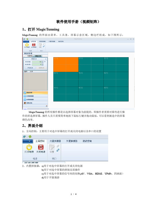
软件使用手册(视频矩阵)1、打开MagicTunningMagicTunning的界面由菜单,工具条,屏幕示意区域,侧边栏组成,如下图所示:MagicTunning的所有操作都是以选择屏幕对象为前提的,即操作者需要对那些进行操作的屏选择屏幕,操作人员只需要简单地按下鼠标左键并拖动鼠标,可以看到被选中的屏幕颜色改变。
2、界面介绍1、全局控制:主要用于对选中屏幕的打开或关闭电源以及串口的设置2、内置拼接器:a)用于对选中屏幕的打开或关闭电源b)用于对选中屏幕的拼接还原操作c)用于对选中屏幕的信号间的切换(A V、VGA、HDMI、YPbPr、四画面)d)用于开窗漫游3、矩阵系统点击侧边栏的矩阵系统,出现如下画面操作方法:展开信号源、选中需要切换的屏幕,然后在侧边栏里对需要切换到该屏幕上的该路信号源右击鼠标,如图所示4、视频文字叠加在矩阵信号源编号上单击右键选中‘菜单显示控制’如图视频文字叠加内容包括:输入描述:输入描述的内容可以通过上述的方法下载,矩阵内容定义需要在矩阵描述文件里面更改;显示内容:包括输入描述,对应的输出编号,时间;菜单位置:可以自己定义或者快速定义在左上角,左下角,右上角,右下角;5、预案管理在预案管理的编号上面单击右键,弹出预案菜单:调入该预案:执行调预案指令,该命令将调入拼接器,矩阵的预案;保存当前状态为预案:保存当前屏幕状态,保存状态包括拼接器和矩阵状态;更改名称:更改预案名称。
3、软件备份MagicTunning安装完成后,默认安装在C:\Program Files\NanJing Odin Technology\MagicTunning由于每个项目的实际环境不一样(比如所用屏的多少,矩阵的型号等),所以在更新程序前,需要将项目信息备份下来,这包括下面这些文件(所有文件都在安装目录或者子目录下):Configure.mdb包含屏的显示信息,矩阵类型等;CmdDisplay.dis需要备份(包含按键显示内容);Array 需要备份(包含矩阵信息);MagicTunning安装后并不会在其它文件夹中创建任何文件,所以,可以简单将安装目录下所有文件备份就可以了。
佳能相机Magic Lantern使用教程

佳能相机Magic Lantern使用教程Magic Lantern 菜单按删除按钮显示菜单,使用箭头键导航。
要更改值,使用SET,PLAY和Q:对于大多数菜单项,你可以:* 按SET数值向前变化* 按PLAY数值向后变化* 按Q调用专项动作(见帮助文本或屏幕上的提示)复杂的菜单项目按这3个键可能是不同的动作。
请参阅您要使用特定的菜单项的文件。
拍照模式下,除实时查看,你可以使用滚轮在ML菜单中导航。
按下放大按钮来激活编辑菜单项模式,并用滚轮改变数值。
按DISP或INFO按钮以获取有关特定菜单项的帮助。
各菜单功能简介Audio:1. Audio Meters 音频测量器2. Analog Gain 声音插值模拟增益3. L-DigitalGain 左声道增益4. R-DigitalGain 右声道增益5. AGC ACG自动增益6. Input Source 声音输入源7. Mic Power 麦克风供电8. Output volume 输出音量9. Monitoring-USB USB端口监听LiveV1. Global Draw 全局信息显示2. Zebras 斑马纹曝光不足区域显示3. Focus Peak 对焦峰值4. Magic Zoom MW对焦同步放大器5. Cropmks(0/7) 剪裁比例6. Ghost Image 鬼影显示,要选定一张照片按LV键7. Live Defish8. Spotmeter 点测光9. False Color 伪色图,SET为开关,Q键选种类10. Histo/Wavefm 录像时显示直方图11. ClearScreen 清屏,半按快门时/待机时Expo:1. ISO 自定感光率2. WhiteBalance 自定色温,LV模式下按Q可以检测3. WBShift G/M 自定白平衡偏移4. WBShift B/A 自定白平衡偏移5. Shutter 自定快门速度,LV模式下按Q检测6. Aperture 自定光圈7. Light Adjust 光线调节,高光色调优先/ALO浓度8. PictureStyle 照片风格9. REC PicStyle 录像的画面风格10. Contrast 对比度,LV模式下可实时查看11. Saturation 饱和度,LV模式下可实时查看12. Sharpness 清晰度13. Flash AEcomp 照片曝光补偿Movie:1. Bit Rate(CBR) 自定视频码率2. BuffWarnLevel 缓冲区报警设置3. Time Indicator 时间指示器4. Bitrate Info 比特率信息5. Movie Logging 生成短片文件日志6. Movie Restart 录像中断时(29分29秒)重新录像7. MovieModeRemap 视频模式映射8. REC/STBY notif 录制备用通知9. Movie REC key 录制热键设置10. Force LiveView 强制保持实时显示模式11. Force HDMI-VGA 强制同步输出HDIM或VGA信号Shoot:1. HDR Bracketing HDR档次,Q关闭/SET快门数/PLAY键设置EV值。
Fusion 150 12 x 12W Moving Head 用户手册说明书
• Make sure that the available voltage is between 100~240V, 50/60Hz.
• Make sure that the power cable is never crimped or damaged. Check the equipment and the power cable periodically.
• If the equipment has been exposed to drastic temperature fluctuation (e.g. after transportation), do not connect power or switch it on immediately. The arising condensation might damage the equipment. Leave the equipment switched off until it has reached room temperature.
• Never let the power cable come into contact with other cables. Handle the power cable and all mains voltage connections with particular caution!
示教器操作手册最终版
Magic Lantern V2.3使用手册 繁体中文完整最终版
Magic Lantern v2.3穩定支援: Canon 5D Mark II, 550D, 60D, 600D, 50D and 500D進行中的支援: Canon 5D Mark III, Canon 5D (classic), Canon 1100D/T3使用手冊www.magiclantern.fmJuly 23, 2012Magic Lantern是一個對於Canon 5D Mark II 和550D/T2i數位單眼相機等所開發增強套件的開放(GPL)架構. Magic Lantern由一個小型團體開發, 並由一個非常熱心且備受尊敬的使用者社群所協助.主動開發者:Alex–主要開發者Arm.Indy–隱蔽工具與大多數接口發起人G3gg0–逆向工程權威Coutts–轉移ML至5DNanomad–轉移ML至1100D/T3SztupY– ML USB控制器與其他功能發起人過去開發者 (回來吧!夥伴):Trammell Hudson–原始發起人以及前Magic Lantern計畫領導人AJ–開發5D Mark II 中Magic Lantern的AJ版本編碼貢獻piersg, nandoide, stefano, trho, deti, tapani, phil, RoaldFre, Colin Peart,cpc, msi, robotsound, maclema, adijiwa, kyselejsyrecek, mk11174, Scrax, OnePercent,Raymond Lo, Rob Kramer, Takashi Miyake, T obias Doerffel, Paul Nolan, Martin M, 名單還在增加 :)記憶卡工具貢獻Pel, Zeno, lichtjaar網頁團隊Redkite Bart, Nanomad, Michael Zöller, Malcolm Debono, CameraRick, Fran-cis Danforth, Scrax, 1%Magic Lantern標誌設計elJoseph感謝所有提供回覆, 回報錯誤, 並藉由捐款支援Magic Lantern計畫的使用者們!此外, 感謝CHDK團隊和所有舊5D2Magic Lantern的支持者!Magic Lantern是由獨立的製片人們在閒暇時間時開發,並且將我們心愛的相機置於危險中.我們希望從現在開始, 這能節省你的時間與麻煩, 而且我們感謝你的支持.你可以幫助我們藉由透過PayPal捐獻,或是設備上的捐獻. 你也可以藉由email聯絡我(Alex) . 感謝!1簡介·音訊: 關閉音訊增益器, 分貝計, 手動音訊控制,可選擇的輸入來源 (內部輸入,內部輸入+外部輸入, 外部輸入立體聲, 平衡), 透過A/V纜線監控音訊.·曝光輔助: 斑馬紋, 偽色曝光評估, 直條圖, 波形圖, 重點測光, 向量色度顯示器.·對焦工具: 峰值對焦, 錄影時畫面焦點放大, 陷阱對焦, 拉焦, 跟焦, 疊焦.·影片輔助: 位元速率控制, 影片資訊紀錄 (類似Exif的資訊),緩衝區超載或超過4 GB限制時自動重新記錄, 高動態範圍影片, 進階FPS 控制.·即時顯示模式調整: 對比, 飽和度, 黑暗中LiveView模式的顯示器增益.·遮罩圖示: 使用者編輯的遮罩以幫助構圖.·完整控制ISO, 快門, 白平衡和其他影像設定.·包圍攝影: 進階包圍曝光, 疊焦.·藉由LCD螢幕關閉感測器和聲音觸發以遠端遙控相機, 不須額外的硬體.·延時攝影: 縮時攝影 (影像或影片), 自動改變曝光 (手動或自動),在低的FPS下錄影(可低至0.2 FPS), 不須快門動作的無聲攝影.·長時攝影(天文攝影): B快門長時間曝光 (長達8小時).·資訊顯示: 對焦與景深資訊, CMOS溫度, 快門數, 時間.·離機閃: 從-10 到+3 EV的閃燈曝光補償(取決於當時相機的情況).·省電: 關閉螢幕或閒置時間時降低液晶螢幕背光亮度.·好用的功能: 播放模式快速變焦, 常用功能快捷鍵,客製化的選單.·以及更多!重要提醒·在移除記憶卡,打開相機的記憶卡艙蓋之前,總是等待LED燈熄滅後再打開(或等待5秒鐘)!!!(550D沒有此類問題).·如果您擁有一張可啟動ML軟體的記憶卡,並經過安裝軟體設定後,使之具有BOOTDISK的標記,但記憶卡上沒有AUTOEXEC.BIN的檔案,即使開啟相機電源,軟體也不會啟動(不管是原廠軟體還是ML都不會載入,相機螢幕也不會顯示任何畫面)!若沒有移除相機電池,相機將是當機的狀態。
Magic Head 用户手册说明书
ul. Romualda Traugutta 5, 45-667 Opole, Poland Phone: +48 77 456 23 53English and German only: +48 502 771 907Web:.E-mail:******************DESKTOP – REMOTE HEAD section1. Description of REMOTE HEAD display.J The first line:head and signal connections between desktop and head. This will take a few seconds. After selecting the ON || ON in the first line of the display “REMOTE HEAD”, head and controls are ready to work.J The second line:S Speed, speed indicator for PAN and TILT shown as a percentage from 0 to 99%.J The fourth line:2. Description of the controls and switches in REMOTE HEAD section.Joystick – Joystick Calibration:Hold down both RED lock buttons at the same time until you see the “Joy Calibration“ message dis-played. Leave the joystick in it’s centre position (do not move) until message “JoyMoveAllDir“ message is displayed. Then move the joystick in circular direction continuously (making sure you pass through its extreme points – top right, bottom right, bottom left & top left). When you see the message “DONE LOCKED“ then calibration is complete.After calibration, both axles are locked (LOCK on the display). To unlock, press the LOCK button on the axis of the PAN and TILT.Calibration should be performed in the case when joystick is left in the center/static position and the head “creeps” or/and when in the fourth line J – Joystick, instead of the character ʘ appears 0, 1, 2 or higher.HOME – button of HOME position:HOME button is used to return the settings of both head axes to starting/primary position which is the The default settings of the head allows both axes to turnover 2.5 times which means that for PAN axis itis the 2.5 rotation to the right and 2.5 rotation to the left, and for the TILT axis it is 2.5 rotation up and 2.5rotation down from so-called starting/original position.Holding down the HOME button allows you to set a new starting position (set by the operator) but not the original one that exist before the power supply is turned on. Which means that after the 1.5 rotation of PAN axis to the left and setting new HOME position (SET HOME) there is possible only 1 rotation to the left and 4 rotations to the right.Start position(Primary)(– 49,9%) 2.5 r. ← HOME → 2.5 r. (+49,9%)Start position(Set by the operator)(-20%) 1 r. ← SET HOME → 1.5 + 2.5 = 4 r. (+80%) Above example applies to both axes settings – PAN (panorama – turn left and right) and TILT (roll down – up).Please before starting the work – check the possibility of rotation and, if necessary, turn off the desktop, release the head so that the cables from it and from camera were loose, and turn on the console thus setting a new start/original position.DESKTOP – FOCUS & ZOOM sectionJ The second line: FOCUS section (left side of the display)J The third line:J The fourth line:J The first line: ZOOM section (right side of the display)J The second line: ZOOM section (right side of the display)J The fourth line:Zoom; inclination indicator of the button/Joystick “WT” of ZOOM function. Range measured 5. Description of the switches and regulators from ZOOM section:Calibration external FOCUS/ZOOM controller– Press and hold red button MAX/CAL for 8s,– Follow the instructions on the display.Perform calibration for internal and external controllers.EXTERNAL SocketsEXTERNAL PAN/TILT CONTROL – is used to connect external controllers: Hand Wheels or Pan Bar. EXTERNAL FOCUS/ZOOM CONTROL – is used to connect external FOCUS/ZOOM controller.。
- 1、下载文档前请自行甄别文档内容的完整性,平台不提供额外的编辑、内容补充、找答案等附加服务。
- 2、"仅部分预览"的文档,不可在线预览部分如存在完整性等问题,可反馈申请退款(可完整预览的文档不适用该条件!)。
- 3、如文档侵犯您的权益,请联系客服反馈,我们会尽快为您处理(人工客服工作时间:9:00-18:30)。
注意 阅读说明·使用设备前要阅读并理解所有的安全和操作说明。 保留说明·用户手册应保留以备参考。 警告 电源连接·请参照产品说明连接电源,设备使用具有接地的电源,接地脚具有保 护作用,请不要随意破坏接地脚。 关断电源·要关闭电源时可以拔掉设备后方的电源线,或者关掉设备面板开关, 或者把电源插头从电源插座上拔出。 线缆保护·不要把物品放在线缆上,以免受到挤压或夹紧,也不要践踏线缆,插 拔线缆前请先关闭电源。 设备维修·所有的维修应交给专业维修人员完成。不要尝试自己维修设备,因为 打开机盖可能使你受到电击,或出现其它危险。 断电·需要进行设备移动或其他需要断电的工作时,要关断所有的电源,包括关 断外部电源插座,拔掉电源插头,以确保您的安全。 线缆·不能在电源线、信号线、通讯线等线缆上压放物品,应避免线缆被践踏或 挤压,以防止出现漏电或短路等危险。 信号线连接·从设备上插、拔信号线时,设备需要断电,以免击穿电路。带电插 拔造成的损坏不在保修范围。 散热孔·设备箱盖和箱底可能有散热用的开孔,不要堵塞这些开孔,以防热量积 聚,损坏设备。 设备固定·合理固定设备,确保设备放置合适并且稳固,防止设备跌落。 环境 ·设备工作的环境要注意防尘、防潮。 提示 :此设备产生、使用并能够发出无线电波,如果不按照操作手册安装和使用, 注意 注意: 可能会干扰无线电通讯。 注意:此设备已经在外围设备上通过屏蔽电缆进行测试。此设备必须采用屏蔽电 缆以保证其使用。
第 3页
DC806 系统说明书 二、 产品说明
欢迎选用我公司第三代液晶拼接器处理器, 感谢您对我公司产品的支持! 为了您能更好 的使用本产品,使用前请仔细阅读本手册。 帝彩DC-806液晶图像拼接系统是我公司为大屏幕拼接专业设计的拼接系统,该系统 主要由三部分组成: � 帝彩DC-806型液晶图像拼接处理器 � 三星专业DID拼接屏 � 帝彩DC-806型液晶拼接系统专用软件MagicTunning 帝彩 DC-806 型液晶图像拼接处理器是我公司大屏幕拼接产品家族中的一员,采用 独特的嵌入式结构设计,可接受各种图像信号源输入,直接驱动全系列的大尺寸液晶屏(26 寸以上),并经分割、放大后,实时无失真地在各种大屏幕图像拼接墙体上显示。处理过程完 全硬件化, 不需要电脑和启动软件等操作,非常简便。 画面无延时,无拖尾现象, 自然流畅, 画质细腻,最大支持 15X15 的液晶屏拼接。 帝彩 DC-806 型液晶图像拼接处理器采用了运动侦测与补偿运算、内插运算、边缘 平滑处理及杂波信号抑制等尖端处理技术,其 3D 视频亮色分离电路单元, 3D 的逐行处理 及帧频归一转化电路单元, 3D 数字信号降噪单元,可将普通 PAL/NTSC 隔行扫描视频信 号采集变为逐行扫描的,高画质、高分辨率的高清电视和计算机图像信号。 帝彩 DC-806 型液晶图像拼接处理器支持计算机图像信号输入及其显示,可实现最 高达 1920x1080 高分辨率 WUXGA 输出,支持全系列的大尺寸液晶屏。 帝彩系列处理器可以支持多路不同的视频源, 同时显示在不同的屏幕上, 使用者也可选 择一路视频源或 RGB 信号放大至原始图像的 N×M 倍, 在由显示单元组成的墙体上实现大 屏幕拼接显示。 三星 DID 液晶屏是专为拼接市场而定做的,DID 屏具有高亮度,高对比度,高色域, 高分辨率,边框窄等优点 MagicTunning 是南京欧帝为 DC-806 拼接系统专业开发的控制软件, 涵盖了拼接 领域的所有功能,包括拼接控制,矩阵联动,系统控制,参数调整等。MagicTunning 具 有功能强大, 操作人性化等优点, 其在业内独创开发了参数拖动调整, 屏参复制, 一键还原, 单击放大,还原,矩阵场景,轮切等功能。并且,MagicTunning 还内置来公安,酒吧, 水利等行业的特殊功能。 由于液晶画面调整需要专业的知识,MagicTunning 也支持两种运行模式,管理员模 式和操作员模式, 管理员模式下可以对系统进行全面控制, 而操作员只能进行常见的操作控 制,从而避免了系统实际运行过程06 系统说明书
版本历史
2010-10-20 V1.00 MagicTunning 版本:V4.5 DC806 版本:V2.0 2011-05-29 V1.10 MagicTunning 版本:V5.0 DC806 版本:V2.8 保留版本更新的权利;
第 2页
DC806 系统说明书 一、 安全说明
5.
程序的更新备份.......................................................................................................... 31
DC806 系统说明书
感谢您使用本产品!
—— 为了您和设备的安全, 请您务必在使用前阅读
选择屏幕............................................................................................................................ 19 简单的操作........................................................................................................................ 20 操作模式............................................................................................................................ 20 显示设置............................................................................................................................ 20 系统设置............................................................................................................................ 22 画面设置............................................................................................................................ 23 屏幕设置............................................................................................................................ 24 场景文件............................................................................................................................ 26 矩阵设置文件.................................................................................................................... 27 预案管理............................................................................................................................ 27 矩阵操作............................................................................................................................ 28 视频文字叠加.................................................................................................................... 28
帝彩 DC-806 液晶图像拼接系统
系统说明书
目 录
一、 安全说明.......................................................................................................................... 3 注意....................................................................................................................................... 3 警告....................................................................................................................................... 3 提示....................................................................................................................................... 3 二、 产品说明......................................................................................................................... 4 三、 DC806 的分类............................................................................................................. 5 四、 接口说明......................................................................................................................... 6 五、 系统连接安装方式......................................................................................................... 8 六、 故障检修及使用注意事项.......................................................................................... 10 七、 性能指标...................................................................................................................... 11 八、 控制协议...................................................................................................................... 12 九、 指令说明...................................................................................................................... 13 十、 控制软件 MagicTunning....................................................................................... 15 1. 2. 3. 4. 系统运行环境.............................................................................................................. 15 安装系统...................................................................................................................... 16 界面介绍...................................................................................................................... 19 使用 MagicTunning............................................................................................... 19