柯尼卡美能达bizhubC364C284C224彩色数码复合机资料
柯尼卡美能达 bizhub C252打印机 说明书

柯尼卡美能达的全新品牌—bizhub,为您通往成功开启新的门户。
为您的工作带来高度自由
无论何时何地自由获取所需信息,最大限度地 提高效率。无论是在家中,在外出途中,或者 在客户那里,只要连上bizhub,您的工作就会 变得更快、更灵巧。
使您置身信息应用的最前沿
汇集、管理、交流,通过bizhub创新的技术, 可以有效地运用信息,并提高其价值。同时, 能不断地获取各类资讯,从而在此过程中创建 高价值的数据资料库。bizhub给予您将信息转 化为资产的能力。
拥有柯尼卡美能达彩色MFP bizhub C252,即可在一台小巧紧凑的机器上完成文档存储,共享,分发, 管理,转换和输出。它可提供多种功能,为您创建色彩逼真或黑白分明的生动商业文档,同时简化工作 流程,提高工作效率。它是中小型办公场所一体化办公和大型办公场所分散办公的理想选择,是黑白打 印机的完美换代设备。小巧紧凑的bizhub C252将改变您的办公方式。
SMTP, TCP/IP, HTTP, FTP, LDAP
Windows 98SE/Me, Windows NT4.0 SP6,
Windows 2000, Windows XP, Windows Server 2003
TIFF, PDF, Compact PDF, JPEG TWAIN驱动程序(实时模式推扫描/拉扫描), HDD TWAIN驱动程序
* 作为“能源之星”的伙伴,柯尼卡美能达商用科技株式会社抱
着节省能源的宗旨而生产这部符合“能源之星”标准的产品。
* 能源之星是美国的注册商标。
柯尼卡美能达数码复合机采用环保设计。
■ 符合能源之星标准 ■ 使用可回收材料 ■ ISO认证工厂生产
工作台DK-502
安全使用的要求
HP PageWide Pro MFP 577dw系列用户指南说明书

用户指南版权与许可©2016 版权所有HP Development Company, L.P.保留所有权利。
除非版权法允许,否则在未经HP 预先书面许可的情况下,严禁转载、改编或翻译本手册的内容。
本文档包含的信息如有更改,恕不另行通知。
HP 产品与服务的全部保修条款在此类产品和服务附带的保修声明中均已列明。
此处内容不代表任何额外保修。
HP 对此处任何技术性或编辑性的错误或遗漏概不负责。
Edition 2016 年2 月1 日商标声明Adobe®、Acrobat®和PostScript®是 Adobe Systems Incorporated 的商标。
Intel® Core™ 是Intel Corporation 在美国和其它国家/地区的商标。
Java™ 是Sun Microsystems, Inc. 在美国的商标。
Microsoft®、Windows®、Windows® XP 和Windows Vista® 是Microsoft Corporation 在美国的注册商标。
UNIX®是The Open Group 的注册商标。
能源之星和能源之星标记是美国环保署拥有的注册商标。
目录1产品基本信息 (1)产品功能 (2)环境功能 (2)辅助功能 (3)产品视图 (4)左前视图 (4)右前视图 (5)后视图 (5)墨盒门视图 (6)开机/关机 (7)打开产品电源 (7)管理电源 (7)关闭产品电源 (8)使用控制面板 (9)控制面板按钮 (9)控制面板主屏幕 (10)控制面板仪表板 (10)控制面板的应用程序文件夹 (11)控制面板快捷方式 (11)帮助功能 (12)打印机信息 (12)帮助动画 (13)安静模式 (14)从控制面板打开或关闭安静模式 (14)从EWS 打开或关闭安静模式 (14)2连接产品 (15)将产品接入计算机或网络 (16)使用USB 电缆连接产品 (16)将产品连接到网络 (16)支持的网络协议 (16)ZHCN iii使用有线网络连接产品 (17)使用无线网络(仅限无线型号)连接产品 (17)使用WiFi 设置向导将产品连接到无线网络 (18)使用WPS 将产品连接至无线网络 (18)手动将产品连接至无线网络 (19)使用Wi-Fi Direct 将计算机或设备连接至产品 (20)打开Wi-Fi Direct (20)从具有无线功能的移动设备打印 (20)从具有无线功能的计算机进行打印(Windows) (20)从具有无线功能的计算机进行打印(OS X) (20)为已接入网络的无线产品安装HP 打印机软件 (23)打开打印机软件(Windows) (24)管理网络设置 (25)查看或更改网络设置 (25)设置或更改产品密码 (25)在控制面板中手动配置TCP/IP 参数 (25)链路速度和双工设置 (26)3打印机管理和服务 (27)HP 嵌入式Web 服务器(EWS) (28)关于EWS (28)关于cookie (28)启动EWS (29)功能 (29)主页选项卡 (29)“扫描”选项卡 (30)“传真”选项卡 (31)“Web 服务”选项卡 (31)“网络”选项卡 (31)“工具”选项卡 (31)“设置”选项卡 (32)Web 服务 (33)何为Web 服务? (33)HP ePrint (33)打印应用程序 (33)设置Web 服务 (33)使用Web 服务 (34)HP ePrint (34)打印应用程序 (35)删除Web 服务 (35)iv ZHCNHP Web Jetadmin 软件 (37)产品安全功能 (38)安全声明 (38)防火墙 (38)安全性设置 (39)固件更新 (39)打印机软件(Windows) 中的HP Printer Assistant (40)打开HP Printer Assistant (40)功能 (40)Connected 选项卡。
赛米控CAT3647 3通道超高效率LED驱动器 32级调光说明书

CAT36473-Channel Ultra High Efficiency LED Driver with 32 Dimming LevelsDescriptionThe CAT3647 is a high efficiencye fractional charge pump that can drive up to three LEDs programmable by a one wire digital interface. The inclusion of a 1.33x fractional charge pump mode increases device efficiency by up to 10% over traditional 1.5x charge pumps with no added external capacitors.Low noise input ripple is achieved by operating at a constant switching frequency which allows the use of small external ceramic capacitors. The multi−fractional charge pump supports a wide range of input voltages from 2.4 V to 5.5 V.The EN/DIM logic input functions as a chip enable and a digital dimming interface for setting the current in all the LED channels. The 1−wire pulse−dimming interface supports 32 linear steps from full−scale down to zero current.The device is available in the tiny 16−pad TQFN 3mm x 3mm package with a max height of 0.8mm.ON Semiconductor’s 1.33x, charge pump switching architecture is patented.Features•High Efficiency 1.33x Charge Pump•Charge Pump: 1x, 1.33x, 1.5x, 2x•Drives up to 3 LEDs at 30 mA Each•1−wire EZDim 32 Linear Steps•Power Efficiency up to 92%•Low Noise Input Ripple in All Modes•“Zero” Current Shutdown Mode•Soft Start and Current Limiting•Short Circuit Protection•Thermal Shutdown Protection•16−pad TQFN Package•These Devices are Pb−Free, Halogen Free/BFR Free and are RoHS CompliantApplications•LCD Display Backlight•Cellular Phones•Digital Still Cameras•Handheld DevicesTQFN−16HV3 SUFFIXCASE 510ADPIN CONNECTIONSMARKING DIAGRAMDevice Package Shipping†ORDERING INFORMATIONCAT3647HV3−GT2(Note 1)TQFN−16(Pb−Free)2,000/Tape & Reel 1.NiPdAu Plated Finish (RoHS−compliant).LED1GNDNCNCC2−C2+C1−C1+LED2LED3NCRSETEN/DIMVOUTNCVIN1(Top View)JAAPAXXXYWWJAAP = CAT3647HV3−GT2A = Assembly LocationXXX = Last Three Digits of Assembly Lot Number Y = Production Year (Last Digit)WW = Production Week (Two Digits)†For information on tape and reel specifications, including part orientation and tape sizes, please refer to our T ape and Reel Packaging Specifications Brochure, BRD8011/D.Figure 1. Typical Application Circuitm FOUT Table 1. ABSOLUTE MAXIMUM RATINGSParameterRating Unit VIN, LEDx, C1±, C2±, EN/DIM, RSET voltage 6V VOUT voltage7V Storage Temperature Range −65 to +160°C Junction Temperature Range−40 to +150°CStresses exceeding those listed in the Maximum Ratings table may damage the device. If any of these limits are exceeded, device functionality should not be assumed, damage may occur and reliability may be affected.Table 2. RECOMMENDED OPERATING CONDITIONSParameterRating Unit VIN2.5 to 5.5V Ambient Temperature Range −40 to +85°C I LED per LED pinup to 30mA LED Forward Voltage Range1.3 to 4.3VFunctional operation above the stresses listed in the Recommended Operating Ranges is not implied. Extended exposure to stresses beyond the Recommended Operating Ranges limits may affect device reliability.NOTE:Typical application circuit with external components is shown above.Table 3. ELECTRICAL OPERATING CHARACTERISTICS(over recommended operating conditions unless specified otherwise) V IN = 3.6 V, EN = High, T AMB = 25°CSymbol Name Conditions Min Typ Max UnitsI Q Quiescent Current1x mode, excluding load1.33x mode, excluding load1.5x mode, excluding load2x mode, excluding load 1.01.72.22.4mAI QSHDN Shutdown Current V EN = 0 V1m A I LED-ACC LED Current Setting RSET = 3.74 k W20mARSET = 7.50 k W10I LED-ACC LED Current Accuracy(I LEDAVG – I NOMINAL) / I NOMINALRSET = 4.99 k W±2% I LED-DEV LED Channel Matching(I LED - I LEDAVG) / I LEDAVG±1.5% V RSET RSET Regulated Voltage0.580.60.62VR OUT Output Resistance (open loop)1x mode1.33x mode, V IN = 3 V1.5x mode, V IN =2.7 V2x mode, V IN = 2.4 V 0.85510WF OSC Charge Pump Frequency 1.33x and 2x mode1.5x mode 0.8111.31.31.6MHzI SC_MAX Output short circuit Current Limit V OUT < 0.5 V50mA I IN_MAX Input Current Limit V OUT > 1 V, 1x mode250mA LED TH1x to 1.33x or 1.33x to 1.5x or 1.5x to 2xTransition Thresholds at any LED pin130mV V HYS1x Mode Transition Hysteresis400mV T DF Mode Transition Filter Delay120m sR EN/DIM V HI V LO EN/DIM Pin− Internal Pull-down Resistor− Logic High Level− Logic Low Level1.31000.4k WVVT SD Thermal Shutdown150°C T HYS Thermal Hysteresis20°C V UVLO Undervoltage lockout (UVLO) threshold 1.6 1.8 2.0V Product parametric performance is indicated in the Electrical Characteristics for the listed test conditions, unless otherwise noted. Product performance may not be indicated by the Electrical Characteristics if operated under different conditions.Table 4. RECOMMENDED EN/DIM TIMING(For 2.4 V ≤ V IN ≤ 5.5 V, over full ambient temperature range -40°C to +85°C.)Symbol NameConditionsMin TypMax Units T LO EN/DIM program low time 0.2100m s T HI EN/DIM program high time0.2m s T PWRDWN EN/DIM low time to shutdown 1.5ms T LEDLED current settling time40m sFigure 2. EN/DIM Digital Dimming Timing DiagramLED LED Current SettingThe full scale LED current is set by the external resistor connected between the RSET pin and ground. Table 5 lists standard resistor values for several LED current settings.Table 5. RESISTOR RSET AND LED CURRENTFull Scale LED Current [mA]RSET [k W ]237.4514.7107.5015 4.9920 3.7425 3.00302.49Figure 3. Efficiency vs. Input VoltageFigure 4. Efficiency vs. Li −Ion VoltageINPUT VOLTAGE (V)INPUT VOLTAGE (V)405060708090100405060708090100Figure 5. Quiescent Current vs. Input VoltageFigure 6. Quiescent Current vs. TemperatureINPUT VOLTAGE (V)TEMPERATURE (°C)0123412080400−4001234Figure 7. LED Current Change vs. InputVoltage Figure 8. LED Current Change vs.TemperatureINPUT VOLTAGE (V)TEMPERATURE (°C)−10−8−4−202610−10−8−4−204610E F F I C I E N C Y (%)E F F I C I E N C Y (%)Q U I E S C E N T C U R R E N T (m A )Q U I E S C E N T C U R R E N T (m A )L E D C U R R E N T V A R I A T I O N (%)L E D C U R R E N T V A R I A T I O N (%)2x 1.5x1.33x 1x−648−628Figure 9. Switching Frequency vs.TemperatureFigure 10. Output Resistance vs. Input VoltageTEMPERATURE (°C)INPUT VOLTAGE (V)0.70.80.91.01.11.21.3 5.04.55.54.03.53.02.52.024681012Figure 11. Power Up in 1x Mode Figure 12. Power Up in 1.33x ModeFigure 13. Power Up in 1.5x Mode Figure 14. Power Up in 2x ModeS W I T C H I N G F R E Q U E N C Y (M H z )O U T P U T R E S I S T A N C E (W )1x1.33x1.5x2xFigure 15. Power Up Delay (1x Mode)Figure 16. Power Down Delay (1x Mode)Figure 17. Operating Waveforms in 1x ModeFigure 18. Switching Waveforms in1.33x ModeFigure 19. Switching Waveforms in1.5x Mode Figure 20. Switching Waveforms in2x ModeFigure 21. Foldback Current Limit Figure 22. LED Current vs. LED Pin VoltageOUTPUT CURRENT (mA)LED PIN VOLTAGE (mV)00.51.01.52.03.03.54.030025020015010050010203040Figure 23. Dimming WaveformO U T P U T V O L T A G E (V )L E D C U R R E N T (m A )2.5Table 6. PIN DESCRIPTIONName FunctionLED1LED1 cathode terminal.LED2LED2 cathode terminal.LED3LED3 cathode terminal.RSET Connect resistor RSET to set the LED current.EN/DIM Device enable (active high) and Dimming Control.VOUT Charge pump output connected to the LED anodes.VIN Charge pump input, connect to battery or supply.C1+Bucket capacitor 1 Positive terminalC1-Bucket capacitor 1 Negative terminalC2+Bucket capacitor 2 Positive terminalC2-Bucket capacitor 2 Negative terminalGND Ground ReferenceNC Not connected inside package.GND Connect to GND on the PCB.Pin FunctionVIN is the supply pin for the charge pump. A small 1m F ceramic bypass capacitor is required between the VIN pin and ground near the device. The operating input voltage range is from 2.5V to 5.5V. Whenever the input supply falls below the under-voltage threshold (1.8V), all the LED channels are disabled and the device enters shutdown mode. EN/DIM is the enable and one wire dimming input for all LED channels. Levels of logic high and logic low are set at 1.3V and 0.4V respectively. When EN/DIM is initially taken high, the device becomes enabled and all LED currents are set to the full scale according to the resistor R SET. To place the device into “zero current” shutdown mode, the EN/DIM pin must be held low for at least 1.5ms. VOUT is the charge pump output that is connected to the LED anodes. A small 1 m F ceramic bypass capacitor is required between the VOUT pin and ground near the device. GND is the ground reference for the charge pump. The pin must be connected to the ground plane on the PCB.C1+, C1- are connected to each side of the ceramic bucket capacitor C1.C2+, C2- are connected to each side of the ceramic bucket capacitor C2.LED1, LED2, LED3 provide the internal regulated current sources for each of the LED cathodes. These pins enter high-impedance zero current state whenever the device is placed in shutdown mode.TAB is the exposed pad underneath the package. For best thermal performance, the tab should be soldered to the PCB and connected to the ground plane.RSET is connected to the resistor (R SET) to set the full scale current for the LEDs. The voltage at this pin regulated to 0.6V. The ground side of the external resistor should be star connected back to the GND of the PCB. In shutdown mode, RSET becomes high impedance.Block DiagramFigure 24. CAT3647 Functional Block DiagramBasic OperationAt power-up, the CAT3647 starts operating in 1x mode where the output will be approximately equal to the input supply voltage (less any internal voltage losses). If the output voltage is sufficient to regulate all LED currents, the device remains in 1x operating mode.If the input voltage is insufficient or falls to a level where the regulated currents cannot be maintained, the device automatically switches into 1.33x mode (after a fixed delay time of about 120 m s). In 1.33x mode, the output voltage is approximately equal to 1.33 times the input supply voltage (less any internal voltage losses).This sequence repeats in the 1.33x and 1.5x mode until the driver enters the 2x mode. In 1.5x mode, the output voltage is approximately equal to 1.5 times the input supply voltage. While in 2x mode, the output is approximately equal to 2 times the input supply voltage.If the device detects a sufficient input voltage is present to drive all LED currents in 1x mode, it will change automatically back to 1x mode. This only applies for changing back to the 1x mode. The difference between the input voltage when exiting 1x mode and returning to 1x mode is called the 1x mode transition hysteresis (V HYS) and is about 400 mV.LED Current SelectionAfter power-up, the LED current is set by the external resistor (R SET ) value and the number of pulses (n) on the EN/DIM input as follows:LED current +125 0.6VR SETǒ31*n31ǓThe full scale current is calculated from the above formulawith n equal to zero.The EN/DIM pin has two primary functions. One function enables and disables the device. The other function is LED current dimming with 32 different levels by pulsing the input signal, as shown on Figure 25. On each consecutive pulse rising edge, the LED current is decreased by about 3.2%(1/31th of the full scale value). After 30 pulses, the LED current is 3.2% of the full scale current. On the 31st pulse, the current drops to zero, and then goes back to full scale on the following pulse.Each pulse width should be between 200ns and 100m s.Pulses faster than the minimum T LO may be ignored and filtered by the device. Pulses longer than the maximum T LO may shutdown the device. By pulsing the EN/DIM signal at high frequency, the LED current can quickly be set to zero.The LED driver enters a “zero current” shutdown mode if EN/DIM is held low for 1.5ms or more.The dimming level is set by the number of pulses on the EN/DIM after the power-up, as shown in Table 7.Table 7. DIMMING LEVELSFull Scale Current in %Dimming Pulses [n]1000971942903874845816777748719681065116112581355145215481645174218391935203221292226232324192516261327102862933003110032Figure 25. EN/DIM Digital Dimming Timing DiagramLEDUnused LED ChannelsFor applications not requiring all the channels, it is recommended the unused LED pins be tied directly to VOUT (see Figure 26).Figure 26. Application with 2 LEDsProtection ModeIf an LED is disconnected, the driver senses that and automatically ignores that channel. When all LEDs are disconnected, the driver goes to 1x mode where the output is equal to the input voltage.As soon as the output exceeds about 6V , the driver resets itself and re-evaluates the mode.If the die temperature exceeds +150°C, the driver will enter a thermal protection shutdown mode. When the device temperature drops by about 20°C, the device will resume normal operation.LED SelectionLEDs with forward voltages (V F ) ranging from 1.3V to 4.3V may be used. Selecting LEDs with lower V F is recommended in order to improve the efficiency by keeping the driver in 1x mode longer as the battery voltage decreases.For example, if a white LED with a V F of 3.3 V is selected over one with V F of 3.5 V , the driver will stay in 1x mode for lower supply voltage of 0.2 V . This helps improve the efficiency and extends battery life.External ComponentsThe driver requires four external 1 m F ceramic capacitors for decoupling input, output, and for the charge pump. Both capacitors type X5R and X7R are recommended for the LED driver application. In all charge pump modes, the input current ripple is kept very low by design and an input bypass capacitor of 1 m F is sufficient.In 1x mode, the device operates in linear mode and does not introduce switching noise back onto the supply.Recommended LayoutIn charge pump mode, the driver switches internally at a high frequency. It is recommended to minimize trace length to all four capacitors. A ground plane should cover the area under the driver IC as well as the bypass capacitors. Short connection to ground on capacitors C IN and C OUT can be implemented with the use of multiple via. A copper area matching the TQFN exposed pad (TAB) must be connected to the ground plane underneath. The use of multiple via improves the package heat dissipation.Figure 27. TQFN-16 Recommended LayoutTQFN16, 3x3CASE 510AD −01ISSUE ADATE 19 MAR 2008SIDE VIEWTOP VIEWBOTTOM VIEWFRONT VIEWNotes:(1) All dimensions are in millimeters.(2) Complies with JEDEC MO-220.SYMBOLMIN NOM MAX A 0.700.750.80A10.000.020.05A30.20 REF b 0.180.250.30D 2.90 3.00 3.10D2 1.40−−− 1.80E 3.00E2 1.40−−− 1.80e 2.900.50 BSC 3.10L0.300.400.50MECHANICAL CASE OUTLINEPACKAGE DIMENSIONSON Semiconductor and are trademarks of Semiconductor Components Industries, LLC dba ON Semiconductor or its subsidiaries in the United States and/or other countries.ON Semiconductor reserves the right to make changes without further notice to any products herein. ON Semiconductor makes no warranty, representation or guarantee regarding the suitability of its products for any particular purpose, nor does ON Semiconductor assume any liability arising out of the application or use of any product or circuit, and specifically disclaims any and all liability, including without limitation special, consequential or incidental damages. ON Semiconductor does not convey any license under its patent rights nor thePUBLICATION ORDERING INFORMATIONTECHNICAL SUPPORTNorth American Technical Support:Voice Mail: 1 800−282−9855 Toll Free USA/Canada Phone: 011 421 33 790 2910LITERATURE FULFILLMENT :Email Requests to:*******************onsemi Website: Europe, Middle East and Africa Technical Support:Phone: 00421 33 790 2910For additional information, please contact your local Sales Representative。
konica minolta magicolor 7450 ii 彩色激光打印机使用手册说明书
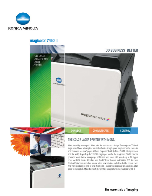
THE COLOR LASER PRINTER WITH MORE.More versatility. More speed. More color for business and design. The magicolor ®7450 II large-format laser printer gives you brilliant color at high speed for your creative concepts and ‘business as usual’ pages. With an Emperon ®Print System, 733 MHz G4 processor and the ability to print up to 120,000 pages per month, the magicolor 7450 II has the power to serve diverse workgroups of PC and Mac users with speeds up to 24.5 ppm color and B&W. Konica Minolta’s own Simitri ®toner formula and 9600 x 600 dpi-class PhotoART Contone resolution ensure prints look fabulous, with true-to-life, vibrant color.And there’s virtually no limit to what it can print—supporting pages up to banner size, plain CONNECT_COMMUNICATE_CONTROL_magicolor 7450 II_FULL COLOR _LARGE FORMAT _LASER _PRINTERSPEED PLUS ALL THE EXTRASFast—from ‘click’ to print.An Emperon Print System, powerful 733 MHz G4processor and custom acceleration hardware manage print jobs efficiently—even from multiple users—to deliver its first B&W page in just 8.2 seconds,first color page in 11.4 seconds, and subsequent prints at 24.5 ppm. Work team equipped. The magicolor 7450 II has PostScript 3 (v. 3016), PCL 6, PDF and JPEG/TIFF Direct Print emulations**, and includes TCP/IP ,IPX/SPX, EtherTalk ®and UDP protocols for seamless document printing and the latest in network security. With its Emperon 5.1 controller technology, the magicolor 7450 II serves diverse teams of Windows, Macintosh ®and Linux ®users.CREATIVE FLEXIBILITYBroad media sizes and types.Standard letter-sized documents.Spreadsheets on legal paper. F ull-bleed tabloid designs with crop and registration marks. Banner posters. Postcards and envelopes. Custom creations. The printer includes a 250-sheet multipurpose cassette and 100-sheet manual feed tray that accepts thick stock up to 140 lb. Index. Add up to three 500-sheet cassettes for higher print traffic and to bring paper capacity to its maximum of 1,850 sheets.DO BUSINESS_BETTERPRECISION COLORColor you expect.The magicolor 7450 II features automatic and hands-on technologies—including a built-in ICC-based matching system—that allow you to get the results that match your expectations. The printer automatically maintains color consistency page after page with enhanced Automatic Image Density Control (eAIDC) smart calibration system.Professional print quality. The magicolor 7450 II’s 9600 x 600 dpi-class resolution generates true-to-life photographic detail, smooth color gradients,and highly saturated deep blacks using contone printing technology. The printer uses Simitri Polymerized Toner for exceptional results and durable prints that don’t smear or fade.*Based on letter/A4 page size **HDD is requiredFEATURES, OPTIONS & BENEFITSIntuitive and easy.F ront-door access to color-coded supplies makes replacement quick and simple. The printer’s 4-line LCD display communicates toner levels and printer status clearly, and navigates you through the menu system step by step.New creative tools.PDF 1.6* makes it possible to print transparent objects embedded in documents for true-to-life proofs. Image CMYK Gray feature prints non-text black objects using black toner rather than processed black (CMYK) for richer results. Select Thin Line Mode to print thin lines and small text for important details.Prints—large and small.Supporting a wide range of media sizes, the magicolor 7450 II can print on custom media as small as 3.55" x 5.50", to 12.25" x 18" for full-bleed tabloid designs, and up to banner size of 12.25" x 47.24". Select N-up, booklet printing or poster printing in the driver, and customize output. Equip the printer with a duplexer for automatic two-sided printing of reports, hand-outs and more.Optional hard drive.Add a 40 GB HDD to store fonts and forms, direct print files and access secure print features.Color choice.Simulate color you see on your monitor,printing press or other device via the user-friendly print driver. The magicolor 7450 II also includes SWOP ,Commercial Press, Eurocolor, TOYO, DIC, and SNAP press emulations and PANTONE ®Color tables for complete color control.Up to 120,000 prints per month.The magicolor 7450 II can handle the load when print traffic is heavy with its maximum monthly duty cycle of 120,000 prints. Backed by a one-year on-site warranty, it’s certified reliable.Photos on the fly.Connect your PictBridge-compatible digital camera to the magicolor 7450 II and print photos in brilliant color. Choose index prints, multiple copies and N-up prints.Internet printer management. Use your web browser and PageScope Web Connection, an embedded web server, to manage, configure and troubleshoot the printer from anywhere on the network.Convenient PageScope Management.An entire software suite, PageScope lets users and administrators monitor and manage print jobs and devices—from theconvenience of their workstation.BUILD TO SERVE. CUSTOMIZE THEMAGICOLOR 7450 II TO SUIT THE WAY YOU DO BUSINESS. ITS MULTIPLE DOCUMENT HANDLING OPTIONS ADD FLEXIBILITY AND PRODUCTIVITY TO KEEP PEOPLE AND PAPER MOVING.24PPM24PPMSUPERB COLOR QUALITY .SIMITRI POLYMERIZED TONER GIVES PRINTS EXCEPTIONAL COLOR—RICHER GRAPHICS, SHARPER TEXT AND LINES, SMOOTHER GRADATIONS, SUPERIOR IMAGES AND HALFTONEREPRODUCTIONS.23456718*HDD is requiredItem #: MC7450IIBRO12/08Office imagery courtesy of Knoll, Inc.© 2008 KONICA MINOLTA BUSINESS SOLUTIONS U.S.A., INC.All rights reserved. Reproduction inwhole or in part without written permission is prohibited. Konica Minolta is a trademark of KONICA MINOLTA HOLDINGS, INC. The essentials of imaging is a registered trademark of KONICA MINOLTA HOLDINGS, INC. Emperon, magicolor and PageScope are registered trademarks of KONICA MINOLTA BUSINESS TECHNOLOGIES,INC. Simitri is a registered trademark of KONICA MINOLTA BUSINESS SOLUTIONS U.S.A., INC. All other brands and product names are registered trademarks or trademarks of their respective owners.Design and specifications are subject to change without notice.KONICA MINOLTABUSINESS SOLUTIONS U.S.A., INC.100 Williams Drive Ramsey, NJ 07446/solutionsPRINTING PROCESS PRINT METHOD:Single-pass, large-format color laser PRINT SPEED*:24.5 ppm color, 24.5 ppm b&w*Exact print speed differs depending on system configuration, software application, driver and document complexity.WARM-UP TIME:99 seconds or less FIRST-PAGE OUTPUT TIME:Color: 11.4 secondsMonochrome: 8.2 seconds RESOLUTION:9600 x 600 dpi-class with PhotoART RECOMMENDED MONTHLY DUTY CYCLE:120,000 printsHARDWARE AND SOFTWARE CAPABILITIES PROCESSOR:733 MHz G4 PowerPC 7447A MEMORY:256 MB DDR SDRAM Upgradeable to 1,024 MB HARD DISK DRIVE (optional)*: 40 GB*For downloaded fonts, forms and color profiles;electronic collation; job accounting; direct PDF, JPEG and TIFF printing; proof then print, secured job, print and hold, and stored job functions.OPERATING SYSTEM COMPATIBILITY:Windows Vista Windows Vista x64Windows Server 2003Windows Server 2003 x64Windows XP Windows XP x64Windows 2000Macintosh OS 9 (v9.1+)Macintosh OS X (v10.2+)Macintosh OS X (v10.5+)Linux Red Hat 9Linux SuSE 8.2PRINTER EMULATIONS:PostScript 3 (v. 3016)PCL 6PCL XL (3.0)PDF 1.6*JPEG/TIFF Direct Print**Requires optional Hard DriveCAMERA DIRECT PHOTO PRINTING:PictBridge 1.0 via USB 1.1 Host Port PRINTER MANAGEMENT:PageScope Net CarePageScope Web Connection PageScope Network Setup PageScope EMS Plug-ins Tivoli NetView (2.0)CA Unicenter 2.0HP OpenViewMicrosoft Management Console (MMC)PageScope Plug and Print PageScope NDPS Gateway PageScope Direct Print Status Monitor Download ManagerCOLOR SUPPORT:Enhanced Automatic Image Density Control (eAIDC)ICC device profilesAutomatic ICC-based color matchingSWOP , Commercial Press, EuroColor , DIC,SNAP and TOYO press emulations PANTONE Color TablesINTERFACE SUPPORTGigabit Ethernet (10/100/1000BaseTX)IEEE 1284 Parallel (supports Microsoft‘Plug and Play’)USB 2.0 (supports Microsoft ‘Plug and Play’)USB 1.1 Host Port**For Camera Direct Photo PrintingPROTOCOLS:TCP/IP EtherTalkIPX/SPX (NetWare 4/5/6), NDS Bindery, NDPS ARP , Ping/ARPDHCP , AutoIP , BOOTP FTPHTTP , HTTPS IPP1.1LPD NetBEUI SLP SMB SMTP SNMPTCP/IP socket Telnet UDP UPnPPAPER HANDLINGSTANDARD PAPER INPUT:250-sheet multipurpose cassette 100-sheet manual feed tray OPTIONAL PAPER INPUT:500-sheet cassette (add up to 3)Banner traySTANDARD PAPER OUTPUT:350-sheet face-down output tray OPTIONAL AUTOMATIC DUPLEXER:For two-sided printing (plain paper only)PAPER SIZES SUPPORTED*:250-sheet multipurpose cassette (standard):Letter Legal Ledger 4" x 6"12" x 18"Executive FolioGovt. Letter Govt. Legal UK Quarto SP Folio Statement A3, A4, A5, A6B4, B5, B6Custom sizes:(W) 3.55"-12.25" to (L) 5.5"-18"(W) 90-311 mm to (L) 140-457 mmEnvelopes: Monarch, Com10, DL, B5 (ISO), C5Postcards: Double100-sheet manual feed tray (standard):Same as multipurpose cassette plus custom sizes:(W) 3.55"-12.25" to (L) 5.5"-47.24"(W) 90-311 mm to (L) 140-1200 mm500-sheet cassette (optional):Letter Legal Ledger Executive Govt. Letter Govt. Legal Statement A3, A4, A5B4, B5Duplexer (optional):Letter Legal Ledger 12" x 18"Executive FolioGovt. Letter Govt. Legal UK Quarto SP Folio Statement A3, A4, A5B4, B5Custom sizes:(W) 3.55"-12.25" to (L) 5.5"-18"(W) 90-311 mm to (L) 140-457 mm*See Konica Minolta Media Guide for more informationPRINTABLE AREA:0.16" (4 mm) from left & right edges 0.17" (4.2 mm) from top & bottom edges 0.08" (2 mm) from all edges for sizes 12.25" x 18" and above PAPER WEIGHTS:Plain paper: 16-24 lb. Bond (60-90 g/m )Thick Stock: Up to 140 lb. Index (256 g/m )PRINT MEDIA:Plain Paper Letterhead Thick Stock Glossy Stock Transparencies Laser Quality Labels Envelopes PostcardsBanner - up to 12.25" x 47.24"(311 x 1200 mm)PHYSICAL TYPE:Laser printer with Emperon Print System DIMENSIONS (WXDXH):25.5" x 23.6" x 18.7"(648 x 606 x 477 mm)WEIGHT:133.4 lbs. (60.5 kg) - w/consumables 114.6 lbs. (52 kg) - w/o consumables 176.4 lbs. (80 kg) - as shipped ELECTRICALPOWER REQUIREMENTS:120 VAC, 50/60 Hz 220/240 VAC, 50/60 HzPOWER CONSUMPTION:Operating: 700 Watts Avg., 1,450 Watts Max.Standby: 130 Watts Avg.ENVIRONMENTALTEMPERATURE REQUIREMENTS:Operating: 50° to 95° F (10° to 35° C)Non-operating: 32° to 95° F (0° to 35° C)HUMIDITY:Operating: 15% to 85% RH Non-operating: 10% to 85% RH NOISE LEVELS:Operating: ≤52 dB(A)Standby: ≤40 dB(A)REGULATORY/SAFETY CONFORMITY:UL cUL CSA FCC-B CDRH DOC SASO RPCCONSUMABLES*:In-Box Toner-Cyan, Magenta, Yellow, Black (yield up to 3,000 pages @ 5% coverage)Replacement Toner-Cyan, Magenta, Yellow (yield up to 12,000pages @ 5% coverage)Black (yields up to 15,000 pages @ 5%coverage)Imaging Units-Cyan, Magenta, Yellow (yield up to 30,000pages)Black (yields up to 50,000 pages)Waste Toner Box*The stated life expectancy of each consumable is based on printing under specific operating conditions such as page coverage for a particular page size (5% coverage of letter/A4). The actual consumable’s life will vary depending on the use and other printing variables including page cov-erage, page size, media type, continuous or intermittent printing, and ambient temperature and humidity.TYPEFACES:137 resident PostScript fonts 93 PCL fonts10 line printer fonts WARRANTY:1-year on-sitemagicolor 7450 IIGENERAL SPECIFICATIONS。
Konical DS7432 四位输入模组用户手册说明书
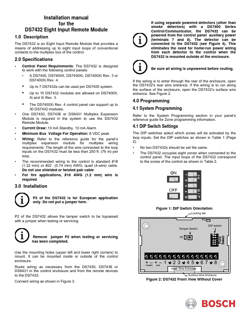
Installation manualfor theDS7432 Eight Input Remote Module1.0 DescriptionThe DS7432 is an Eight Input Remote Module that provides ameans of addressing up to eight input loops of conventionalcontacts to the multiplex bus of the control.2.0 Specifications• Control Panel Requirements: The DS7432 is designedto work with the following control panels:• A DS7400, DS7400X, DS7400Xi, DS7400Xi Rev. 3 orDS7400Xi Rev. 4.• Up to 7 DS7432s can be used per DS7400 system.• Up to 15 DS7432 modules are allowed on DS7400X,Xi and Xi Rev. 3.• The DS7400Xi Rev. 4 control panel can support up to30 DS7432 modules.• One DS7430, DS7436 or DS9431 Multiplex ExpansionModule is required in the system to use the DS7432Remote Module.• Current Draw: 10 mA Standby, 10 mA Alarm•Minimum Bus Voltage For Operation: 8 VDC peak• Wiring:Refer to the reference guide for the panel’smultiplex expansion module for multiplex wiringrequirements. The length of the wire connected to the loopinputs on the DS7432 must be less than 250 ft. (76 m) perloop.• The recommended wiring to the control is standard #18(1.22 mm) or #22 (0.74 mm) AWG, quad (4-wire) cable.Do not use shielded or twisted pair cable.• For fire applications, #18 AWG (1.2 mm) wire isrequired.3.0 InstallationP3 of the DS7432 is for European applicationonly. Do not put a jumper here.P2 of the DS7432 allows the tamper switch to be bypassedwith a jumper when testing or servicing.Remove jumper P2 when testing or servicinghas been completed.Use the mounting holes (upper left and lower right corners) tomount. It can be mounted inside or outside of the controlenclosure.Route wiring as necessary from the DS7430, DS7436 orDS9431 in the control enclosure and from the remote devicesto the DS7432.Connect wiring as shown in Figure 3.If using separate powered detectors (other thansmoke detectors) with a DS7400 SeriesControl/Communicator, the DS7432 can bepowered from the control panel auxiliary power(terminals 7 and 8). The detector can beconnected to the DS7432 (see Figure 4). Thiseliminates the need for home-run power wiringfrom each detector to the control when theDS7432 is mounted outside of the enclosure.Be sure all wiring is unpowered before routing.If the wiring is to enter through the rear of the enclosure, openthe DS7432's rear wire entrance. If the wiring is to run alongthe surface of the enclosure, open the DS7432's surface wireentrance. See Figure 2.4.0 Programming4.1 System ProgrammingRefer to the System Programming section in your panel’sreference guide for Zone programming information.4.1 DIP Switch SettingsThe DIP switches select which zones will be activated by theloop inputs. Set the DIP switches as shown in Table 1 (Page2).• No two DS7432s should be set the same.• The DS7432 occupies eight zones when connected to thecontrol panel. The input loops of the DS7432 correspondto the zones of the control as shown in Table 2.Figure 1: DIP Switch OrientationFigure 2: DS7432 Front View Without CoverTable 1: DIP Switch SettingsT able 2: Loop/Zone Number RelationshipPoints 249-256 are not available for DS9400 use.POWER BUSTo control panel 12VDC power terminals:DS7400, terminals 7 and 8, Fig. 4DS9400, terminals RA and BA, Fig. 5To DS7430, DS7436 or DS9431 MUX BUS Terminals (see Figure 4 or 5)When used with a DS9431 , power isOpen (N/O) contacts must be used.Initiating circuits are Class BFigure 3: Wiring the DS7432 with Separate Powered DetectorsPower -connected.Figure 4: 4-Wire Smoke Detector Wiring for the DS7432 and DS7400Xi Control/Communicator.© Bosch Security Systems B.V., 20202020.05Torenallee 49 5617 BA, Eindhoven, Netherlands DS7432 Installation manualDS9400 FACPground paths, do not connect wiring to the BUS (-) terminal on this module for fire connected.Figure 5: 4-Wire Smoke Detector Wiring for the DS7432 and DS9400 Series FACPFor UL Listed fire installations, Normally Open (N/O) contacts must be used.。
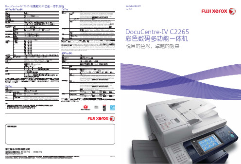
DC-IVC2265
韩文字体 ( Myungio、Gothic、Round Gothic、Graphic、Kungso、Saemul )
PostScript® 3TM
136种欧洲字体
(选配)
TC/SC Additional Font ROM Kit: China Font (ShuSong、KaiTi、HeiTi、FangSong)
DocuCentre-IV 2265 彩色数码多功能一体机规格
基本功能/复印功能(选配)
项目 类型 内存容量*1 硬盘容量*2 彩色功能 扫描分辨率 打印分辨率 色阶/可打印色彩 预热时间*3
原始纸张尺寸
输出纸张尺寸 最大
最小
图像损失
输出纸张重量*4 纸盘
手送纸盘
首页输出时间 黑白
彩色
缩放倍率
等倍率
(选配)
Windows Server® 2008 (x86), Windows® 7, Windows® XP Professional x64
Edition, Windows Server® 2003 x64 Editions, Windows Vista(x64)®, Windows
Server® 2008 (x64) ,Windows® 7 (x64) ,Windows Server® 2008 R2 (x64) 英语版
注意:
1) 一旦主机的内存(硬盘等)发生故障,接收的数据、保存的数据、登记设置信息的数据等有可能会丢失。 由于数据丢失引起的损害,本公司一概不负责赔偿,请事先知悉。
2) 保修用的功能性零部件的最低保存期限为设备主机停产后7年。
打印功能
项目 操作系统*3
内置字体 仿真 接口
内容
PCL6驱动 (标配)
Konica Minolta MFP设备实地指南说明书
⽤⼾⼿册⽂档仅供参考,有关最新信息,请参考联机帮助。
修订⽇期: 2023年09⽉01⽇⽬录实地指南概观安装要求⼊⻔预安装在iSeries设备上使⽤快速安装程序故障排除实地指南概观MarketPlace是⼀站式销售平台,可在MFP设备上运⾏应⽤程序和许可证.该帮助部分提供有关:要求安装程序下载和设置预安装在iSeries设备上安装要求MFP固件要求MFP系列需要的选购件需要的固件C554e, C364e, 554e, 364e LK-101v3 i-Option许可证组件(Web浏览器)需要扩展内存安装了硬盘安装了i-Option ROMG20-K6C754e, 754e LK-101v3 i-Option许可证组件(Web浏览器)需要扩展内存安装了硬盘安装了i-Option ROMG20-K7C368, 287, C287, 558, C658, 958启⽤了Web浏览器需要扩展内存(可能包含在基础产品中)安装了硬盘安装了i-OptionROMG00-54(或更⾼版本)4750LK-101v3 i-Option许可证组件(Web浏览器)安装了硬盘安装了i-Option ROMA6F730G07058-W99C3850FS LK-101v3 i-Option许可证组件(Web浏览器)需要扩展内存安装了硬盘安装了i-Option ROMA3GN30G0705-W99C364, C554, C754, 754LK-101v3 i-Option许可证组件(Web浏览器)需要扩展内存安装了硬盘安装了i-Option ROMGB2-K5您可能还需要将软开关#223设为1.检查固件⽂档了解功能版本开关(SW #25)的正确值.注意:柯尼卡美能达MarketPlace不可与安装在MFP上的第三⽅控制器(例如,Fiery控制器)结合使⽤.此外,柯尼卡美能达将不兼容安装了SC-508安全组件的设备.IWS设置要求请确保通过以下设置在MFP上启⽤IWS设置:IWS设置 = ON端⼝号(Web服务器) = 8090端⼝号(应⽤程序安装) = 8091连接IWS应⽤到⽹络 = 允许MFP⽹络要求要通过柯尼卡美能达MarketPlace安装和删除应⽤程序,必须允许MFP通过端⼝443连接⾄.对于安装好的应⽤程序,可能还需要其它⽹络访问.⼊⻔下载安装程序柯尼卡美能达技术⼈员可从⽀持⻚⾯的媒体选项卡访问柯尼卡美能达MarketPlace.在登录到柯尼卡美能达MarketPlace⽹站后,执⾏以下操作:1. 在顶部导航栏上选择⽀持.2. 选择Media媒体选项卡.3. 选择并下载MarketPlace安装程序.安装安装程序柯尼卡美能达MarketPlace安装程序安装向导将可指导您完成安装过程.请执⾏以下操作:1. 双击安装程序安装可执⾏⽂件.将显⽰柯尼卡美能达MarketPlace安装程序安装向导窗⼝.在向导窗⼝上,单击下⼀步按钮.2. 阅读⽤⼾许可协议.完成时,单击我接受协议单选按钮,然后单击下⼀步按钮.3. 显⽰“准备安装”窗⼝,列出您的⽬标位置和开始菜单⽂件夹.单击安装按钮.4. 完成安装安装程序后,将显⽰“完成柯尼卡美能达MarketPlace安装程序安装向导”窗⼝;单击完成按钮,向导将会关闭.(可选)配置安装程序 - MarketPlace菜单打开柯尼卡美能达MarketPlace安装程序并选择MarketPlace.有以下选项可⽤:启⽤调试⽇志记录 - 在安装程序出现问题时启⽤调试⽇志记录.代理配置 - 允许通过代理服务器与柯尼卡美能达MarketPlace通信.有以下选项可⽤:启⽤代理 - 选中此复选框为柯尼卡美能达MarketPlace启⽤代理服务器⽀持.在代理服务器地址字段中输⼊代理服务器地址,并在代理服务器端⼝字段中输⼊端⼝号.启⽤代理⾝份验证 - 选中此复选框在代理服务器上启⽤⾝份验证.在⽤⼾字段中输⼊⽤⼾名,并在密码字段中输⼊密码.完成时,单击保存按钮.语⾔ - 允许⽤⼾为柯尼卡美能达MarketPlace安装程序应⽤选择⼀种语⾔.柯尼卡美能达MarketPlace安装程序提供以下语⾔:捷克语荷兰语英语法语(⽐利时)法语(法国)德语⽇语俄语西班⽛语乌克兰语(可选)配置安装程序 - 帮助菜单打开柯尼卡美能达MarketPlace安装程序并选择帮助.有以下选项可⽤:检查更新 - 检查安装程序的最新更新.查看安装指南 - 打开PDF版本的柯尼卡美能达MarketPlace安装指南.客⼾反馈 - 打开安装程序的柯尼卡美能达质量反馈代理.反馈代理收集请求⽀持时所必需的⽇志⽂件.关于 - 显⽰关于安装程序的版本和制作信息.预安装在iSeries设备上MarketPlace已预先安装在以下设备上.系列C750i, C650i, C550i, C450i, C360i, C300i, C250i750i, 650i, 550i, 450i, 360i, 300iC4000i, C4050i, C3350i4750i, 4700i, 4050i要访问MarketPlace,请在多功能机上选择MarketPlace应⽤程序按钮,如下图所⽰:根据您所在地区的不同,MarketPlace应⽤程序可能已经安装在MFP上并可以使⽤。
柯美C6500彩色高速复印机介绍
柯美C6500产品介绍产品规格bizhub PRESS C6500主机规格参数表型号名称bizhub PRESS C6500类型落地式颜色支持全彩色分辨率扫描600×600dpi打印1,200(相当于3,600)×1,200dpi 内存DIMM 512MB×6硬盘160GB×6SATA(选购)色阶256级原稿类型纸张、书本、三维物体最大原稿尺寸最大A3或11"×17"纸张尺寸SRA3、A3、B4、SRA4、A4、SRA4S1、A4S1、B5、B5S1、A5S1、12" × 18"、11" × 17"、8.5" × 11"、不规则尺寸(330 × 487至140 × 182mm)无效图像区域上部边距4mm或以下,下部边距4.5mm或以下右侧/左侧边距3mm或以下预热时间420秒或更少首页复印时间(A4)彩色C7000: 7.6秒或更少,C6000:7.8秒或更少黑白C7000: 5.9秒或更少,C6000:6.0秒或更少打印速度*1(A4/Letter)彩色C7000: 71/70页/分钟,C6000:60/60页/分钟黑白C7000: 71/70页/分钟,C6000:60/60页/分钟复印缩放倍率固定倍率1:1偏差少于±0.5%固定放大1:1.154/1.224/1.414/2.000固定缩小1:0.866/0.816/0.707/0.500可设定倍率可自定义3种缩放可以1%为增幅在25%至400%之间调节纸张容量标配1,500张(80 g/m*2)纸张克重*264 -300 g/m2多张连续复印1至9999张自动双面标配电源要求220至240V 20A(50至60Hz)功耗低于4.6kW尺寸[宽] × [深] × [高]*3760 × 992.7 × 1,075.6mm (30" × 39" × 42-1/4") 重量353kg(778-1/2 lb)上标说明:∙*1.打印速度可能因纸张克重而异。
柯尼卡美能达打印机维修配件及耗材技术规格及其他要求
4
IOO
C221
黑色鼓组件
个
2
101
C221
鼓组件(红)
个
2
102
C221
鼓组件(黄)
个
2
103
C221
鼓组件(蓝)
个
2
104
C221
显影仓黑色
个
2
105
C221
显影仓红色
个
2
106
C221
显影仓黄色
个
2
107
C221
显影仓蓝色
个
2
108
C221
转印带
个
1
109
C221
废粉盒
个
1
no
654e
美能达原装TN712碳粉*(B654)
45
主板
1106/1136/1108/1108
套
1
46
主板维修
1106/1136/1108/1108
套
1
47
加热组件
1106/1136/1108/1108
套
1
48
激光器
1106/1136/1108/1108
套
1
49
传动组件
1106/1136/1108/1108
套
1
50
主板
1.11121E
套
1
51
主板维修
magicolor1700W
黄色粉盒
个
1
119
magicolor1700W
红色粉盒
个
1
120
magicolor1700W
蓝色粉盒
个
1
惠普 Color LaserJet Pro M153-M154 用户指南说明书
ห้องสมุดไป่ตู้
目录
1 打印机概述 ............................................................................................................................................................................................... 1 打印机视图 .............................................................................................................................................................................. 2 打印机前视图 ..................................................................................................................................................... 2 打印机后视图 ..................................................................................................................................................... 3 控制面板视图 ..................................................................................................................................................... 4 打印机规格 .............................................................................................................................................................................. 5 技术规格 .............................................................................................................................................................. 5 支持的操作系统 ................................................................................................................................................. 5 移动打印解决方案 ............................................................................................................................................ 7 打印机尺寸 .......................................................................................................................................................... 7 功耗、电气规格和噪声发射 .......................................................................................................................... 8 操作环境范围 ..................................................................................................................................................... 8 打印机硬件设置与软件安装 ............................................................................................................................................... 9