安全泄压阀说明书
500X泄压持压阀使用及如何调试说明
500X—10/16/25/40(C)泄压/持压阀使用说明书可拉伐阀门(上海)有限公司一、产品概述500X—10/16/25/40(C)泄压/持压阀是一种隔膜型水力自动控制阀门。
该产品主要由主阀、泄压/持压导阀、球阀、止回阀、压力表等构造而成。
主要特点是既可以当作泄压阀,也可以当作持压阀。
作为泄压阀时可将供水管道中超过泄压/持压导阀安全设定值之上的压力释放,维持管道中的压力于安全设定值以下,以防止管道中的高压或突压毁损管道或其它设备;作为持压阀时可维持主阀上游供水压力于某一设定值以上,以保证主阀上游供水区的压力。
此阀可用于高层建筑消防测试循环系统及工业、农业、生活等给水、排水系统管道中,保持水压和保护管道及其设备。
二、性能参数公称压力PN(MPa)1.01.62.5 4.0工作压力(MPa)1.01.62.5 4.0试验压力壳体试压(MPa)1.52.43.8 6.0密封试压(MPa)1.11.82.5 4.4泄压调节范围(MPa)0.2~0.80.2~1.20.4~2.00.4~3.0持压调节范围(MPa)0.2~0.80.2~1.20.4~2.00.4~3.0泄压/持压压力波动相对于进口压力的误差范围±10%适用介质无杂物的清水、污水介质适宜温度0℃~80℃三、主阀上制控管路、元件布置示意图四、工作原理作泄压阀:当泄压/持压导阀调整为泄压状态时,主阀进口端的一部分水通过单向止回阀、泄压/持压导阀,流向主阀控制室。
此时主阀处于关闭状态。
当进口压力超过泄压/持压导阀设定的安全值时,泄压/持压导阀开启,主阀阀瓣开启,使管路泄压。
当压力恢复到安全值时,泄压阀门自动关闭。
作持压阀:当泄压/持压导阀调整为持压状态时,只要主阀进口水压低于导阀设定值,导阀即关闭。
主阀控制室升压,主阀关闭。
当主阀上游供水压力超过导阀设定压力时,持压导阀才能打开,控制室降压主阀开启,开始排水,即保持了上游水压。
这时,主阀控制腔内的压力与主阀进口端的压力相等。
安全泄压阀-AX742X安全泄压阀

当前位置:上海工洲阀门有限公司首页>> 产品展示>>水利控制阀>>泄压阀>>安全泄压阀水力控制阀系列价格供用户或设计院工程项目做预算一、阀门的选型步骤1.明确阀门在设备或装置中的用途,确定阀门的工作条件:适用介质、工作压力、工作温度等等。
2.确定与阀门连接管道的公称通径和连接方式:法兰、螺纹、焊接等。
3.确定操作阀门的方式:手动、电动、电磁、气动或液动、电气联动或电液联动等。
4.根据管线输送的介质、工作压力、工作温度确定所选阀门的壳体和内件的材料:灰铸铁、可锻铸铁、球墨铸铁、碳素钢、合金钢、不锈耐酸钢、铜合金等。
5.确定阀门的型式:闸阀、截止阀、球阀、蝶阀、节流阀、安全阀、减压阀、蒸汽疏水阀、等。
6.确定阀门的参数:对于自动阀门,根据不同需要先确定允许流阻、排放能力、背压等,再确定管道的公称通径和阀座孔的直径。
7.确定所选用阀门的几何参数:结构长度、法兰连接形式及尺寸、开启和关闭后阀门高度方向的尺寸、连接的螺栓孔尺寸和数量、整个阀门外型尺寸等。
8.利用现有的资料:阀门产品目录、阀门产品样本等选型适当的阀门产品。
二、阀门的选型依据1.所选用阀门的用途、使用工况条件和操纵控制方式。
2.工作介质的性质:工作压力、工作温度、腐蚀性能,是否含有固体颗粒,介质是否有毒,是否是易燃、易爆介质,介质的黏度等等。
3.对阀门流体特性的要求:流阻、排放能力、流量特性、密封等级等等。
4.安装尺寸和外形尺寸要求:公称通径、与管道的连接方式和连接尺寸、外形尺寸或重量限制等。
⑤对阀门产品的可靠性、使用寿命和电动装置的防爆性能等的附加要求。
(在选定参数时应注意:如果阀门要用于控制目的,必须确定如下额外参数:操作方法、最大和最小流量要求、正常流动的压力降、关闭时的压力降、阀门的最大和最小进口压力。
)根据上述选型阀门的依据和步骤,合理、正确地选型阀门时还必须对各种类型阀门的内部结构进行详细了解,以便能对优先选用的阀门做出正确的抉择。
安全阀使用说明

安全阀使用说明
1、使用上的注意说明
因为要求该安全阀在低压力下工作,所以阀座与阀体的接触面是经过精密加工的,如果有异物附着在阀座周围,阀体动作时,异物就会被吸附到接触面上,由此形成阀体泄露的原因。
另外,请注意安全阀在搬运过程中是否受到冲击,这也是造成阀体泄露的原因。
2、安全阀的设定方法
原理:当负荷超过安全阀的设定压力时,安全阀开启,由此防止风机故障。
3、设定方法:
(1)一边观察压力表,一边旋紧闸阀,使压力超过设定压力的10%左右。
(2)松开锁定螺母,按逆时针方向旋转调节螺杆,直至从安全阀排出空气为止。
(3)若旋紧闸阀的过程中,尚未到达设定压力,安全阀已排除空气,请再一次按顺时针方向旋转调节螺杆,直至旋至不再排出空气位置,再逆时针方向旋转,恰好在排出空气为止(顺时针旋转,设定压力变高;逆时针旋转,设定压力变低)。
(4)旋紧锁定螺母和调节螺杆。
(5)松开闸阀,降低压力,使安全阀不再排气。
(6)检查安全阀是否在设定压力下工作,再次旋紧闸阀提高压力。
(7)注意:实际在排气侧有负荷时(曝气槽内达到既定水位)若闸阀全开时,设定压力比实际负荷高约10%左右。
63EG 型泄压阀或背压阀 说明书

63EG 型和 1098-63EGR 型D 100315X C N 2指导手册资料号 51102008 年 11月63EG 型泄压阀或背压阀简介手册内容本手册为带有 6358, 6358B, 6358EB 型或 6358EBH 型指挥器的 63EG 型泄压阀或背压阀、以及带有 6358B 型指挥器的 1098-63EGR 型泄压阀提供了的操作说明和零件清单。
对于选配的指挥器用过滤器 252 型或 P590 系列,以及与其配合使用的装置的操作说明和零件清单,可在另外单独的手册中找到。
产品说明63EG 型和 1096-63EGR 型指挥器作用式泄压阀可用于液体和气体的场合。
63EG 型也适用于限流背压或旁路应用工况。
这两种主阀都采用了可快速更换阀内件的构造,便于快速维护。
技术规格技术规格章节及表 1 到 3 列出了各种 63EG 型和 1098-63EGR 型的技术规格。
出厂时,调压器的技术规格印在主阀的铭牌上。
对于 1098-63EGR 型, 技术规格印在执行机构的上部阀膜箱体。
指挥器的控制弹簧作用范围印在指挥器弹簧箱体上,指挥器限流孔代码用一个字母表示,它印在指挥器阀体底部,靠近旁路出口: S 代表红色标准直径限流孔 (钻孔尺寸 57),L 代表蓝色大直径限流孔 (钻孔尺寸 47),用于液体的场合,或用 H 代表黄色小直径 (钻孔尺寸 70),用于高增益限流孔。
指挥器说明以下的指挥器配置可用于 63EG 型或 1098-63EGR 型泄压阀或背压阀。
泄压阀6358B, 6358EB 型指挥器或 6358EBH 型泄压指挥器可与泄压阀配合使用。
当泄压阀运行时,指挥器不断地排放压力。
当入口压力低于设定压力时,指挥器停止排图 1. 63EG 型泄压阀或背压阀W6955图 2. 1098-63EG 型泄压阀W3003-1*63EG 型和 1098-63EGR 型2技术规格可供配置带 6358 系列指挥器的 63EG 型带 6358B 型指挥器的 1098-63EG 型主阀阀体和端口连接方式(1, 2)主阀阀体尺寸, 英寸 (DN)端口连接方式和额定值铸铁钢或不锈钢1, 2 (25, 50)NPT , CL125B FF , 或 CL250B RF 法兰连接NPT , BWE, SWE, CL150 RF , CL300 RF , CL600 RF , 或 PN 16/24/40 法兰连接2, 3, 4, 6, 8 x 6(50, 80, 100, 150,200 x 150)CL125B FF , 或CL250B RF 法兰连接BWE, CL150 RF ,CL300 RF , CL600 RF , 或 PN 16/24/40 法兰连接最大泄压 (入口(3)) 压力(2)63EG 型: 400 psig (27,6 bar)1098-63EGR 型: 82 psig (5,6 bar)最大执行机构压力(2) (标准尺寸 40, 仅适用于 1098-63EGR 型)最大设定压力(4): 65 psig (4,5 bar) 最大工作压力(3): 75 psig (5,2 bar)最大紧急情况压力: 82 psig (5,6 bar)设定泄压/背压控制范围(4) 见表 2主阀端口直径和阀塞行程阀体尺寸,英寸 (DN)端口直径, 英寸 (毫米)阀塞行程, 英寸 (毫米)1 (25)2 (50) 1.312.38 (33) (60)0.751.13 (19) (29)3 (80)4 (100) 3.384.38 (86) (111) 1.502.00 (38) (51)6 和 8 x 6 (150 和 200 x 150)7.19 (183)2.00 (51)主阀流量特性线性 (标准) 或 Whisper ®Trim III (可选)主阀流量方向上部通过阀座垫圈流入和外部通过阀笼流出温度范围(2)腈橡胶 (NBR):-20° 至 180°F (-29° 至 82°C) 氟橡胶 (FKM):0° 至 300°F -18° 至 149°C)水温限制在 0° 至 180°F (-18° 至 82°C ) 三元乙丙橡胶 (EPDM):-20° 至 275°F (-29° 至 135°C)可选项• 铝或不锈钢制的 252 型指挥器用过滤器 • 黄铜制的 P594-1 型过滤器 • 压力计(5)大致重量 (包括指挥器) 63EG 型1 英寸 (DN 25): 35 磅 (16 公斤)2 英寸 (DN 50): 55 磅 (25 公斤)3 英寸 (DN 80): 95 磅 (43 公斤)4 英寸 (DN 100): 145 磅 (66 公斤) 6 英寸 (DN 150): 330 磅 (150 公斤)8 x 6 英寸 (DN 200 x 150): 670 磅 (304 公斤) 1098-63EGR 型1 英寸 (DN 25): 65 磅 (29 公斤)2 英寸 (DN 50): 85 磅 (39 公斤)3 英寸 (DN 80): 125 磅 (57 公斤)4 英寸 (DN 100): 175 磅 (79 公斤)6 英寸 (DN 150): 360 磅 (163 公斤)8 x 6 英寸 (DN 200 x 150): 700 磅 (318 公斤)1. 通常也提供 DIN (或其它) 额定值和端口连接: 请向费希尔公司销售服务部门或销售代理商咨询。
安全泄压阀技术说明

安全泄压阀技术性能说明一、用途本阀门安装在水泵出口端,顺序实现缓慢开启、全开、速闭、缓闭等功能。
本产品用于高层建筑给水系统和其它给水系统的水泵出口管路上,防止和减弱水泵启闭时管线的水锤水击,防止水倒流保护水泵,维护管路安全。
二、型号、规格、技术参数说明型号:AX742X-10技术参数:1、公称压力:1.0MPa;2、规格:DN65-DN10003、动作压力:不小于0.05MPa4、适用介质:水5、适用温度:0-80度6、缓闭时间:3-60秒7、泄漏量为零。
8、阀门壳体强度实验压力: 1.5倍公称压力9、阀门密封实验压力: 1.1倍公称压力10、表面处理采用环氧树脂防腐涂料喷涂。
阀门系统组成工作原理:1.安全泄压持压阀利用设定调压导阀弹簧压力和调节针型阀开度设定出口压力,并通过接管系统和控制室的反馈作用来稳定出口压力。
AX742X安全泄压/持压阀利用针型调节阀、导阀进行水压自力控制,不需要附加其它装置和能源,维护保养简便,受进口压力和流量影响小,压力控制准确度高,减压稳压可靠。
2.当管道从进水端给水时,水流过针阀进入主阀控制室,出口压力通过导管作用到导阀上,当出口压力高于导阀设定值时,导阀关闭,控制室停止排水,此时主阀控制室内压力升高并关闭主阀,出口压力不再升高。
3.当出口压力降到导阀设定压力时导阀开启,控制室向下游排水。
由于导阀的排水量大于针阀的进水量,主阀控制室压力下降,进口压力使主阀开启。
稳定状态下,控制室进水、排水相同,开度不变,出口压力不变。
调节导阀弹簧即可设定出口压力。
选用要点:(1)工程式中应用的水力控制阀是经过制造厂检验合格,各种标识齐全,技术资料符合要求的产品。
(2)根据功能要求,选择阀门种类,再根据管道输送介质、温度、建筑标准和业主要要求等,确定阀门的阀体和密封部位的材质。
常用的阀体材料有铸铁、铜铁、铜、塑料等。
常用的密封面和衬里材料有铜合金、塑料、钢、硬质合金、橡胶等。
阀体材料应与管道材料相匹配。
背压泄压阀说明书
目录第1节 简介概论特点工作原理型号编号外形尺寸技术参数第2节 安装开箱安全措施安装第3节 压力设定与调整准备工作背压阀的压力设定泄压阀的压力设定第4节 维护备件设备维修第5节故障查询第6节部件第1节简介一、 概论当设备出现故障或化学管路堵塞出现过压时,VS系列隔膜泄压阀可用来保护可调容积泵和其他设备,VB系列背压阀在泵运行时在排出管路中提供一个比吸入管路更高的压力。
这确保了在吸入行程时不会有流体由于惯性或虹吸作用流入排出管路。
这些阀在泵运行时还可作为防虹吸阀。
二、 特点1、高可靠性/低成本2、PTFE/EPDM复合膜片3、泄压阀0~1.0Mpa可调背压阀0~0.3Mpa可调4、可安全释放排泄至吸入管路或溶液箱中5、背压阀具有防虹吸功能6、防松调节螺钉7、机加工结构,坚固三、 工作原理VS系列隔膜式泄压阀在正常情况下,泄压阀不泄放,内部弹簧压紧支承块,使隔膜顶住阀座将排放口密封,当系统压力高于阀门设定压力时,化学品流出并回流至化学容器或计量泵吸入管路(在现场可通过调节螺钉在0~1.0Mpa范围内设置压力,泄放压力应设置高于系统压力约0.1Mpa。
建议在管线上安装压力表以便现场调整泄放压力)。
膜片保持顶启,直到系统压力再次下降到阀门设定压力以下,弹簧将隔膜压下封住排放口,继续正常的运行。
VB系列隔膜式背压阀通过抵消吸入惯性和防止工艺压力低于吸入压力时的系统虹吸,消除由投加点压力波动引起的投加量变化,在计量泵排出端保持一定的压力以确保精确计量。
(在现场可通过调节螺钉在0~0.3Mpa范围内设置背压)。
在计量泵的排出行程压力作用于隔膜,将其顶启,而使计量泵的液体通过。
当计量泵的排出流量减少至0时(吸入行程),弹簧使隔膜复位,将计量泵出口和阀门之间的低压液体分开,这样就保证了泵出口止回阀恒定的正压。
四、 型号编码五、 外形尺寸六、 技术参数1、工作压力:1.0Mpa2、工作温度:PVC、PVDF阀体 max60℃316SS阀体 max90℃3、压力设置范围:VS 0~1.0MpaVB 0~0.3Mpa出厂设定:VS 0.5MpaVB 0.2Mpa(200L/h流量状态)4、工作性能曲线(参见背压阀,泄压阀流量压力曲线图)第2节安装一、开箱当承运人接受货物时,货物就从工厂发出,转交到用户,一切在运输过程中发生的损坏用户都应立即通知承运人并要求索赔,在正式接收前,仔细检查运输包装,确认在运输过程中没有发生损坏,打开包装,确认所有附件都完好,数量正确,并与装箱单核对无误。
安全阀泄压阀知识
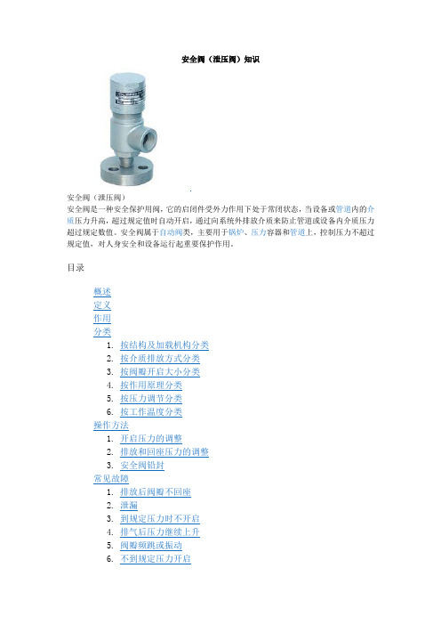
安全阀(泄压阀)知识安全阀(泄压阀)安全阀是一种安全保护用阀,它的启闭件受外力作用下处于常闭状态,当设备或管道内的介质压力升高,超过规定值时自动开启,通过向系统外排放介质来防止管道或设备内介质压力超过规定数值。
安全阀属于自动阀类,主要用于锅炉、压力容器和管道上,控制压力不超过规定值,对人身安全和设备运行起重要保护作用。
目录弹簧式安全阀手册(2张)定义安全阀(Safety Valve,又称泄压阀Relief Valve)是根据压力系统的工作压力(工作温度)自动启闭,一般安装于封闭系统的设安全阀备或管路上保护系统安全。
当设备或管道内压力或温度超过安全阀设定压力时,自动开启泄压或降温,保证设备和管道内介质压力(温度)在设定压力(温度)之下,保护设备和管道正常工作,防止发生意外,减少损失。
作用安全阀在系统中起安全保护作用。
当系统压力超过规定值时,安全阀打开,将系统中的一部分气体/流体排入大气/管道外,使系统压力不超过允许值,从而保证系统不因压力过高而发生事故。
密封全铜安全阀分类安全阀安全阀结构主要有两大类:弹簧式和杠杆式。
弹簧式是指阀瓣与阀座的密封靠弹簧的作用力。
杠杆式是靠杠杆和重锤的作用力。
随着大容量的需要,又有一种脉冲式安全阀,也称为先导式安全阀,由主安全阀和辅助阀组成。
当管道内介质压力超过规定压力值时,辅助阀先开启,介质沿着导管进入主安全阀,并将主安全阀打开,使增高的介质压力降低。
安全阀的排放量决定于阀座的口径与阀瓣的开启高度,也可分为两种:微启式开启高度是阀座内径的(1/15)~(1/20),全启式是(1/3)~(1/4)。
此外,随着使用要求的不同,有封闭式和不封闭式。
封闭式即排出的介质不外泄,全部沿着规定的出口排出,一般用于有毒和有腐蚀性的介质。
不封闭式一般用于无毒或无腐蚀性的介质。
按结构及加载机构分类安全阀结构图按其整体结构及加载机构的不同可以分为重锤杠杆式、弹簧式和脉冲式三种。
1.重锤杠杆式安全阀重锤杠杆式安全阀是利用重锤和杠杆来平衡作用在阀瓣上的力。
SPR系列手动泄压阀说明书

Instructions and Operations ManualforSPR-SeriesManual Pressure Relief ValveDixon SanitaryN25 W23040 Paul Road • Pewaukee, WI 53072ph: 800.789.1718 • fx: 800.789.4046Read and understand this manual prior to installing, operating or servicing this valve2Manual Pressure Relief Valve I & O Manual800.789.1718Table of ContentsSafety (3)Care of Stainless Steel (4)Technical Specifications .......................................................................................................................................................................5Installation and Start-Up ....................................................................................................................................................................6-7General Maintenance (8)Assembly and Disassembly (9)Dimensions (10)Bill of Materials (11)Troubleshooting (12)Warranty .............................................................................................................................................................................................13 This manual contains installation, operation, cleaning, repair instructions, model numbering structure and a parts list for the Dixon Sanitary SPR-Series Manual Pressure Relief Valves. Please read and understand this manual prior to installing, operating or servicing this valve.The Dixon Sanitary SPR-Series Manual Pressure Relief Valve is a compact manually adjustable clean-out-of-place valve assembly used in sanitary process systems to protect pressure sensitive equipment. The valve utilizes three different springs with three unique spring constants to cover set pressure ranges of 10-50 PSI, 50-100 PSI or 100-300 PSI.The high-quality valve body is precision machined from solid 316L bar. Valve bodies are available in two different body configurations with a variety of different connection options.IntroductionSafety InformationDo’s and Don’ts•Do read and understand these instructions before installing or using the SPR-Series pressure relief valve.•Do use Dixon spare parts when replacing components of the relief valve.•Do Not attempt to service the relief valve while under pressure.•Do Not place the relief valve in an application where the service ratings are exceeded.•Do Not attempt to modify the relief valve assembly as it may compromise the integrity of the assembly and will void all warranties.Safety Precautions When Installing Relief Valve•Do relieve product line pressure before attempting to install relief valve.•Do install discharge piping that allows discharged product to flow safely to a drain or bypass.•Do Not install a damaged relief valve assembly.•Do Not install relief valve between damaged clamp ferrules.Safety Precautions When Relief Valve is in Operation•Do monitor the relief valve assembly for any sign of leakage.•Do check all clamp assemblies often to ensure that they have not loosened from vibration.•Do Not stand in the vicinity of the discharge outlet while the relief valve is in operation.•Do Not attempt to loosen any clamp assemblies while the relief valve is in operation.•Do Not attempt to perform any type of service or adjustment to the relief valve during operation.Safety Precautions When Servicing the Relief Valve•Do drain piping completely before servicing.•Do vent line to relieve any pressure.•Do relieve spring force before attempting to remove body clamp.•D o use caution and wear protective clothing if relief valve has been used in applications using acids or other chemicals that may be harmful.Manual Pressure Relief Valve I & O Manual800.789.17183Care of Stainless SteelThe stainless steel components in Dixon Sanitary equipment are machined, welded and assembled by skilled craftsmen using manufacturing methods that preserve the corrosion-resistant quality of the stainless steel.Retention of corrosion-resistant qualities under processing conditions requires regular attention to the precautions listed below.1.R egularly check all electrical devices connected to the equipment for stray currents caused by improper grounding, damagedinsulation or other defects. Corrosion: Pitting often occurs when stray currents come in contact with moist stainless steel.2.N ever leave rubber mats, fittings, wrenches, etc. in contact with stainless steel. Corrosion: Pitting or galvanic action. Objectsretard complete drying, preventing air from reforming the protective oxide film. Galvanic corrosion occurs when two dissimilar metals touch when wet.3.I mmediately rinse equipment after use with warm water until the rinse water is clear. Clean the equipment (manual or CIP)as soon as possible after rinsing. Corrosion: discoloration, deposits, pitting. Product deposits often cause pitting beneath the particles.4.U se only recommended cleaning compounds. Purchase chemicals from reputable and responsible chemical manufacturersfamiliar with stainless steel processing equipment, they continuously check the effects of their products on stainless steel.5.U se cleaning chemicals exactly as specified by the manufacturer. Do not use excessive concentrations, temperatures or exposuretimes. Corrosion: Pitting, discoloration, stress cracks. Permanent damage often occurs from excessive chemical concentrations, temperatures or exposure times.6.F or manual cleaning, use only soft non-metallic brushes, sponges or pads. Brush with the grain on polished surfaces, avoidscratching the surface. Corrosion: Pitting, scratches. Metal brushes or sponges will scratch the surface and promote corrosion over a period of time. Metal particles allowed to remain on a stainless steel surface will cause pitting.7.U se chemical bactericides exactly as prescribed by the chemical manufacturer in concurrence with local health authority. Usethe lowest permissible concentration, temperature and exposure time possible. Flush immediately after bacterial treatment. In no case should the solution be in contact with stainless steel more then 20 minutes. Corrosion: Protective film destroyed. Chlorine and other halogen bactericides can destroy the protective film. A few degrees increase in temperature greatly increases chemical activity and accelerates corrosion.8.R egularly inspect the joints in pipelines. Be sure all connections are tight fitting without binding. Corrosion: Crevice corrosion.Small crevices caused by improperly seated gaskets will promote crevice corrosion. Stainless steel under stress will develop stress cracking especially in the presence of bactericides containing chlorine.9.R egularly inspect equipment for surface corrosion (i.e. pitting deposits, stress cracks, etc.). If deposit or color corrosion isdetected, remove it immediately using mild scouring powder and detergents. Rinse thoroughly and allow to air dry. Review production and cleaning procedures to determine the cause. Note: If corrosion is not removed, the protective film cannot be restored and corrosion will continue at an accelerated rate.800.789.17184Manual Pressure Relief Valve I & O Manual5Manual Pressure Relief Valve I & O Manual 800.789.1718Technical SpecificationsModelSet Pressure Range (PSI)Maximum Temperature Operating [Sterilization ‡]SPR-TC*1A10-50266°F [300°F]SPR-TC*2A0-100SPR-TC*3A0-300SPR-LC*1A10-50SPR-LC*2A0-100SPR-LC*3A0-300Materials:•Product contact parts: AISI 316L Stainless Steel •Product contact elastomers: EPDM or FKM •Non-Product contact components: 304 Stainless Steel • Finish: 32 R a on all product contact surfaces, other finishes availableConnections:• Clamp (Standard)• Bevel Seat, I-Line, and Weld ends availableSizes:• 1½" and 2"Specifications:* E = EPDM or V = FKM‡ Maximum 20 min6Manual Pressure Relief Valve I & O Manual800.789.1718Installation & Start UpUnpacking:Carefully unpack all parts of the valve and inspect for damage that may have occurred during shipment. Report any damage to the carrier immediately.The ports on the valve are protected with a plastic cover. If any covers are missing or damaged, inspect the ports on the valve thoroughly for any damage.Tools Needed:The following items will be needed for the installation.• Adjustable wrench• Food grade anti-seizeInstallation Orientation:The valve should be installed so that the fluid pressure is acting on the valve stem end. The following diagram should be followed when installing the valve for service. DANGER: Improper discharge piping from the valve could lead to serious injury. High pressure and potentially high temperature fluid exits the discharge port when valve opens. Piping should be installed so that the dischargedproduct flows safely to a drain.X7Manual Pressure Relief Valve I & O Manual 800.789.1718Setting Relief Pressure:1. I dentify which spring set the valve utilizes by referring to the tag located on the adjustable cap. Below is an example of the tag that will be located on the valve. There are three separate spring sets available for the SPR-Series pressure relief valve: Spring Set 1 (10-50 PSI), Spring Set 2 (50-100 PSI), and Spring Set 3 (100-300 PSI).Installation & Start Up3. O nce the desired set pressure has been determined, divide the set pressure by the PSI/Turn value obtained from the set pressure table. This will yield the number of required turns.4. U sing the numbered marks on the adapter (8) and the mark on the adjustable cap (12) as reference points, turn the adjustable cap(12) the calculated number of turns.5. U sing a pressure gauge on the inlet port of the valve, make any minor adjustments of the cap (12) needed to reach the exact pressure relief point desired.6. Confirm that the valve functions as desired before installing the valve for service.7. T ighten the locking nut (9) firmly against the adjustable cap (12) while keeping the adjustable cap stationary to avoid changing the relief pressure set point. Apply food grade anti-seize to the adapter threads if necessary.2. O nce the spring set has been identified, refer to the set pressure table below to obtain the values needed to calculate the numberof turns required for the desired set pressure.Spring SetMaximum Set Pressure (PSI)PSI / Turn Turns to Max Set Pressure 150114½2100214¾33001052¾General MaintenanceTo ensure that your Dixon SPR-Series pressure relief valve functions as designed, it is important to make sure that it is properly maintained. Only use genuine Dixon replacement parts when replacing any components of the SPR-Series pressure relief valve. DO NOT attempt to modify the valve in any way. Doing so will void all warranties and could result in injury.Cleaning the valve:1. Refer to the disassembly section of the manual and follow instructions to remove all product contact components of the valve.2. Inspect the product contact components of the valve for any signs of possible damage. Replace components as necessary.3. C lean all surfaces of the product contact components by manually brushing in a bath of cleaning solution (acid detergents or simple alkaline soda type detergents).4. After cleaning, rinse all components thoroughly with water.Note: Seat seal (2) must be replaced after removal5. R efer to the assembly section of the manual and follow instructions to properly reassemble the valve.6. R efer to the installation and start-up section of the manual for instructions on setting the valves relief pressure.800.789.17188Manual Pressure Relief Valve I & O ManualAssembly and Disassembly InstructionsAssembly:1. Take new seat seal (2) and install on the valve stem (3), making sure not to roll the seat seal.2. Place the body gasket (5) on the top inside lip of the valve body (1).3. Loosely place the valve stem and seat seal assembly (2 & 3) in the valve body (1).4. Slide the stainless stem holder (6) over the valve stem assembly (2 & 3).5. A pply food grade lubricant to the stem O-ring (7), and slide the O-ring over the stem (3) and press down securely into groove inthe stem holder (6).6. Slide the adapter (8) over the valve stem (3) and secure the adapter to the valve body (1) using the clamp (13).7. Place the washer (4) in the bottom of the adapter (8).8. Place the spring (10) on top of the washer (4) inside the adapter (8).9. Take the top cap (11) and place it on the spring (10).10. Apply food grade anti-seize to the threads on the adapter (8).11. Thread on the locking nut (9) and then the adjustable cap (12).12. Tighten the adjustable cap (12) until the top edge is flush with the face of the top cap (11).Disassembly:WARNING: Relieve fluid pressure in the line before disassembling the valve.1. Rotate adjustable cap (12) counter clockwise until the spring (10) is no longer under compression.2. L oosen and remove clamp (13) that secures the adapter (8) to the valve body (1). Remove the adapter, spring (10), andadjustable cap (12) assembly from the valve body.3. Remove the stem (3) and stem holder (6) from the valve body (1).4. Slide the stem holder (6) off of the valve stem (3) and remove the stem O-ring (7).5. Remove the body gasket (5) from the valve body (1).6. Using a pick, hook the seat seal (2), and remove it from the stem (3).Note: Seat seal (2) must be replaced after removalManual Pressure Relief Valve I & O Manual800.789.1718910Manual Pressure Relief Valve I & O Manual 800.789.1718DimensionsSizeA B 1½"2.69"9.18"2"3.04"9.84"11Manual Pressure Relief Valve I & O Manual800.789.1718Bill of MaterialsNumberPart QuantityMaterialPart Number1½"2'1L body 1316L SPR-LBDY150SPR-LBDY2001A T body 1316L SPR-TBDY150SPR-TBDY2002Seat seal 1FKM / EPDMSPR-SSV / SPR-SSE SPR-SSV / SPR-SSE 3Stem 1316L SPR-STEM150SPR-STEM2004Washer 1304SPR-WSHR SPR-WSHR 5Body gasket 1FKM / EPDM40IV150 / 40IE15040IV200 / 40IE2006Stem holder 1316L SPR-SH150SPR-SH2007Stem O-ring 1FKM / EPDMSPR-SOV / SPR-SOE SPR-SOV / SPR-SOE 8Adapter 1304SPR-ADPTR150SPR-ADPTR2009Locking nut 1304SPR-LNSPR-LN10Spring 1316L SPR-S50/SPR-S100/SPR-S300SPR-S50/SPR-S100/SPR-S30011Top cap 1304SPR-TOPCAP SPR-TOPCAP 12Adjustable cap1304SPR-ADJSTCAP SPR-ADJSTCAP 13Clamp130413IL-Q10015013IL-Q200TroubleshootingProblem Possible Cause Suggested Action Valve is leaking from detection port Damage to stem O-ring Replace stem O-ringValve is leaking between body andadapterDamage to body gasket Inspect & replace body gasketValve is relieving at pressures lower than the set pressure Locking nut loose which could allow theadjustable cap to moveTighten locking nutHigh pressure fluid is leaking past seat seal Obstruction between seal and body ordamaged seat sealInspect for obstructions and replace seatsealValve is not stroking properly when opening Washer is not installed under the springCheck to make sure the washer isinstalled according to the assemblyprocedureValve will not open at all Valve is installed in an improperorientationCheck installation section to make surethe valve is properly orientedAny other issue Contact a Dixon Sanitary applications Engineer12Manual Pressure Relief Valve I & O Manual800.789.1718Limited WarrantyDIXON VALVE AND COUPLING COMPANY (herein called "Dixon") warrants the products described herein, and manufactured by Dixon to be free from defects in material and workmanship for a period of one (1) year from date of shipment by Dixon under normal use and service. It's sole obligation under this warranty being limited to repairing or replacing, as hereinafter provided, at its option any product found to Dixon's satisfaction to be defective upon examination by it, provided that such product shall be returned for inspection to Dixon's factory within three (3) months after discovery of the defect. The repair or replacement of defective products will be made without charge for parts or labor. This warranty shall not apply to: (a) parts or products not manufactured by Dixon,the warranty of such items being limited to the actual warranty extended to Dixon by its supplier; (b) any product that has been subject to abuse, negligence, accident, or misapplication; (c) any product altered or repaired by others than Dixon; and (d) to normal maintenance services and the replacement of service items (such as washers, gaskets and lubricants) made in connection with such services. To the extent permitted by law, this limited warranty shall extend only to the buyer and any other person reasonably expected to use or consume the goods who is injured in person by any breach of the warranty. No action may be brought against Dixon for an alleged breach of warranty unless such action is instituted within one (1) year from the date the cause of action accrues. This limited warranty shall be construed and enforced to the fullest extent allowable by applicable law.Other than the obligation of Dixon set forth herein, Dixon disclaims all warranties, express or implied, including but not limited to any implied warranties of merchantability or fitness for a particular purpose, and any other obligation or liability. The foregoing constitutes Dixon's sole obligation with respect to damages, whether direct, incidental or consequential, resulting from the use or performance of the product.Some products and sizes may be discontinued when stock is depleted, or may require a minimum quantity for ordering.Manual Pressure Relief Valve I & O Manual800.789.171813N25 W23040 Paul Road • Pewaukee, WI 53072Customer Service: 800.789.1718Fx: 800.789.4046Dixon Sanitary© 2015 DVCCManual Pressure Relief Valve I & O Manual_inhouse1215Dixon ™, founded in 1916, is a premier manufacturer and supplier of hose couplings, valves, dry-disconnects, swivels, and other fluid transfer and control products. The company’s global reach includes a wide range of products for numerous industries including petroleum exploration, refining,transportation, chemical processing, food & beverage, steel, fire protection, construction, mining and manufacturing. Dixon ™’s strategic objective is to create solutions that makeproducts safer, leak-free, longer lasting, and always available.DixonCustomer ServiceDixon Website。
- 1、下载文档前请自行甄别文档内容的完整性,平台不提供额外的编辑、内容补充、找答案等附加服务。
- 2、"仅部分预览"的文档,不可在线预览部分如存在完整性等问题,可反馈申请退款(可完整预览的文档不适用该条件!)。
- 3、如文档侵犯您的权益,请联系客服反馈,我们会尽快为您处理(人工客服工作时间:9:00-18:30)。
A X 742X-
安 全 泄 压 阀
使 用 说 明 书
株洲南方阀门股份有限公司
10 16
25 40
一、用途
用于供水和输水系统,可对压力波快速反应和快速释放,防止压力急剧增高而损坏管线及设备,特别适用于高层楼房消防系统泄压,并可安装于减压阀下游,确保系统安全不超压。
二、特点
1、准确且保持不变的安全稳定压力,一旦超压,泄压阀能充分打开及时泄压。
2、关闭速度可调,消除压力波动。
3、隔膜传动机构将操作滞后现场减小到最少。
4、它可安装在任何位置,不需改变压力设定值或从管路上折除就可进行维修和检查。
三、技术参数
1、公称压力:1.0Mpa 1.6Mpa 2.5Mpa 4.0Mpa
2、出口压力:PN1.0MPa调节范围0.3~0.9Mpa
PN1.6MPa调节范围0.5~1.4Mpa
PN2.5MPa调节范围0.5~2.4Mpa
PN4.0MPa调节范围1.0~3.5Mpa
3、启闭动作压力:0.05MPa
4、适用介质:原水、清水
5、适用温度:0~80℃
四、结构示意图
安全泄压阀是由主阀和先导阀及其它外装附件组成,其主阀由阀体、膜片、阀杆、组件、主阀板、阀座等组成,通过外装附件及先导阀实现安全泄压。
图一结构示意图
1、闸阀
2、过滤器
3、先导阀
4、压力表
五、工作原理
安全泄压阀是通过进口压力的变化,反馈到导阀上,再由导阀来控制主阀板的启闭,使管路
中的压力能保持安全稳定的状态,一旦超压,能及时泄压。
当管路中的压力超过先导阀的设定值时,进口压力水从控制管进入先导阀膜片下腔内,使其压力增高,推动先导阀阀杆上移,先导阀阀板打开,主阀控制室上腔的水从先导阀和控制管排泄,在进口压力水的作用下,主阀板打开。
当管路中的压力下降至低于设定值时,先导阀膜片下腔的压力降低,先导阀阀杆下移,使其阀板关闭。
从而导致从控制管进入先导阀再到主阀控制室上腔的压力水的压力增高,在上腔水压作用下主阀板关闭。
六、安装注意事项
1、安装前,先检查阀各部件是否完好,紧固件、附管件联接是否牢固、可靠。
2、冲洗管路。
3、阀体上的箭头必须与管内实际的流动方向一致。
4、最佳安装方式——将主阀安装于水平管道上,阀盖朝上,以及其它可以接受的方式。
5、将隔离阀安装在主阀的前边。
6、留出足够的工作空间。
7、配管不可太小以免影响泄压能力。
8、须在主阀进口端装压力表。
9、用于消防系统时应定期启动,防止生成水垢而造成阀门失灵。
10、在用作泄压阀时应注意控制阀不能有背压。
11、工作状态时一定要打开主阀前的隔离阀(检修阀)。
七、使用注意事项
泄压阀作为供水、输水系统超压保护设备,一旦超压,泄压阀能充分打开及时泄压。
当压力恢复到正常使用工况时,并自动关闭,起到保护设备的功能。
但不宜使阀门处于频繁启闭和长期泄压的状态,这样容易使阀门产生汽蚀,影响阀门使用寿命。
当用户特殊工况需频繁启闭和长期泄压时,须在订货合同中加以说明。
八、调试步骤(见安装示意图)
1、将阀按图二(安装示意图)形式装于管路上。
2、打开泄压阀前隔离阀(闸阀)。
3、将先导阀压力调节螺栓退到底(开启压力为最低),开泵检查主阀启闭是否灵活以及各管件是否牢固,严密不漏。
4、调节先导阀启闭压力。
顺时针调节先导阀上的调节螺栓,观察阀前压力表到所需压力后,锁紧调节螺栓。
5、调节主阀关闭速度(首先将针阀拧紧,再后退0.5~1.0圈)。
6、停泵,再试两次。
7、如果调试压力过高请按调试步骤再调。
图二安装示意图
九、结构尺寸
注:因产品在不断改进,可能存在实物与宣传资料数据有所差异,公司不另行通知,本公司保留对以上数据的解释权。