力士乐二通流量控制阀2FRM6型
榆次油研、威格士与力士乐系列安装尺寸对照表

榆次油研、威格士与力士乐系列安装尺寸对照表溢流阀型号对照表
卸荷溢流阀型号对照表
减压阀型号对照表
顺序阀型号对照表
叠加式溢流阀型号对照表
叠加式减压阀型号对照表
叠加式单向节流阀型号对照表
流量控制阀型号对照表
单向阀型号对照表
叠加式单向型号对照表
液控单向阀型号对照表
叠加式液控单向阀型号对照表
六通径电磁换向阀型号对照表
十通径电磁换向阀型号对照表
十六通径电磁换向阀型号对照表
二十通径电磁换向阀型号对照表。
Belimo 6-路特征控制阀文档说明书
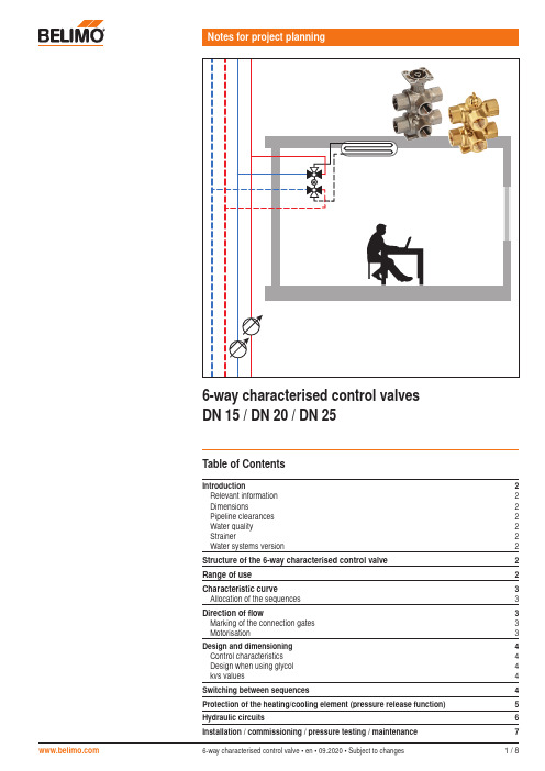
6-way characterised control valve • en • 09.2020 • Subject to changes1 / 8Table of ContentsIntroduction2Relevant information 2Dimensions2Pipeline clearances 2Water quality 2Strainer2Water systems version2Structure of the 6-way characterised control valve 2Range of use 2Characteristic curve 3Allocation of the sequences 3Direction of flow3Marking of the connection gates 3 Motorisation3Design and dimensioning 4Control characteristics 4Design when using glycol 4kvs values4Switching between sequences4Protection of the heating/cooling element (pressure release function) 5Hydraulic circuits6Installation / commissioning / pressure testing / maintenance72 / 86-way characterised control valve • en • 09.2020 • Subject to changes Structure of the 6-way characterised control valve456789231101112136-way characterised control valvesIntroductionRelevant informationThe data, information and limit values listed on the data sheet of the 6-way characterised control valve are to be taken into account and/or complied with, respectively.DimensionsThe dimension of the valve-actuator combination used is dependent not only on the nominal diameter of the valve but also on the actuator used. The dimensions are listed in the R30..-..-..-B.. data sheet.Pipeline clearancesThe minimum clearances between the pipelines and the walls and ceilings required for project planning depend not only on the valve dimensions but also on the selected actuator. The dimensions can be found on the R30..-..-..-B.. data sheet.Water qualityThe water quality requirements specified in VDI 2035 must be adhered to.Strainer6-way characterised control valves are regulating devices. The use of central strainers in the system is recommended in order to prolong their service life for performing control tasks.Water systems versionApplication is permissible only in closed water circuits.1 Connection flange2 Spindle3 Stem packing O-ring (EPDM)4 Closing element 1 with L-bore5 Closing element 2 with L-bore6 Valve seat (PTFE, O-ring EPDM)7 Characterised disc8 Supply sequence 1 connection *9 Return sequence 1 connection *10 Supply sequence 2 connection *11 Return sequence 2 connection *12 Supply heating/cooling element connection *13 Return heating/cooling element connection ** Internal thread according to ISO 7-1DN15: Rp ½", DN20: Rp ¾", DN25: Rp 1"Range of useThe 6-way characterised control valve has been specially developed for use with combined heating and cooling elements. A 6-way characterised control valve performs the function of four2-way valves or two 2-way valves and one changeover valve.H C EelementConventional solution with four 2-way valvesConventional solution with two 2-way valves and one changeover valveSolution with a6-way characterised control valveThe 6-way characterised control valve handles control of hot and cold water.189212111310R30..-..-..-B2/B3R3015-..-..-B1 6-way characterised control valve • en • 09.2020 • Subject to changes3 / 86-way characterised control valvesCharacteristic curveWhen the valve is rotated by 90°, these 3 sequences are run through.kValve tightly closedAllocation of the sequencesAllocation to hot and chilled water is in principle, freely selectable. However, due to installation safety, the definition of an equal allocation for all valves is recommended.!The following mandatory allocation is to be selected when the room temperature controller CRK24-B1 from Belimo is used, due to the control characteristics:Sequence 1 = cooling Sequence 2 = heatingDirection of flowThe direction of flow must be observed.Sequence 1Sequence 2100%Marking of the connection gatesThese are numbered from 1 to 6 for the purpose of secure allocation of the connections during planning and installation.Motorisation6-way characterised control valves are motorised with a rotary actuator. The control must be modulating.R3015-..-..-B1R30..-..-..-B2/B34 / 86-way characterised control valve • en • 09.2020 • Subject to changes 6-way characterised control valvesDesign and dimensioningControl characteristicsTo ensure a valve attains good control characteristics thus a long service life for the control element, it needs to be correctly designed with the correct valve authority.The valve authority av is the benchmark for the control characteristics of the valve in combination with the hydraulic network. The valve authority is the relation between the differential pressure of the fully open valve at nominal flow and the maximum differential pressure for the closed valve. The higher the valve authority, the better the control characteristics. The smaller the valve authority av becomes, the more the operational behaviour of the valve will deviate from the linearity i.e.. the poorer the volumetric flow control will be. In practice the intended av is >0.5.Design when using glycolTo reduce the freezing point of water, salt was added to the water in the past. These werecalled brine applications. Today glycol is used and we talk about cold agents. Depending on the concentration of the cold agent used (type of glycol) and the medium temperature, the density of the water/glycol mixture varies between 1 and 9 percent. The resultant volume deviation is less than the permissible volume tolerance of the valve's k vs value (by ±10 percent according to VDE 2178) and as a rule need not be taken into account even if glycol requires a slightly higher k v value.Depending on the type of glycol, compatibility with the valve materials used must be guaranteed and the permissible maximum concentration (50 percent) must not be exceeded.k vs valuesSince different k vs values are often required for heating and cooling, 6-way characterised control valves are available with different k vs values for sequences 1 and 2. For a full overview, see data sheet R30..-..-..-B.. .Using an additional flow limiterWhen using additional flow limiting valves (e.g. PIQCV C2..QP(T)-.. with manual flow rate setting) or an additional pressure-independent control valve (e.g. motorised PIQCV) atthe system level, it is not necessary to use the flow characterised disc in the 6-way valve in the system to reduce the k vs value. The differential pressure required for operation is kept as low as possible in this manner. In addition, possible noise generation in conjunction with the additional components used is avoided.DN15 max. k vs 0.63 m 3/h: DN15 max. k vs 1.8 m 3/h: DN20 max. k vs 4 m 3/h: DN25 max. k vs 6.3 m 3/h:R3015-P63-P63-B1 R3015-1P8-1P8-B2 R3020-4-4-B2 R3025-6P3-6P3-B3Switching between sequencesAs with all combined heating/cooling elements in 4-pipe systems, mass displacement can occur when using 6-way characterised control valves.Mass displacementWith each switch (from cooling to heating operation or from heating to cooling operation) water is displaced from one circuit to the other. Due to the different medium temperatures, the density of this water differs. Due to the constant volume in the heating/cooling element, the quantity of water displaced has a different mass. When switching from cooling to heating, more mass is shifted then when switching from heating to cooling. This mass displacement can lead to the cooling circuit being emptied.It is important to cater for this normal behaviour. For corresponding recommendations, see the chapter 'Hydraulic circuits'.MediaDue to the mass displacement that occurs, the medium in both circuits needs to have the same properties (glycol concentration). 6-way characterised control valve • en • 09.2020 • Subject to changes 5 / 86-way characterised control valvesProtection of the heating/cooling element (pressure release function)In cases of combined heating/cooling elements, the medium is enclosed in the element when they are in closed status (no heating or cooling). The pressure of the enclosed medium can rise or fall due to changes in medium temperature caused by the ambient temperature. The 6-way characterised control valve have an integrated pressure release function for the purpose of compensating for such pressure changes.Design for pressure releaseThe upper ball of the characterised control valve has a groove that forms a link between the 'Supply Sequence 1' (Gate 1) connection point and the heating/cooling element connected at Gate 2 when the valve is closed.Pressure release Groove for pressure releaseFunction means of the connection to the 'Sequence 1' circuit. No further flow of water takes place after the pressure compensation due to the same absolute pressures in Sequence 1, in the heating and cooling element and in the lower closing element, which closes air-bubble tight.Behaviour in hot or cold operationThe pressure relief function has no influence on the hot or cold operation. When operating sequence 1, the function is on the same side as the desired water flow. When operatingsequence 2, the pressure relief function is not active. A direct mixing of water of the sequences of 1 and 2 is not possible duration operation.k αControl sequence 1Position Valve closedControl sequence 21) Positioning signal for closed position:Operating range drive 2…10 V: Y = 6 Volt Operating range drive 0.5…10 V: Y = 5.25 VoltValve leakage rateEach water circuit is channeled through two valve cones (series circuit). As a result of the continued air-bubble tight closing of the lower closing element 2, the valve continues to exhibit Leakage rate A in accordance with EN 12266-1, even for Sequence 1.Equivalent circuit diagramPressure release6 / 86-way characterised control valve • en • 09.2020 • Subject to changes 6-way characterised control valvesHydraulic circuitsFor correct operation, the following planning instructions need to be complied with, among others:MediaThe medium in both circuits needs to have the same quality (glycol concentration).System pressureThe system pressures in the heating and cooling circuit must have the same value.Possible hydraulic circuitsIn a 4-pipe system with heating and cooling circuits, the effect of mass displacement always exists regardless of the valve used (see chapter on mass displacement). To cater for this behaviour and prevent mass displacement, there are various solutions and corresponding precautionary measures.1. Two expansion vessels– 2. One expansion vessel– One expansion vessel for both circuits. Connection point on the suction side of the pumps.– Pumps at the same height.– Connection line between heating circuit return and cooling circuit return.– The same static pressure on the suction side of the pumps.3. Two expansion vessels in a hydraulic coupling system– The same static pressure on the suction side of the pumps.– Pumps at the same height.– The 2-way valve remains closed during operation.– The 2-way valve will open if the pressures p Heating and p Cooling exhibit a certain difference due to the mass displacement.– The system pressures are balanced.– The 2-way valve is closed again after the compensation.6-way characterised control valve • en • 09.2020 • Subject to changes 7 / 86-way characterised control valvesInstallation/Commissioning/Pressure testing/MaintenanceValve positionThe ball position can be discerned by means of the marking on the top of the spindle.Valve delivery conditionThe valves are delivered ex works as shown with the picture below.Delivery condition conforms to valve position 90°/positioning signal 10 V.Delivery with valve installedFor visualisation purposes, the actuator has two green dots.Only valid for R30..-..-..-B2/B3R3015-..-..-B1 cannot be supplied with the actuator installed ex worksPressure testing Due to the built-in pressure release safety function, the following needs to be observed:Pressure testing with connected heating/cooling elementIf the connected consumer circuit is also to be tested, pressure testing can be performed without additional restrictions in valve positions 'Sequence 1 open' (angle of rotation 0°) or 'Sequence 2 open' (angle of rotation 90°).When tested in closed valve position (45°), note that the connected heating/cooling element is likewise pressurised with the pressure in sequence 1.Pressure testing without connected heating/cooling elementIn valve closed position (45°) the sequence 1 test medium flows via gates 1 and 2. Thisbehaviour does not constitute a malfunction since the valve closes both water circuits reliably due to the air-bubble tightness of the second closing element during operation.Possibilities:– Individual testing of water circuits1. Sequence 1 test with valve in 90° positionNote: Prior to switching, sequence 1 needs to be emptied. 2. Sequence 2 test with valve in 0° positionor– Additional isolation of gate 2Maintenance 6-way characterised control valves are maintenance-free.R3015-..-..-B1R30..-..-..-B2/B3All inclusive.Belimo worldwide: SwitzerlandBELIMO Automation AG Swiss SalesBrunnenbachstrasse 1CH-8340 HinwilTel. +41 (0)43 843 62 12Fax +41 (0)43 843 62 66****************www.belimo.ch。
德国rexroth阀Z2FS6外形尺寸与说明
6011431857 SID-UV1ZB 6111431022 SID-UV1ZC 6012431877 SID-UV1ZBB 6011431869 SID-UV1ZP-RASTA 6112431050 SID-UV1ZP-RASTA 6012431883 SID-UV1ZP-RASTB 1015300205 STANDFUSSDREHBARRAL9006P 1016786000 STANDFUSSEINFACHA 6301106065 T-06N/SC 6301262039 T-62N/SB 6301167054 T-67N/SB 6301268028 T-68NC 6402169038 T-69N(KA)/SB 6301269031 T-69N/SC 6116469043 TI2-A1ZKSB 6116469068 TI2-A1ZKSP 产品描述 Z2FS 型阀门采用夹层板设计,是一种双节流止回阀。它用于一个或两个执行器端口的主流量或先导流量 限制。 两个彼此对称对齐的节流止回阀在一个方向上流动并允许在相反方向上的自由回流。 在供应节流的情况下,液压流体通过通道 A6 经由阀座(2)和节流阀芯(3)形成的节流点(1)引导至致 动器 A6。节流阀芯(3)可以通过固定螺丝(4)轴向调节,以调节节流点(1)。 来自致动器 A?的液压流体返回流动使阀座(2)在节流阀芯(3)的方向上抵靠弹簧(5)移动,并且使得 无阻碍的流动作为止回阀。根据安装位置,可能在供应或排放中发生节流效应。 主流限制(版本“2Q”)
(二)施工作业
安装施工必须小心,切忌撞击脆性材料制作的阀门。
安装前,应将阀门作一检查,核对规格型号,鉴定有无损坏,尤其对于阀杆。还要转动几下,看是否歪斜, 因为运输过程中,最易撞歪阀杆。还要清除阀内的杂物。
液压与气动技术实训指导书-图文
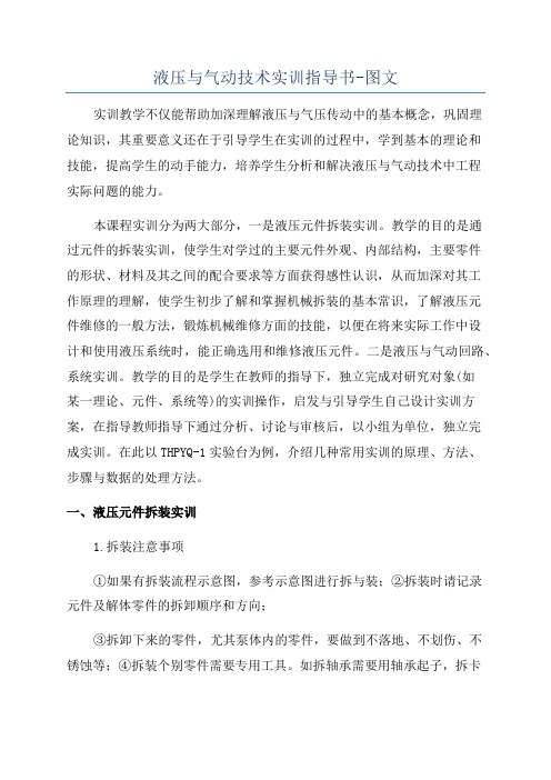
液压与气动技术实训指导书-图文实训教学不仅能帮助加深理解液压与气压传动中的基本概念,巩固理论知识,其重要意义还在于引导学生在实训的过程中,学到基本的理论和技能,提高学生的动手能力,培养学生分析和解决液压与气动技术中工程实际问题的能力。
本课程实训分为两大部分,一是液压元件拆装实训。
教学的目的是通过元件的拆装实训,使学生对学过的主要元件外观、内部结构,主要零件的形状、材料及其之间的配合要求等方面获得感性认识,从而加深对其工作原理的理解,使学生初步了解和掌握机械拆装的基本常识,了解液压元件维修的一般方法,锻炼机械维修方面的技能,以便在将来实际工作中设计和使用液压系统时,能正确选用和维修液压元件。
二是液压与气动回路、系统实训。
教学的目的是学生在教师的指导下,独立完成对研究对象(如某一理论、元件、系统等)的实训操作,启发与引导学生自己设计实训方案,在指导教师指导下通过分析、讨论与审核后,以小组为单位,独立完成实训。
在此以THPYQ-1实验台为例,介绍几种常用实训的原理、方法、步骤与数据的处理方法。
一、液压元件拆装实训1.拆装注意事项①如果有拆装流程示意图,参考示意图进行拆与装;②拆装时请记录元件及解体零件的拆卸顺序和方向;③拆卸下来的零件,尤其泵体内的零件,要做到不落地、不划伤、不锈蚀等;④拆装个别零件需要专用工具。
如拆轴承需要用轴承起子,拆卡环需要用内卡钳等;⑤在需要敲打某一零件时,请用铜棒,切忌用铁或钢棒;⑥拆卸(或安装)一组螺钉时,用力要均匀;⑦安装前要给元件去毛刺,用煤油清洗然后晾干,切忌用棉纱擦干;⑧检查密封有无老化现象,如果有,请更换新的;⑨安装时不要将零件装反,注意零件的安装位置。
有些零件有定位槽孔,一定要对准;⑩安装完毕,检查现场有无漏装元件。
2.实训用工具及材料钳工台虎钳、内六角扳手、活口扳手、螺丝刀、涨圈钳、游标卡尺、钢板尺、润滑油、化纤布料、各类液压泵、液压阀及其它液压元件等。
(一)液压泵拆装实训1.实训目的通过对各种液压泵进行拆装,使学生对各种液压泵的结构有深入了解,并能依据流体力学的基本概念和定律来分析总结容积式泵的特性,掌握各种液压泵的工作原理、结构特点、使用性能等。
力士乐节流阀

DBDS6G1X/50K14 溢流阀,
DBDS10G1X/100 溢流阀,
DBDS10G1X/20 溢流阀,
HED80A1X/50K14 压力继电器
PV7-1X/63-71REO7MCO-14A1 泵
DR10-5-52/20YM 溢流阀,
DR6DP2-5X/75YM 溢流阀,
DGMX2-3-PA-CW-B-40 溢流阀,
DGMPC-7-ABK-BAK-11 液控单向阀,
DG4V-3S-2N-M-U-H5-60 电磁阀,
DGMC-5-PT-FW-B-30 溢流阀,
DGMX2-5-PP-FW-B-30 溢流阀,
DBW10B-1- 安全阀,
4WE6J-L10/AG24NS- 电磁阀,
4WEH16B7X/6EG24N9ETK4+2XZ4 电磁换向阀,
DB10-3-52-/315 溢流阀,
M-3SEW6C35/420MG24N9K4 电磁球阀,
ZDR10VP5-3X/200YMV 减压阀,
M4SC-055-3NOO-A502 液压马达(小)
M4SD-113-3NOO-B502 液压马达(大)
DB20-2-52/200 溢流阀,
DBW30-B2-52/3506EG24N9K4/12 电磁溢流阀,
DBW20B2-52/315S6EG24N9K4R12 电磁溢流阀,
DBW30-B2-52/200S6EG24N9K4R12 电磁溢流阀,
S20A1.0 单向阀,
4WRTE16W6-200L-41/6EG24EK31/F1M 主比例阀,
Z2FS6-4X/S2 双单向节流阀,
YUKEN油研、REXROTH力士乐、VICKERS威格士产品型号对照表
DSHG-04-3C9 4WEH16M51 DG5V-7-7C
DSHG-04-3C10 4WEH16U51 DG5V-7-31C
DSHG-04-3C12 4WEH16L51 DG5V-7-3C
DSHG-04-2B2 4WEH16D51 DG5V-7-2A
DSG-01-3C10 4WE6U51 DG4V-3-31C
DSG-01-3C12 4WE6L51 DG4V-3-3C
DSG-01-2B2 4WE6D51 DG4V-3-2A
DSG-01-2B3 4WE6C51 DG4V-3-OA
MCP-01 Z1S6T DGMDC-3-TX
MCP-03 Z1S10P (DGMDC-5-PY)
MCA-03 Z1S10A
MCB-03 Z1S10B
MCT-03 Z1S10T DGMDC-5-TX
MSW-03-Y Z2FS10 DGMFN-5-X-A-B
常规元件:
溢流阀:(安装面符合ISO-6264-AR,AS,AT)
BG-03 DB10 CG2V-6
BG-06 DB20 CG2V-8
BG-10 DB30 ECG-10
BSG-03 DBW10 CG2V-6
BSG-06 DBW20 CG5V-8
DSG-03-2B8 4WE10A21 DG4V-5-22A
DSG-03-2B2-L 4WE10Y21 DG4V-5-2A-LH
DSG-031-2B3-L DG4V-5-OA-LH
DSG-03-2B8-L 4WE10B21 DG4V-5-22A-LH
DSG-03-2D2 4WE10D/OF DG4V-5-2N
力士乐挖掘机油路介绍
力士乐挖掘机油路介绍黄宗益李兴华目前液压挖掘机有两种油路:开中心直通回油六通阀系统和闭中心负载敏感压力补偿系统,我国国产液压挖掘机大多采用“开中心”系统,而国外著名的挖掘机厂家基本上都采用“闭中心”系统。
闭中心具有明显的优点,目前价格较贵。
国内厂家对开中心系统比较熟悉,而对闭中心系统不太了解,因此有必要来介绍一下闭中心系统,下面介绍力士乐闭中心负载敏感压力补偿(LUDV)挖掘机油路。
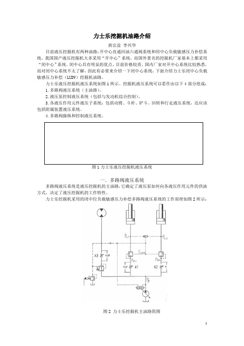
力士乐液压挖掘机液压系统如图1所示。
挖掘机液压系统可以看作由以下4部分组成:1.多路阀液压系统(主油路)。
2.液压泵控制液压系统(包括与发动机综合控制)。
3.各液压作用元件液压子系统:包括动臂、斗杆、铲斗。
回转和行走液压系统,还应该包括附属装置液压系统。
4.多路阀操纵和控制液压系统。
图1力士乐液压挖掘机液压系统一.多路阀液压系统多路阀液压系统是液压挖掘机的主油路,它确定了液压泵如何向各液压作用元件的供油方式,决定了液压挖掘机的工作特性。
力士乐挖掘机采用的闭中位负载敏感压力补偿多路阀液压系统的工作原理如图2所示:图2 力士乐挖掘机主油路简图力士乐挖掘机主油路由二个负载敏感压力补偿系统组成:工装油路和回转油路(一)工作装置和行走油路(除回转外):简称工装油路,采用阀后补偿分流比负载敏感压力补偿系统(LUDV 系统),具有抗饱和功能。
(b ) (c )图3 力士乐多路阀原理符号图LUDV 每个阀块主要由操纵阀和压力补偿阀组成,其原理符号如图3(a )所示,为了看清理解阀的原理,把操纵阀进行分解后可知,它实际上是两部分组成:阀的节流部分和阀的换向部分。
阀块原理展开图如图3(b )所示,压力油进入操纵阀先通过阀节流部分,后经压力补偿阀,最后通过阀换向部分去液压作用元件。
阀后补偿压力补偿阀布置在操纵阀可变节流口之后,由于液压作用元件一般都是双作用,有A 、B 两条油路,为了避免两条油路都设压力补偿阀,因此油路换向部分,必须设在压力补偿阀之后。
bosch rexroth 6 2 路液压阀 技术手册说明书
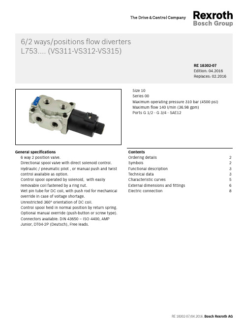
RE 18302-07/04.2016, Bosch Rexroth AGGeneral specifi cations 6 way 2 position valve.Directional spool valve with direct solenoid control. Hydraulic / pneumatic pilot , or manual push and twist control available as option.Control spool operated by solenoid, with easily removable coil fastened by a ring nut.Wet pin tube for DC coil, with push rod for mechanical override in case of voltage shortage. Unrestricted 360° orientation of DC coil.Control spool held in normal position by return spring. Optional manual override (push-button or screw type). Connectors available: DIN 43650 – ISO 4400, AMP Junior, DT04-2P (Deutsch), Free leads.Size 10 Series 00Maximum operating pressure 310 bar (4500 psi) Maximum fl ow 140 l/min (36.98 gpm) Ports G 1/2 - G 3/4 - SAE126/2 ways/positions fl ow diverters L 753.... (VS311-VS312-VS315)RE 18302-07Edition: 04.2016Replaces: 02.2016Contents Ordering details 2Symbols 2Functional description 3Technical data 3Characteristic curves5External dimensions and fi ttings 6Electric connection82L753.... (VS311-VS312-VS315) | 6/2 ways/positions fl ow diverters Ordering detailsOrdering details0102030405060708L7530Family01Compact directional valve LType02Flow diverters7Ports03G 1/2 DIN 38524G 3/4 DIN 385251 1/16-12 UN (SAE12)EControl type04Solenoid (coil C 65) without manual override14Solenoid (coil C 65) with push-button type manualoverride4PSolenoid (coil C65) with screw type manual overridezinc plated screw4FSolenoid (coil C65) with screw type manual overridewith stainless steel screw4X Hydraulic / pneumatic control 1)P1 Manual push and twist control H1Spool variants05 6 way / 2 position P1 side6_ Drain type 6A6B6E6F6G06Internal drain●●–●●IExternal drain●●●––E Voltage supply310703010007Without coil––––●0012 V DC●●●●–OB13 V DC–●–●–AD24 V DC●●●●–OC27 V DC–●–●–AC48 V DC–––●–OD Electric connections08Without coils00With coils, without mating connectorDIN EN 175301-803 2)01 With coils, with bi-directional diode, without matingconnector vertical Amp-Junior03 With coils, with bi-directional diode, without matingconnector DT04-2P07 With coils and bipolar sheathed lead350mm (13,8 in) long31●=Available–=Not available SymbolsDrain type IaC1 C41 0C2C3Drain type EaC1 C41 0C2C3S pool variants6B6E6A6G6F1) Minimum pressure 4 bar (58psi) with external drain (E), maximumpressure 200 bar (2901psi). With internal drain (I), at the minimum pressure (4 bar - 58psi), add the working pressure with ratio of 11:1. Example: With working pressure 100 bar (1450psi), minimum pilot pressure is 13.09 bar (190psi) ((100:11) + 4 bar (58psi)).2) For connectors ordering code see data sheet RE 18325-90.Bosch Rexroth AG, RE 18302-07/04.20166/2 ways/positions fl ow diverters| L753.... (VS311-VS312-VS315)Functional description3Functional descriptionA valve basically consists of a housing (1), a control spool(2), a return spring (3) and a solenoid (5). It is designed to connect two inlet lines P1 – P2 (normally a set of hoses) and divert them to either the outlet ports (C1 – C4) with spool in position “0”, when the solenoid is de-energized, or to the outlet ports (C2 – C3) with spool in position “1”, when the solenoid is energized.With the coil de-energized, the return spring (3) pushes back the spool (2) and holds it in position “0”.The coil (5) is fastened to the tube by the ring nut (6).The manual override (6) allows to shift the spool (2) also in case of voltage shortage.An external drain, to be connected to tank, ensures shifting operations also at higher working pressure.Hydraulic / pneumatic pilot control for spool shifting is available upon request.Technical dataMaximum pressure with external drain (“E” type)bar (psi)310 (4500)Maximum pressure with internal drain (“I” type)bar (psi)250 (3625)Maximum pressure with internal drain and6F or 6G schemebar (psi)310 (4500)Maximum fl ow l/min (gpm)140 (36.98)Pilot pressure needed for hydraulic / pneumatic control bar (psi)max 200 (2900) - min 4 (58) with external drain.For versions with internal drain, the pilot pressure required shouldbe at least 11 times higher than inlet pressure (ratio 11:1).Hydraulic fl uidGeneral properties: it must have physical lubricating and chemical properties suitable for use in hydraulic systems such as, for example:Mineral oil based hydraulic fl uids HL (DIN 51524 part 1). Mineral oil based hydraulic fl uids HLP (DIN 51524 part 2). For use of environmentally acceptable fl uids (vegetable or polyglycol base) please consult us.Fluid Temperature°C (°F)–20....+80 (-4....+176) (NBR seals)Permissible degree of fl uid contamination ISO 4572: βx ≥ 75 X = 12 (15)ISO 4406: class 20/18/15NAS 1638: class 9Viscosity range mm2/s 5 (420)Internal leakage with 100 bar (1450 psi) secondary pressure at C cc/min(in3/min)min. 15 (0.9) - max. 40 (2.4)RE 18302-07/04.2016, Bosch Rexroth AG4L753.... (VS311-VS312-VS315) | 6/2 ways/positions fl ow divertersTechnical dataVoltage type DCVoltage tolerance (nominal voltage)%-10 .... +10Duty Continuous, with ambient temperature ≤ 50°C (122°F)Coil wire temperature not to be exceeded°C (°F)150 (302)Insulation class HCompliance with Low Voltage Directive LVD 73/23/EC (2006/95/EC), 2004/108/EC Coil weight with DIN 43650 – ISO 4400 connector kg (lbs) 1.05 (2.3)Voltage V1213242748Voltage type DC DC DC DC DCPower consumption W4444444444Current (nominal at 20 °C (68 °F))A 3.6 3.4 1.8 1.60.9Resistance (nominal at 20 °C (68 °F))Ω 3.2 3.612.816.950.5NoteFor applications with different specifications consult usBosch Rexroth AG, RE 18302-07/04.2016RE 18302-07/04.2016, Bosch Rexroth AG6/2 ways/positions fl ow diverters | L753.... (VS311-VS312-VS315) Characteristic curves5Characteristic curves2 10 20 40 60 80 100 120 140 l/min bar 8765432100 5 10 15 20 25 30 35 37 gpmpsi 1151007550250P r e s s u r e ΔpFlowQDI-DE performance limits0 20 40 60 80 100 120 140 min0 5 10 15 20 25 30 35 37 gpmFlow QVS3111VS312-VS3152Flow across both ways: forward across P1>C1 and reverse across C4>P2Dimensions [mm (inches)] 6L753.... (VS311-VS312-VS315) | 6/2 ways/positions fl ow divertersExternal dimensions and fi ttingsttingsExternal dimensions and fi1 Ports P1, P2, C1, C2, C3, C4.2 The mounting surface fl atness must comply with specifi cations.3 Two through holes reccomended screws M8x45 with strengthclass DIN 8.8.Torque 15 – 16 Nm (11.1–11.8 ft-lb).4 Ring nut for coil locking Ø 34 mm (1.34 inch).Torque 7–8 Nm (5.2 – 5.9 ft-lb ).5 Solenoid tube Ø 25,4 mm (1.00 inch).6 Minimum clearance needed for connector removal.Bosch Rexroth AG, RE 18302-07/04.2016Dimensions [mm (inches)]76/2 ways/positions fl ow diverters| L753.... (VS311-VS312-VS315)External dimensions and fi ttings7 External drain plug available with G 1/4 and SAE 4 port.8 Identifi cation label.9 Optional push-button, 4P type, manual override for spool opening:it is pressure stuck to the ring nut for coil locking.Mat no. R93300342410 Optional screw type manual override, 4F or 4X types, for spoolopening: it is screwed (torque 8-9 Nm (5.9-6.6 ft-lb)) to the tubeas replacement of the coil ring nut. Mat no. R933003713 zincplated, Mat no. R933009577 stainless steel.11 Dimensions of manual version, push and twist type.12 Dimensions of hydraulic / pneumatic piloted version. Pilot portplug available with G 1/4.RE 18302-07/04.2016, Bosch Rexroth AG8Bosch Rexroth AG , RE 18302-07/04.2016L753.... (VS311-VS312-VS315) | 6/2 ways/positions fl ow diverters Electric connectionBosch Rexroth Oil Control S.p.A.Oleodinamica LC Division Via Artigianale Sedrio, 1242030 Vezzano sul Crostolo Reggio Emilia - Italy Tel. +39 0522 601 801Fax +39 0522 606 226 / 601 802***************************************/compacthydraulics© This document, as well as the data, specifi cations and other information set forth in it, are the exclusive property of Bosch Rexroth Oil Control S.p.a.. It may not be reproduced or given to third parties without its consent.The data specifi ed above only serve to describe the product. No statements concerning a certain condition or suitability for a certain application can be derived from our information. The information given does not release the user from the obligation of own judgment and verifi cation. It must beremembered that our products are subject to a natural process of wear and aging.Subject to change.Dimensions [mm (inches)]E lectric connection。