火炬电子贴片电容命名
贴片电容命

创作编号:GB8878185555334563BT9125XW创作者:凤呜大王*贴片电容命名规则及方法贴片电容的命名:贴片电容的命名所包含的参数有贴片电容的尺寸、做这种贴片电容用的材质、要求达到的精度、要求的电压、要求的容量、端头的要求以及包装的要求例风华系列的贴片电容的命名贴片电容的命名:贴片电容的命名所包含的参数有贴片电容的尺寸、做这种贴片电容用的材质、要求达到的精度、要求的电压、要求的容量、端头的要求以及包装的要求。
一般订购贴片电容需提供的参数要有尺寸的大小、要求的精度、电压的要求、容量值、以及要求的品牌即可。
例风华系列的贴片电容的命名:0805CG102J500NT0805:是指该贴片电容的尺寸套小,是用英寸来表示的08 表示长度是0.08 英寸、05 表示宽度为0.05 英寸CG :是表示做这种电容要求用的材质,这个材质一般适合于做小于10000PF 以下的电容,102 :是指电容容量,前面两位是有效数字、后面的2 表示有多少个零102=10×102 也就是=1000PFJ :是要求电容的容量值达到的误差精度为5%,介质材料和误差精度是配对的500 :是要求电容承受的耐压为50V 同样500 前面两位是有效数字,后面是指有多少个零。
N :是指端头材料,现在一般的端头都是指三层电极(银/铜层)、镍、锡T :是指包装方式,T 表示编带包装,B 表示塑料盒散包装贴片电容的颜色,常规见得多的就是比纸板箱浅一点的黄,和青灰色,这在具体的生产过程中会有产生不同差异贴片电容上面没有印字,这是和他的制作工艺有关(贴片电容是经过高温烧结面成,所以没办法在它的表面印字),而贴片电阻是丝印而成(可以印刷标记)。
贴片电容有中高压贴片电容得普通贴片电容,系列电压有6.3V、10V、16V、25V、50V、100V、200V、500V、1000V、2000V、3000V、4000V贴片电容的尺寸表示法有两种,一种是英寸为单位来表示,一种是以毫米为单位来表示,贴片电容系列的型号有0201、0402、0603、0805、1206、1210、1812、2010、2225 等。
认识贴片电容
认识贴片电容认识贴片电容电容的容量单位为:法(F)、微法(uf),皮法(pf)。
一般我们不用法做单位,因为它太大了。
各单位之间的换算关系为:1F=106uf 1uf=106pf1F=103mf=106uf=109nf=1012pf在使用中,还经常见到单位:nf。
1uf=1000nf 1nf=1000pf电容的容量标识的几种方法:如果标值104,容量就是:10X10000pf=0.1uf。
如果标值473,即为47X1000pf=0.047uf。
(后面的4、3,都表示10的多少次方)。
又如:332=33X100pf=3300pf。
一、电容的贴片式有何好处?节省空间,便于高集成电路设计可靠性、精度变高了,抗干扰能力增强更加安全,无脚刺二、贴片电容的作用是什么?其作用主要是清除由芯片自身产生的各种高频信号对其他芯片的串扰,从而让各个芯片模块能够不受干扰的正常工作。
在高频电子振荡线路中,贴片式电容与晶体振荡器等元件一起组成振荡电路,给各种电路提供所需的时钟频率。
贴片式电容有贴片式陶瓷电容、贴片式钽电容、贴片式铝电解电容。
贴片式陶瓷电容无极性,容量也很小(PF级),一般可以耐很高的温度和电压,常用于高频滤波。
陶瓷电容看起来有点像贴片电阻(因此有时候我们也称之为“贴片电容”),但贴片电容上没有代表容量大小的数字。
贴片式钽电容的特点是寿命长、耐高温、准确度高、滤高频改波性能极好,不过容量较小、价格也比铝电容贵,而且耐电压及电流能力相对较弱。
它被应用于小容量的低频滤波电路中。
贴片钽电容与陶瓷电容相比,其表面均有电容容量和耐压标识,其表面颜色通常有黄色和黑色两种。
譬如100-16即表示容量100μF,耐压16V。
贴片式铝电解电容拥有比贴片式钽电容更大的容量,其多见于显卡上,容量在300μF~1500μF之间,其主要是满足电流低频的滤波和稳压作用。
三、直插电容与贴片电容的区别无论是插件还是贴片式的安装工艺,电容本身都是直立于PCB的,根本的区别方式是贴片工艺安装的电容,有黑色的橡胶底座。
贴片电容选择与命名

Cat.No.C03E-4• This PDF catalog is downloaded from the website of Murata Manufacturing co., ltd. Therefore, it’s specifications are subject to change or our products in it may be discontinued without advance notice. Please check with oursales representatives or product engineers before ordering.• This PDF catalog has only typical specifications because there is no space for detailed specifications. Therefore, please approve our product specifications or transact the approval sheet for product specifications before ordering.!Note C03E.pdf 10.5.20for EU RoHS Compliant• All the products in this catalog comply with EU RoHS.• EU RoHS is "the European Directive 2002/95/EC on the Restriction of the Use of Certain Hazardous Substances in Electrical and Electronic Equipment".• For more details, please refer to our website 'Murata's Approach for EU RoHS' (/info/rohs.html).123245681014192223273334353839414546505153612351s Features1. The GCM series meet AEC-Q200 requirements.2. Higher resistance of solder-leaching due to the Ni-barriered termination, applicable for reflow-soldering, and flow-soldering (GCM18/21/31 type only).3. The operating temperature range of R7/C7/5C series: -55 to 125 degree C.4. A wide selection of sizes is available, from miniature LxWxT:0.6x0.3x0.3mm to LxWxT: 3.2x2.5x2.5mm.5. The GCM series is available in paper or embossed tape and reel packaging for automatic placement.6. The GCM series is lead free product.s ApplicationsAutomotive electronic equipment (Power-train, safety equipment)The figure indicates typical specification.4The part numbering code is shown in ( ) and Unit is shown in [ ]. < >: EIA [inch] Code61The part numbering code is shown in ( ) and Unit is shown in [ ]. < >: EIA [inch] Code71581Temperature Compensating TypeThe part numbering code is shown in ( ) and Unit is shown in [ ]. < >: EIA [inch] CodePackaging Code in Part Number is a code shows STD 180mm Reel Taping.q Product ID w Series e Dimension (L g W)r Dimension (T)t Temperature Characteristics y Rated Voltageu Capacitance i Capacitance Tolerance o Individual Specification Code !0P ackage(Part Number)wGCqM e03r 3t5C y1Eu1R0iC oD03!0D1Temperature Compensating Type1High Dielectric Constant TypeThe part numbering code is shown in ( ) and Unit is shown in [ ]. < >: EIA [inch] CodePackaging Code in Part Number is a code shows STD 180mm Reel Taping.q Product ID w Series e Dimension (L g W)r Dimension (T)t Temperature Characteristics y Rated Voltageu Capacitance i Capacitance Tolerance o Individual Specification Code !0P ackage(Part Number)wGCqM e03r 3tR7y1Eu101iK oA03!0D1High Dielectric Constant TypeThe part numbering code is shown in ( ) and Unit is shown in [ ]. < >: EIA [inch] Code1High Dielectric Constant TypeThe part numbering code is shown in ( ) and Unit is shown in [ ]. < >: EIA [inch] CodePackaging Code in Part Number is a code shows STD 180mm Reel Taping.q Product ID w Series e Dimension (L g W)r Dimension (T)t Temperature Characteristics y Rated Voltageu Capacitance i Capacitance Tolerance o Individual Specification Code !0P ackage(Part Number)wGCqM e21r 6tR7y2Au682iK oA37!0D1High Dielectric Constant TypeThe part numbering code is shown in ( ) and Unit is shown in [ ]. < >: EIA [inch] CodeContinued on the following page.*1: The figure indicates typical specification. Please refer to individual specifications.1Continued on the following page.*1: The figure indicates typical specification. Please refer to individual specifications.*2: Some of the parts are applicable in rated voltage x 150%. Please refer to individual specifications.Continued on the following page.*1: The figure indicates typical specification. Please refer to individual specifications.Continued on the following page.*1: The figure indicates typical specification. Please refer to individual specifications.*1: The figure indicates typical specification. Please refer to individual specifications.Note 1: Nominal values denote the temperature coefficient within a range of 25°C to 125°C (for 5C).11) There are parts number without bulk case.Tape Carrier Packaging1. Dimensions of Reel2. Dimensions of Paper Tape3. Dimensions of Embossed Tape4. Taping Method(1)Tapes for capacitors are wound clockwise. Thesprocket holes are to the right as the tape is pulledtoward the user.(2)Part of the leader and part of the empty tape shouldbe attached to the end of the tape as follows.(3)The top tape and base tape are not attached at theend of the tape for a minimum of 5 pitches.(4)Missing capacitors number within 0.1% of the numberper reel or 1 pc, whichever is greater, and are notcontinuous.(5)The top tape and bottom tape should not protrudebeyond the edges of the tape and should not coversprocket holes.(6)Cumulative tolerance of sprocket holes, 10 pitches:±0.3mm.(7)Peeling off force: 0.1 to 0.6N* in the direction shownbelow.*GCM03: 0.05 to 0.5NDimensions of Bulk Case PackagingThe bulk case uses antistatic materials. Please contact Murata for details.1. The performance of chip monolithic ceramic capacitorsmay be affected by the storage conditions.1-1. Store capacitors in the following conditions:Temperature of +5°C to +40°C and a RelativeHumidity of 20% to 70%.(1) Sunlight, dust, rapid temperature changes,corrosive gas atmosphere or high temperatureand humidity conditions during storage may affectthe solderability and the packaging performance.Please use product within six months of receipt.(2) Please confirm solderability before using aftersix months. Store the capacitors without openingthe original bag. Even if the storage period isshort, do not exceed the specified atmosphericconditions.1-2. Corrosive gas can react with the termination (external) electrodes or lead wires of capacitors, and result in poor solderability. Do not store thecapacitors in an atmosphere consisting of corrosivegas (e.g., hydrogen sulfide, sulfur dioxide, chlorine,ammonia gas, etc.).1-3. Due to moisture condensation caused by rapid humidity changes, or the photochemical changecaused by direct sunlight on the terminal electrodesand/or the resin/epoxy coatings, the solderability and electrical performance may deteriorate. Do not store capacitors under direct sunlight or in high humidityconditions.s Storage and Operation condition 1s Rating1. Temperature Dependent Characteristics2. Measurement of Capacitance1. The electrical characteristics of the capacitor can change with temperature.1-1. For capacitors having larger temperaturedependency, the capacitance may change with temperature changes.The following actions are recommended in order to insure suitable capacitance values.(1) Select a suitable capacitance for the operatingtemperature range.(2) The capacitance may change within the ratedtemperature.When you use a high dielectric constant type capacitors in a circuit that needs a tight (narrow) capacitance tolerance. Example: a time constant circuit., please carefully consider thecharacteristics of these capacitors, such as their aging, voltage, and temperature characteristics. And check capacitors using your actualappliances at the intended environment and operating conditions.1. Measure capacitance with the voltage and the frequency specified in the product specifications.1-1. The output voltage of the measuring equipment maydecrease when capacitance is high occasionally.Please confirm whether a prescribed measured voltage is impressed to the capacitor.1-2. The capacitance values of high dielectric constanttype capacitors change depending on the AC voltage applied. Please consider the AC voltagecharacteristics when selecting a capacitor to be used in a AC circuit.Continued on the following page.-20-15-10-505101520-75-50-25255075100C a p a c i t a n c e C h a n g e (%)Temperature (°C)Typical Temperature Characteristics Char. R6(X5R)C a p a c i t a n c e C h a n g e (%)Temperature (°C)Typical Temperature Characteristics Char. F5(Y5V)Typical Temperature Characteristics Char. R7(X7R)-20-15-10-505101520-75-50-25255075100125150C a p a c i t a n c e C h a n g e (%)Temperature (°C)-100-80-60-40-2002040-50-2525507510013. Applied Voltage4. Applied Voltage and Self-heating Temperature1. Do not apply a voltage to the capacitor that exceeds the rated voltage as called-out in the specifications.1-1. Applied voltage between the terminals of a capacitorshall be less than or equal to the rated voltage.(1) When AC voltage is superimposed on DC voltage,the zero-to-peak voltage shall not exceed the rated DC voltage.When AC voltage or pulse voltage is applied, the peak-to-peak voltage shall not exceed the rated DC voltage.(2) Abnormal voltages (surge voltage, staticelectricity, pulse voltage, etc.) shall not exceed the rated DC voltage.1. When the capacitor is used in a high-frequency voltage, pulse voltage, application, be sure to take into account self-heating may be caused by resistant factors of the capacitor.1-1. The load should be contained to the level such thatwhen measuring at atmospheric temperature of 25°C, the product's self-heating remains below 20°C and surface temperature of the capacitor in the actual circuit remains within the maximum operating temperature.1-2. Influence of overvoltageOvervoltage that is applied to the capacitor may result in an electrical short circuit caused by the breakdown of the internal dielectric layers .The time duration until breakdown depends on the applied voltage and the ambient temperature.Continued on the following page.5. DC Voltage and AC Voltage Characteristic1. The capacitance value of a high dielectric constant type capacitor changes depending on the DC voltage applied.Please consider the DC voltage characteristics when a capacitor is selected for use in a DC circuit.1-1. The capacitance of ceramic capacitors may changesharply depending on the applied voltage. (See figure)Please confirm the following in order to secure the capacitance.(1) Whether the capacitance change caused by theapplied voltage is within the range allowed or not. (2) In the DC voltage characteristics, the rate ofcapacitance change becomes larger as voltage increases. Even if the applied voltage is below the rated voltage. When a high dielectric constant type capacitor is in a circuit that needs a tight (narrow) capacitance tolerance. Example: a time constant circuit., please carefully consider the characteristics of these capacitors, such as their aging, voltage, and temperature characteristics. And check capacitors using your actualappliances at the intended environment and operating conditions.2. The capacitance values of high dielectric constant type capacitors change depending on the AC voltage applied.Please consider the AC voltage characteristics when selecting a capacitor to be used in a AC circuit.-60-50-40-30-20-1001020300.00.51.01.52.02.5AC Voltage (Vr.m.s.)6. Capacitance Aging1. The high dielectric constant type capacitors have the characteristic in which the capacitance value decreases with passage of time.When you use a high dielectric constant type capacitors in a circuit that needs a tight (narrow) capacitance tolerance. Example: a time constant circuit., pleasecarefully consider the characteristics of these capacitors, such as their aging, voltage, and temperaturecharacteristics. And check capacitors using your actual appliances at the intended environment and operating conditions.-100-80-60-40-2002001234567DC Voltage (VDC)[DC Voltage Characteristics][AC Voltage Characteristics]C a p a c i t a n c e C h a n g e (%)C a p a c i t a n c e C h a n g e (%)7. Vibration and Shock1. The capacitors mechanical actress (vibration and shock)shall be specified for the use environment.Please confirm the kind of vibration and/or shock, itscondition, and any generation of resonance.Please mount the capacitor so as not to generateresonance, and do not allow any impact on the terminals.2. Mechanical shock due to falling may cause damage or acrack in the dielectric material of the capacitor.Do not use a fallen capacitor because the quality and reliability may be deteriorated.3. When printed circuit boards are piled up or handled, thecorners of another printed circuit board should not beallowed to hit the capacitor in order to avoid a crack or other damage to the capacitor.s Soldering and Mounting 1. Confirm the best mounting position and direction that minimizes the stress imposed on the capacitor during flexing or bending the printed circuit board.1-1. Choose a mounting position that minimizes thestress imposed on the chip during flexing or bending of the board.1. Mounting Position2. Information before Mounting1. Do not re-use capacitors that were removed from the equipment.2. Confirm capacitance characteristics under actual applied voltage.3. Confirm the mechanical stress under actual process and equipment use.4. Confirm the rated capacitance, rated voltage and other electrical characteristics before assembly.5. Prior to use, confirm the Solderability for the capacitors that were in long-term storage.6. Prior to measuring capacitance, carry out a heattreatment for capacitors that were in long-term storage.7. The use of Sn-Zn based solder will deteriorate the reliability of the MLCC.Please contact our sales representative or productengineers on the use of Sn-Zn based solder in advance.Continued on the following page.3. Maintenance of the Mounting (pick and place) Machine1. Make sure that the following excessive forces are not applied to the capacitors.1-1. In mounting the capacitors on the printed circuitboard, any bending force against them shall be kept to a minimum to prevent them from any bending damage or cracking. Please take into account the following precautions and recommendations for use in your process.(1) Adjust the lowest position of the pickup nozzle soas not to bend the printed circuit board.(2) Adjust the nozzle pressure within a static load of1N to 3N during mounting.2. Dirt particles and dust accumulated between the suction nozzle and the cylinder inner wall prevent the nozzle from moving smoothly. This imposes greater force upon the chip during mounting, causing cracked chips. Also the locating claw, when worn out, imposes uneven forces on the chip when positioning, causing cracked chips. The suction nozzle and the locating claw must be maintained, checked and replaced periodically.14-1. Reflow Soldering1. When sudden heat is applied to the components, the mechanical strength of the components will decrease because a sudden temperature change causesdeformation inside the components. In order to prevent mechanical damage to the components, preheating is required for both the components and the PCB board.Preheating conditions are shown in table 1. It is required to keep the temperature differential between the solder and the components surface (∆T) as small as possible.2. Solderability of Tin plating termination chips might be deteriorated when a low temperature soldering profile where the peak solder temperature is below the melting point of Tin is used. Please confirm the Solderability of Tin plated termination chips before use.3. When components are immersed in solvent after mounting, be sure to maintain the temperature difference (∆T)between the component and the solvent within the range shown in the table 1.Inverting the PCBMake sure not to impose any abnormal mechanical shocks to the PCB.Continued on the following page.Pb-Sn Solder: Sn-37PbLead Free Solder: Sn-3.0Ag-0.5Cu4. Optimum Solder Amount for Reflow Soldering4-1. Overly thick application of solder paste results in aexcessive solder fillet height.This makes the chip more susceptible to mechanical and thermal stress on the board and may cause the chips to crack.4-2. Too little solder paste results in a lack of adhesivestrength on the outer electrode, which may result in chips breaking loose from the PCB.4-3. Make sure the solder has been applied smoothly tothe end surface to a height of 0.2mm* min.5. Optimum Solder Amount for Flow Soldering5-1. The top of the solder fillet should be lower than thethickness of components. If the solder amount is excessive, the risk of cracking is higher during board bending or any other stressful condition.Pb-Sn Solder: Sn-37PbLead Free Solder: Sn-3.0Ag-0.5Cu4-2. Flow Soldering1. When sudden heat is applied to the components, the mechanical strength of the components will decrease because a sudden temperature change causesdeformation inside the components. In order to prevent mechanical damage in the components, preheating should be required for both of the components and the PCB board.Preheating conditions are shown in table 2. It is required to keep temperature differential between the solder and the components surface (∆T) as small as possible.2. Excessively long soldering time or high solderingtemperature can result in leaching of the outer electrodes, causing poor adhesion or a reduction in capacitance value due to loss of contact between electrodes and end termination.3. When components are immersed in solvent aftermounting, be sure to maintain the temperature difference (∆T) between the component and solvent within the range shown in the table 2.4. Do not apply flow soldering to chips not listed in table 2.4-3. Correction with a Soldering Iron1. When sudden heat is applied to the components when using a soldering iron, the mechanical strength of the components will decrease because the extremetemperature change can cause deformations inside the components. In order to prevent mechanical damage to the components, preheating is required for both thecomponents and the PCB board. Preheating conditions, (The "Temperature of the Soldering Iron Tip", "Preheating Temperature", "Temperature Differential" between the iron tip and the components and the PCB), should be within the conditions of table 3. It is required to keep the temperature differential between the soldering iron and the component surfaces (∆T) as small as possible.2. After soldering, do not allow the component/PCB to rapidly cool down.3. The operating time for the re-working should be as short as possible. When re-working time is too long, it may cause solder leaching, and that will cause a reduction in the adhesive strength of the terminations.4. Optimum Solder amount when re-working with a Soldering lron4-1. In case of sizes smaller than 0603, (GCM03/15/18),the top of the solder fillet should be lower than 2/3's of the thickness of the component or 0.5mm whichever is smaller. In case of 0805 and larger sizes, (GCM21/31/32), the top of the solder fillet should be lower than 2/3's of the thickness of the component. If the solder amount is excessive, the risk of cracking is higher during board bending or under any other stressful condition.4-2. A soldering iron with a tip of ø3mm or smaller shouldbe used. It is also necessary to keep the soldering iron from touching the components during the re-work.4-3. Solder wire with ø0.5mm or smaller is required forsoldering.4-4. Leaded Component Insertion1. If the PCB is flexed when leaded components (such as transformers and ICs) are being mounted, chips may crack and solder joints may break.Before mounting leaded components, support the PCB using backup pins or special jigs to prevent warping.5. WashingExcessive ultrasonic oscillation during cleaning can cause the PCBs to resonate, resulting in cracked chips or broken solder joints. Take note not to vibrate PCBs.*Applicable for both Pb-Sn and Lead Free Solder.Pb-Sn Solder: Sn-37PbLead Free Solder: Sn-3.0Ag-0.5CuContinued on the following page.6. Electrical Test on Printed Circuit Board1. Confirm position of the support pin or specific jig, when inspecting the electrical performance of a capacitor after mounting on the printed circuit board.1-1. Avoid bending printed circuit board by the pressureof a test pin, etc.The thrusting force of the test probe can flex the PCB, resulting in cracked chips or open solder joints.Provide support pins on the back side of the PCB to prevent warping or flexing.1-2. Avoid vibration of the board by shock when a test pincontacts a printed circuit board.7. Printed Circuit Board Cropping1. After mounting a capacitor on a printed circuit board, do not apply any stress to the capacitor that is caused by bending or twisting the board.1-1. In cropping the board, the stress as shown right maycause the capacitor to crack.Try not to apply this type of stress to a capacitor.2. Check of the cropping method for the printed circuit board in advance.2-1. Printed circuit board cropping shall be carried out byusing a jig or an apparatus to prevent the mechanical stress which can occur to the board.(1) Example of a suitable jigRecommended example: the board should be pushed as close to the near the cropping jig as possible and from the back side of board in order to minimize the compressive stress applied to capacitor.Not recommended example* when the board is pushed at a point far from the cropping jig and from the front side of board as below, thecapacitor may form a crack caused by the tensile stress applied to capacitor.(2) Example of a suitable machinemachine is shown as follows. Along the lines with the V-grooves on printed circuit board, the topand bottom blades are aligned to one anotherwhen cropping the board.The misalignment of the position between top andbottom blades may cause the capacitor to crack.1. Under Operation of Equipment1-1. Do not touch a capacitor directly with bare hands during operation in order to avoid the danger of aelectric shock.1-2. Do not allow the terminals of a capacitor to come in contact with any conductive objects (short-circuit).Do not expose a capacitor to a conductive liquid,inducing any acid or alkali solutions.1-3. Confirm the environment in which the equipment will operation is under the specified conditions.Do not use the equipment under the followingenvironment.(1) Being spattered with water or oil.(2) Being exposed to direct sunlight.(3) Being exposed to Ozone, ultraviolet rays orradiation.(4) Being exposed to toxic gas (e.g., hydrogen sulfide,sulfur dioxide, chlorine, ammonia gas, etc.)(5) Any vibrations or mechanical shocks exceedingthe specified limits.(6) Moisture condensing environments.1-4. Use damp proof countermeasures if using under any conditions that can cause condensation.2. Others2-1. In an Emergency(1) If the equipment should generate smoke, fire orsmell, immediately turn off or unplug theequipment.If the equipment is not turned off or unplugged,the hazards may be worsened by supplyingcontinuous power.(2) In this type of situation, do not allow face andhands to come in contact with the capacitor orburns may be caused by the capacitors hightemperature.2-2. Disposal of WasteWhen capacitors are disposed, they must be burned or buried by the industrial waste vender with theappropriate licenses.2-3. Circuit DesignGRM, GCM, GMA/D, LLL/A/M, ERB, GQM, GJM,GNM Series capacitors in this catalog are not safety certified products.2-4. RemarksFailure to follow the cautions may result, worst case, in a short circuit and smoking when the product isused.The above notices are for standard applications and conditions. Contact us when the products are used in special mounting conditions.Select optimum conditions for operation as theydetermine the reliability of the product after assembly.The data herein are given in typical values, notguaranteed ratings.s Others11. Operating Temperature1. The operating temperature limit depends on thecapacitor.1-1. Do not apply temperatures exceeding the upper operating temperature.It is necessary to select a capacitor with a suitablerated temperature which will cover the operatingtemperature range.Also it is necessary to consider the temperaturedistribution in equipment and the seasonaltemperature variable factor.1-2. Consider the self-heating of the capacitorThe surface temperature of the capacitor shall bethe upper operating temperature or less whenincluding the self-heating factors.2. Atmosphere Surroundings (gaseous and liquid)1. Restriction on the operating environment of capacitors.1-1. The capacitor, when used in the above, unsuitable, operating environments may deteriorate due tothe corrosion of the terminations and thepenetration of moisture into the capacitor.1-2. The same phenomenon as the above may occur when the electrodes or terminals of the capacitorare subject to moisture condensation.1-3. The deterioration of characteristics and insulation resistance due to the oxidization or corrosion ofterminal electrodes may result in breakdown whenthe capacitor is exposed to corrosive or volatilegases or solvents for long periods of time.3. Piezo-electric Phenomenon1. When using high dielectric constant type capacitors inAC or pulse circuits, the capacitor itself vibrates atspecific frequencies and noise may be generated.Moreover, when the mechanical vibration or shock isadded to capacitor, noise may occur.s Rating 11s Soldering and Mounting1. PCB Design1. Notice for Pattern Forms1-1. Unlike leaded components, chip components aresusceptible to flexing stresses since they aremounted directly on the substrate.They are also more sensitive to mechanical andthermal stresses than leaded components.Excess solder fillet height can multiply these stressesand cause chip cracking. When designing substrates,take land patterns and dimensions into considerationto eliminate the possibility of excess solder filletheight.1-2. It is possible for the chip to crack by the expansionand shrinkage of a metal board. Please contact us ifyou want to use our ceramic capacitors on a metalboard such as Aluminum.(in mm)Continued on the following page.2. Land Dimensions2-1. Chip capacitor can be cracked due to the stress ofPCB bending / etc if the land area is larger than needed and has an excess amount of solder.Please refer to the land dimensions in table 1 for flow soldering, table 2 for reflow soldering.Please confirm the suitable land dimension by evaluating of the actual SET / PCB.2. Adhesive Application1. Thin or insufficient adhesive can cause the chips to loosen or become disconnected during flow soldering.The amount of adhesive must be more than dimension c, shown in the drawing at right, to obtain the correct bonding strength.The chip's electrode thickness and land thickness must also be taken into consideration.2. Low viscosity adhesive can cause chips to slip after mounting. The adhesive must have a viscosity of 5000Pa • s (500ps) min. (at 25°C).*Nominal Value3. Adhesive Curing1. Insufficient curing of the adhesive can cause chips todisconnect during flow soldering and causes deterioration in the insulation resistance between the outer electrodes due to moisture absorption.Control curing temperature and time in order to prevent insufficient hardening.。
[已整理]贴片电容
![[已整理]贴片电容](https://img.taocdn.com/s3/m/0af680efb8f67c1cfad6b820.png)
的电压、要求的容量、端头的要求以及包装的要求。一般订购贴片电容需提供的参数要有尺寸的大小、
要求的精度、电压的要求、容量值、以及要求的品牌即可。
例风华系列的贴片电容的命名:
0805CG102J500NT
0805:是指该贴片电容的尺寸套小,是用英寸来表示的08 表示长度是0.08 英寸、05 表示宽度为
1206 1000pF---0.15μF 1000pF---0.047μF
1210 1000pF---0.22μF 1000pF---0.1μF
2225 0.01μF---1μF 0.01μF---0.56μF
* Z5U电容器
Z5U电容器称为”通用”陶瓷单片电容器。这里首先需要考虑的是使用温度范围,对于Z5U电容器主要的是它的小尺寸和低成本。对于上述三种陶瓷单片电容起来说在相同的体积下Z5U电容器有最大的电容量。但它的电容量受环境和工作条件影响较大,它的老化率最大可达每10年下降5%。尽管它的容量不稳定,由于它具有小体积、等效串联电感(ESL)和等效串联电阻(ESR)低、良好的频率响应,使其具有广泛的应用范围。尤其是在退耦电路的应用中。下表给出了Z5U电容器的取值范围。
500 :是要求电容承受的耐压为50V 同样500 前面两位是有效数字,后面是指有多少个零。
N :是指端头材料,现在一般的端头都是指三层电极(银/铜层)、镍、锡
T :是指包装方式,T 表示编带包装,B 表示塑料盒散包装
贴片电容的颜色,常规见得多的就是比纸板箱浅一点的黄,和青灰色,这在具体的生产过程中会有产
A 3216 10V
B 3528 16V
C 6032 25V
D 7343 35V
贴片电容的尺寸表示法有两种,一种是英寸为单位来表示,一种是以毫米为单位来表示,贴
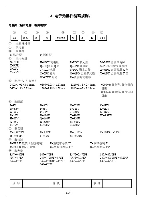
电子元器件命名规则
G=10V
E=16V
H=20V
A=25V
F=35V
B=50V
I=63V
P=75V
D=100V
Q=160V
R=200V
L=250V
O=275V
S=315V
T=350V
Y=400V
X=450V
M=500V
Z=630V
C=1KV
Kபைடு நூலகம்2KV
U=3KV
W=6.3KV
⑧:表误差
C=±0.25PF
D=±0.5PF
L=DIP18
M=DIP20
N=DIP24
O=DIP28
P=DIP40
Q=DIP42
Y=SO-4
V=TO-220
W=TO-92
S=SSOP5-P
X=P-DSO-6
Z=SOT89
⑦:表型号
光电晶体类(受光管、投光管)
①②③④⑤⑥⑦⑧⑨⑩⑾
①:表原材料类
②:表光电晶体类
③:表规格
D=投光管
T=受光电晶体
C=1KV
K=2KV
U=3KV
W=6.3KV
⑦:表误差
C=±0.25PF
D=±0.5PF
F=±1PF
J=±5%
K=±10%
M=±20%
Z=+80%,-20%
⑧:表包装
B=BULK散装(塑胶袋装)
C=BULKCASE盒装
E=塑胶带卷装7"
U=塑胶带卷装13"
T=纸带卷装7"
K=纸带卷装13"
⑨:表容量
如M05,M08,M12,M18,M30,M40,M50,M60,M70等
国巨贴片电容命名规则
国巨贴片电容命名规则国巨是一家知名的电子元件制造商,专注于贴片电容的研发、生产和销售。
贴片电容是一种常见的电子元件,用于电路中的电容器功能。
在国巨的产品线中,贴片电容的命名规则遵循国际电子工程师学会(IEEE)的标准,以下是关于国巨贴片电容命名规则的详细说明。
1.材料型号:这是贴片电容的一种简称,通常是一个字母或几个字母的组合。
国巨的贴片电容产品有多个材料型号,如X7R、X5R、Y5V等。
2.电容值:贴片电容的电容值用来表示其储存电荷的能力。
它通常以皮法(pF)作为单位。
国巨的贴片电容产品的电容值可以从几个皮法到几百微法不等。
3.公差:公差是电容值的测量误差范围。
它用百分比表示。
国巨的贴片电容产品的公差范围通常在几个百分点内。
4.电压额定值:这是贴片电容所能承受的最大电压值。
它通常以伏特(V)作为单位。
国巨的贴片电容产品的电压额定值可以从几十伏特到几百伏特不等。
CC0402GRNPO9BN101在这个示例中,CC表示贴片电容的类型,0402表示它的尺寸,G表示它的公差,R表示它的电压额定值,NPO表示它的材料型号,9BN101表示它的电容值。
贴片电容的尺寸通常采用长宽的编码方式。
以0402为例,它表示贴片电容的尺寸为0.04英寸×0.02英寸。
贴片电容的尺寸越小,它在电路板上占据的空间就越小。
最后,贴片电容的电容值通常是由数字表示的。
例如,在示例中,9BN101表示电容值为100皮法。
总体而言,国巨贴片电容的命名规则遵循了材料、电容值、公差、电压额定值这几个主要参数。
这些参数的组合可以用来唯一地标识每个贴片电容产品,并描述其性能和特点。
了解这些命名规则有助于电子工程师和制造商选择适合其应用需求的贴片电容产品。
贴片电容的种类和特点
贴片电容的种类和特点单片陶瓷电容器(通称贴片电容)是目前用量比较大的常用元件,就A VX公司生产的贴片电容来讲有NPO、X7R、Z5U、Y5V等不同的规格,不同的规格有不同的用途。
下面我们仅就常用的NPO、X7R、Z5U和Y5V来介绍一下它们的性能和应用以及采购中应注意的订货事项以引起大家的注意。
不同的公司对于上述不同性能的电容器可能有不同的命名方法,这里我们引用的是AVX公司的命名方法,其他公司的产品请参照该公司的产品手册。
NPO、X7R、Z5U和Y5V的主要区别是它们的填充介质不同。
在相同的体积下由于填充介质不同所组成的电容器的容量就不同,随之带来的电容器的介质损耗、容量稳定性等也就不同。
所以在使用电容器时应根据电容器在电路中作用不同来选用不同的电容器。
一NPO电容器NPO是一种最常用的具有温度补偿特性的单片陶瓷电容器。
它的填充介质是由铷、钐和一些其它稀有氧化物组成的。
NPO电容器是电容量和介质损耗最稳定的电容器之一。
在温度从-55℃到+125℃时容量变化为0±30ppm/℃,电容量随频率的变化小于±0.3ΔC。
NPO电容的漂移或滞后小于±0.05%,相对大于±2%的薄膜电容来说是可以忽略不计的。
其典型的容量相对使用寿命的变化小于±0.1%。
NPO电容器随封装形式不同其电容量和介质损耗随频率变化的特性也不同,大封装尺寸的要比小封装尺寸的频率特性好。
下表给出了NPO电容器可选取的容量范围。
封装DC=50V DC=100V0805 0.5---1000pF 0.5---820pF1206 0.5---1200pF 0.5---1800pF1210 560---5600pF 560---2700pF2225 1000pF---0.033μF 1000p F---0.018μFNPO电容器适合用于振荡器、谐振器的槽路电容,以及高频电路中的耦合电容。
二X7R电容器X7R电容器被称为温度稳定型的陶瓷电容器。
村田贴片电容命名规则
村田贴片电容命名规则村田贴片电容是电子元件领域中常用的一种电容器。
村田公司作为世界领先的电子元件制造商之一,其产品质量和可靠性备受行业认可。
为了方便区分和标识不同类型的村田贴片电容,村田公司制定了一套严格的命名规则。
1. 村田贴片电容的型号命名规则村田贴片电容的型号一般由数字和字母组成。
其中,数字代表电容器的容量,而字母则代表其他相关参数。
2. 容量值的表示方法容量值是村田贴片电容型号中最重要的部分,通常由3位数字表示。
这三位数字可以分为两部分,例如,数字123可以表示为12和3,即12乘以10的3次方,即12000皮法(pF)。
3. 字母代表其他参数村田贴片电容型号中的字母部分代表其他重要参数。
以下是常见的字母及其代表的参数:- A:温度系数- B:规格系列- C:电压额定值- E:产品尺寸- F:供应形式- G:包装形式- H:寿命- J:包装方式- K:容量偏差- L:引脚排列方式- M:其他特殊规格- N:终端电极材料- P:外壳形状- Q:限制条件- R:电容器类型- T:产品形式- U:终端电极材料厚- X:指示材料类型4. 村田贴片电容型号示例以下是一些常见的村田贴片电容型号及其对应的容量和参数:- GRM188R71C104KA01:容量为100,000皮法,温度系数为±10ppm/℃,额定电压为25V。
- GRM21BR72E473KA01L:容量为47,000皮法,规格系列为BR系列,额定电压为25V,产品尺寸为0805,引脚排列方式为L。
- GRM155R61E105KE11D:容量为1,000,000皮法,额定电压为25V,产品尺寸为0402,引脚排列方式为D,寿命为2,000小时。
通过村田贴片电容的命名规则,用户可以快速准确地找到需要的电容器型号,并确保选用合适的电容器满足自己的需求。
总结:村田贴片电容命名规则包括数字和字母。
数字代表电容器的容量,字母代表其他参数。
风华贴片电容命名规则
风华贴片电容命名规则风华贴片电容,听名字就觉得很高大上,对吧?它在我们生活中可真是个好帮手。
咱们从最基本的开始聊聊,电容器其实就是一个储存电能的小家伙。
说白了,它就像是个电能的储蓄罐,随时准备为电路里的小伙伴们提供能量。
想象一下,如果没有它,电路里可就得苦了,电能一瞬间就没有了,大家都得愁眉苦脸。
而风华贴片电容,哎呀,那可是电容界的明星。
它的外形小巧,像个可爱的小饼干,贴在电路板上,简直就是个精致的装饰品。
可千万别小看它哦,虽然外表不咋地,但它的实力可是一点都不含糊。
风华贴片电容的命名规则,听起来像是个复杂的科学公式,但其实并没有那么神秘。
名字里一般会有几个字母,字母代表不同的特性。
比如说,“C”就代表电容器,“X”可能表示绝缘材料,简单吧?这些字母就像是电容的身份证,告诉你它的身份和能力。
说到这,我总觉得这就像是给每个电容编个小号,让它们在电路中也能有个“自我介绍”,是不是很有趣?风华贴片电容的容量单位,通常是以“μF”为主,别看这个单位看起来像是个外星人语言,其实它代表的是微法拉,简单来说就是储存电能的能力。
容量越大,储存的电能就越多,就像咱们买了个大储蓄罐,存的钱可多着呢。
这样一来,电路在工作时就能更稳定,省得老出问题,真是省心又省力。
再来聊聊电压,风华贴片电容的名字里通常会提到电压等级。
这个就像是电容的安全线,电压超过了,它就有可能“罢工”。
就好比你在夏天开空调,电压太低,空调可能就不转了。
因此,选择适合电压的电容,是非常重要的,搞得不好可就得重新买,真是麻烦得很。
电容的耐温范围也是命名的一部分。
一般说到“高温”或“低温”,这可不是天气预报哦,而是它能在多高或多低的温度下正常工作。
这个就像你冬天穿羽绒服,夏天穿短袖,得看情况啊。
电容耐热的好,才不容易出问题,使用寿命就更长。
想象一下,家里电器工作了多年,突然来个大修,谁都不乐意,还是稳稳当当地使用最划算。
在电路板设计中,风华贴片电容也是个不可或缺的角色。
电子材料参数
第一章贴片电容的精度表示方法一、电容的型号命名:1)各国电容器的型号命名很不统一,国产电容器的命名由四部分组成:第一部分:用字母表示名称,电容器为C。
第二部分:用字母表示材料。
第三部分:用数字表示分类。
第四部分:用数字表示序号。
2)电容的标志方法:(1)直标法:用字母和数字把型号、规格直接标在外壳上。
(2)文字符号法:用数字、文字符号有规律的组合来表示容量。
文字符号表示其电容量的单位:P、N、u、m、F 等。
和电阻的表示方法相同。
标称允许偏差也和电阻的表示方法相同。
小于10pF的电容,其允许偏差用字母代替:B——±0.1pF,C——±0.2pF,D——±0.5pF,F——±1pF。
(3)色标法:和电阻的表示方法相同,单位一般为pF。
小型电解电容器的耐压也有用色标法的,位置靠近正极引出(4)进口电容器的标志方法:进口电容器一般有6项组成。
第一项:用字母表示类别:第二项:用两位数字表示其外形、结构、封装方式、引线开始及与轴的关系。
备注:温度系数的单位10e -6/℃;允许偏差是% 。
第四项:用数字和字母表示耐压,字母代表有效数值,数字代表被乘数的10的幂。
第五项:标称容量,用三位数字表示,前两位为有效数值,第三为是10的幂。
当有小数时,用R或P表示。
普通电容器的单位是pF,电解电容器的单位是uF。
第六项:允许偏差。
用一个字母表示,意义和国产电容器的相同。
也有用色标法的,意义和国产电容器的标志方法相同。
3.电容的主要特性参数:(1)容量与误差:实际电容量和标称电容量允许的最大偏差范围。
一般分为3级:I级±5%,II级±10%,III级±20%。
在有些情况下,还有0级,误差为±20%。
精密电容器的允许误差较小,而电解电容器的误差较大,它们采用不同的误差等级。
常用的电容器其精度等级和电阻器的表示方法相同。
用字母表示:D——005级——±0.5%;F——01级——±1%;G——02级——±2%;J——I级——±5%;K——II级——±10%;M——III级——±20%。