LTE物理层协议
LTE物理层协议分析001_同步过程
L TE 物理层协议分析——同步过程本文主要分析物理层的同步过程,其主要源于协议TS36.213。
一、概述同步过程用于保证UE 与ENB 之间的上行链路的时间和频率的同步。
同步过程主要分为两类场景:一是入网场景下的同步,此时UE 通过PSS 和SSS 完成下行链路的同步,通过PRACH 和TA 命令(RAR 中)完成上行链路链路的同步;二是在网场景下的同步,此时UE 通过PSS 和SSS 信号维护下行链路的同步,通过PRACH 、DMRS/SRS 和TA 命令(RAR 或其他PDSCH 数据中)维护上行链路的同步。
需要特别注意的是,在网场景下若无上行数据传输,允许ENB 和UE 之间的上行链路不同步——即上行同步只在有上行数据传输时才被需要。
二、上行链路同步过程TA (Time Advanced )命令指示了上行所有信道和信号的发送时间提前量,用于支持所有UE 发送的上行信号能够同时到达eNodeB ,以便eNodeB 正确接收上行信号。
eNodeB 通过MAC 层的MCE 或RAR 数据单元将TA 信息以TA Command 的形式发送给UE ,TA Command 表示发送时间提前量的基本单位为16Ts 。
物理层不提供相关控制字段接口。
因此,严格意义来讲,TA 并非无线传输资源,但却决定了UE 发送的上行信号是否能够正确接收。
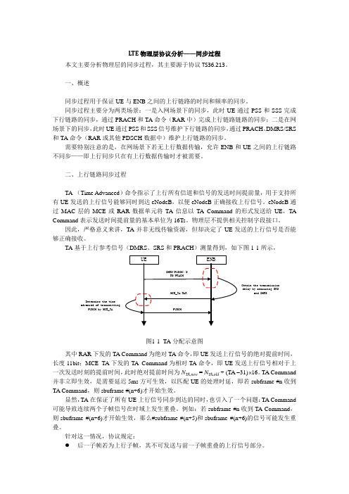
TA 基于上行参考信号(DMRS 、SRS 和PRACH )测量得到,如下图1-1所示, UEENB DMRS(PUSCH)/SRS/PRACHObtain the transmissiondelay by measuring SRSand DMRS MCE_TA/RARPUSCHDetermine the timeadvanced of transmittingPUSCH by MCE_TA图1-1 TA 分配示意图其中RAR 下发的TA Command 为绝对TA 命令,即UE 发送上行信号的绝对提前时间,长度11bit ;MCE_TA 下发的TA Command 为相对TA 命令,即UE 发送上行信号相对于上一次发送时刻的提前时间,此时绝对提前时间为N TA,new = N TA ,old + (TA −31)×16。
lte协议栈
lte协议栈LTE(Long Term Evolution)是第四代移动通信网络(4G)的一种技术标准,其协议栈是指在LTE网络中用于实现通信功能的一系列协议。
LTE协议栈包括物理层、数据链路层、网络层和应用层等组成部分,下面将对LTE协议栈的各个层进行介绍。
物理层是整个协议栈的最底层,主要负责对无线信号的调制解调、信道编码和解码等任务。
其具体功能包括无线信号调制解调、功率控制、调度和调制解调器功耗管理等。
物理层的设计需要考虑带宽、频率复用、多天线技术等因素,以提供高吞吐量和低时延的通信性能。
数据链路层负责将物理层传输的信号分割成较小的数据单元,并提供数据传输的可靠性和安全性保证。
其主要功能包括信道编码与解码、错误检测和纠错、调度和资源分配、混合自动重传请求(HARQ)等。
数据链路层还负责和物理层之间的协作,以确保数据的可靠交付和高效传输。
网络层是实现网络互连和路由功能的层,其主要任务是将数据传输到目标终端设备。
网络层的功能包括寻址与路由、移动性管理、IP数据包的分组交换和转发等。
在LTE中,网络层采用IP协议作为基础,支持IPv4和IPv6两种寻址方式,以适应不同的网络需求和应用场景。
应用层是整个协议栈的最上层,其主要任务是提供各种高层服务和功能。
应用层的协议包括HTTP、FTP、DNS等,用于实现互联网接入、内容下载和域名解析等功能。
此外,应用层也支持多媒体业务的传输和处理,如语音通话、视频流媒体等。
除了以上四个主要层次外,LTE协议栈还包括安全层和控制层。
安全层用于提供通信的保密性、完整性和认证等安全功能,以防止数据泄露和网络攻击。
控制层则负责网络的管理和控制功能,包括寻呼、接入控制、呼叫建立和释放等。
总之,LTE协议栈是实现LTE网络功能的核心部分,其各个层次之间密切协作,共同实现数据的传输和处理。
物理层提供无线信号的调制解调和信道编码解码等功能,数据链路层负责对数据进行分割和编码纠错,网络层实现数据的路由和转发,应用层提供各种高层服务和功能。
LTE网络架构和协议栈
LTE网络架构和协议栈随着移动通信技术的不断发展,LTE(Long Term Evolution)成为4G移动通信的主流技术。
LTE网络架构和协议栈是构建LTE系统的核心组成部分,下面将对LTE网络架构和协议栈进行详细介绍。
一、LTE网络架构LTE网络架构由两部分组成:E-UTRAN(Evolved UMTS Terrestrial Radio Access Network)和EPC(Evolved Packet Core)。
1. E-UTRAN(Evolved UMTS Terrestrial Radio Access Network)E-UTRAN是LTE系统的无线接入网络,包括基站和与之相连的核心网。
基站被称为eNodeB,负责无线信号的传输和接收。
eNodeB通过X2接口相连,用于基站之间的信号传输和协同。
与核心网的连接通过S1接口实现,包括控制面和用户面的传输。
2. EPC(Evolved Packet Core)EPC是LTE系统的核心网络,负责用户数据的传输和控制信息的处理。
EPC由三个主要组成部分构成:MME(Mobility Management Entity)、SGW(Serving Gateway)和PGW(Packet Data Network Gateway)。
MME负责移动性管理和控制平面的处理;SGW负责用户数据的传输;PGW连接到外部数据网络,负责数据分组的处理和路由。
二、LTE协议栈LTE协议栈由各种协议组成,实现系统中不同层次之间的通信和控制。
LTE协议栈按照OSI(Open Systems Interconnection)参考模型分为七层,分别是物理层、数据链路层、网络层、传输层、会话层、表示层和应用层。
1. 物理层物理层负责数据的传输和调制解调。
LTE使用OFDM(Orthogonal Frequency Division Multiplexing)技术进行信号的调制和解调,以提高传输效率和抗干扰性能。
lte协议栈
lte协议栈LTE协议栈。
LTE(Long Term Evolution)是第四代移动通信技术,其协议栈是支撑LTE网络正常运行的基础。
LTE协议栈由不同层次的协议组成,包括物理层、数据链路层、网络层和应用层。
本文将对LTE协议栈的各个部分进行详细介绍。
首先,物理层是LTE协议栈的最底层,负责无线信号的调制解调和传输。
在物理层,LTE使用正交频分复用(OFDM)技术来实现高速数据传输。
物理层还包括MIMO(Multiple-Input Multiple-Output)技术,可以提高信号传输的稳定性和速度。
此外,物理层还包括了无线信道的管理和调度功能,确保数据的高效传输。
其次,数据链路层负责数据的分组、传输和错误检测。
在LTE协议栈中,数据链路层包括了MAC(Medium Access Control)层和RLC(Radio Link Control)层。
MAC层负责对数据进行调度和管理,确保不同用户之间的公平竞争和高效传输。
而RLC层则负责数据的分段和重组,以及错误检测和纠正。
数据链路层的工作是保证数据的可靠传输和高效利用无线资源。
接下来是网络层,网络层负责数据的路由和转发。
LTE协议栈中的网络层包括了RRC(Radio Resource Control)层和PDCP(Packet Data Convergence Protocol)层。
RRC层负责无线资源的管理和控制,包括小区搜索、切换和功率控制等功能。
PDCP层则负责数据的压缩和加密,以及数据的传输和重组。
网络层的工作是确保数据在LTE网络中的顺利传输和处理。
最后是应用层,应用层负责用户数据的处理和交互。
在LTE协议栈中,应用层包括了IP(Internet Protocol)层和TCP/UDP(Transmission Control Protocol/User Datagram Protocol)层。
IP层负责数据的路由和转发,确保数据能够在LTE网络和外部网络之间进行传输。
(DT)LTE物理层协议
• 特殊子帧由DwPTS,GP以及UpPTS构成,总长度为1ms
– 5ms切换周期配臵时子帧1和子帧6用作特殊子帧 – 10ms切换周期配臵时子帧1用作特殊子帧 – UpPTS之后的第一个常规子帧只能用于上行传输
• 可以通过配臵不同的时隙比例以及DwPTS/GP/UpPTS的长度,保 证与TD-SCDMA的共存
下行多天线技术
下行小区间干扰减轻
总结
关键技术研究室基础培训系列
One downlink slot Tslot
下行时隙结构和物理资源
DL N symb
OFDM symbols
DL RB k N RB N sc 1
Resource block DL RB N symb N sc resource elements
关键技术研究室基础培训系列
LTE design goals (cont.)
• Latency – C-plane:<50-100 ms – U-plane:< 10 ms from UE to server • Mobility – Optimized for low speeds(<15km/h) – High performance at speeds up to 120km/h – Maintaining link at speeds up to 350km/h • Coverage – Full performance up to 5km – Slightly degradation 5km-30km – Operation up to 100km should not be precluded by standard
RB N sc
DL N symb
12 24
LTE物理层协议总结——LTE36系列协议总结

终端一致性系列规范
TS36.508
UE一致性测试的通用测试环境
主要描述终端一致性测试公共测试环境的配置,包含小区参数配置以及基本空口消息定义等
23-Sep-2010
TS36.509
UE的特殊一致性测试功能
主要描述了终端为满足一致性测试而支持的特殊功能定义,包括数据回环测试功能等
SPECIFICATION WITHDRAWN
TR36.804
E-UTRA;基站(BS)无线电传输和接收
SPECIFICATION WITHDRAWN
TR36.805
E-UTRA;下一代网络的最小化驱动测试
36.805协议主要用于捕捉在下一代网络驱车测试的最小化可行性研究的内容
21-Dec-2009
复用和信道编码
主要描述了传输信道和控制信道数据的处理,主要包括:复用技术,信道编码方案,第一层/第二层控制信息的编码、交织和速率匹配过程
17-Sep-2010
TS36.213
物理信道过程
定义了FDD和TDD E-UTRA系统的物理过程的特性,主要包括:同步过程(包括小区搜索和定时同步);功率控制过程;随机接入过程;物理下行共享信道相关过程(CQI报告和MIMO反馈);物理上行共享信道相关过程(UE探测和HARQ ACK/NACK检测);物理下行共享控制信道过程(包括共享信道分配);物理多点传送相关过程
主要是M3接口的M3应用协议控制平面信令,包括M3AP业务、功能、过程以及消息描述
27-Sep-2010
TS36.445
M1数据传输
主要是M1接口的用户平面传输承载,用户平面协议栈及功能
14-Jun-2010
TS36.446
LTE物理层协议分析005_随机接入过程
2个TTI
图1-4 RAR 接收窗口示意图 k2 与 RAR 中的 UL delay 字段相关,其若为 0,k2 需要保证不小于 6ms;否者,k2 取值 需要保证 MSG3 在 RAR 之后的第一个 U 帧上传输。 如果收到的 RAR 中不包含本 UE 的响应信息或有收到的 RAR,UE 需要重发 preamble, 记重发 MSG 1(preamble)的时间间隔记为 k3。 对于第一种情况,k3 表示收到 RAR 到重发 MSG 1(preamble)的时间间隔,需要小于 5ms;对于第二种情况,k3 表示 RAR 窗超时到重发 MSG 1(preamble)的时间间隔,需要 小于 4ms。 注: 除入网过程外, ENB 还可通过 PDCCH order 指示 UE 主动发起随机接入, PDCCH order 承载在 PDCCH 上,使用 CRNTI 加扰,固定使用 DCI 1A 格式。
TPC 命令对应功控中的 δ msg 2 ,含义如下表 1-2, 表1-2 RAR 中的 TPC 命令 TPC Command 0 1 2 3 4 5 6 7 Value (in dB) -6 -4 -2 0 2 4 6 8
(本文完) 本系列文档针对 LTE 物理层相关协议进行分析,力求使用图表示例等方式更好地分析协议 内容, 追溯协议背后的设计思想。 主要涉及的协议为 3GPP, TS36.201、 TS36.211、 TS36.212、 TS36.213 和 TS36.300,参考协议版本为 R13。 本文档纯属自我学习总结,只做学习交流用途! Pilot lb19861022@
*1
三、RRC Signal 的发送和接收
ENB 可以通过下发 RRC Signal 指示 UE 在目标小区主动发起随机接入。其承载在 PDSCH 上,物理层不识别。
LTE物理层标准协议1
3GPP TS 36.212 V8.2.0 (2008-03)Technical Specification3rd Generation Partnership Project;Technical Specification Group Radio Access Network;Evolved Universal Terrestrial Radio Access (E-UTRA);Multiplexing and channel coding(Release 8)The present document has been developed within the 3rd Generation Partnership Project (3GPP TM) and may be further elaborated for the purposes of 3GPP. The present document has not been subject to any approval process by the 3GPP Organizational Partners and shall not be implemented.This Specification is provided for future development work within 3GPP only. The Organizational Partners accept no liability for any use of this Specification. Specifications and reports for implementation of the 3GPP TM system should be obtained via the 3GPP Organizational Partners’ Publications Offices.Keywords<keyword[, keyword]>3GPPPostal address3GPP support office address650 Route des Lucioles – Sophia AntipolisValbonne – FranceTel. : +33 4 92 94 42 00 Fax : +33 4 93 65 47 16InternetCopyright NotificationNo part may be reproduced except as authorized by written permission. The copyright and the foregoing restriction extend to reproduction in all media.© 2008, 3GPP Organizational Partners (ARIB, ATIS, CCSA, ETSI, TTA, TTC).All rights reserved.ContentsForeword (5)1Scope (6)2References (6)3Definitions, symbols and abbreviations (6)3.1 Definitions (6)3.2Symbols (6)3.3 Abbreviations (7)4Mapping to physical channels (7)4.1Uplink (7)4.2Downlink (7)5Channel coding, multiplexing and interleaving (8)5.1Generic procedures (8)5.1.1CRC calculation (8)5.1.2Code block segmentation and code block CRC attachment (9)5.1.3Channel coding (10)5.1.3.1Tail biting convolutional coding (11)5.1.3.2Turbo coding (12)5.1.3.2.1Turbo encoder (12)5.1.3.2.2Trellis termination for turbo encoder (13)5.1.3.2.3Turbo code internal interleaver (13)5.1.4Rate matching (15)5.1.4.1Rate matching for turbo coded transport channels (15)5.1.4.1.1Sub-block interleaver (15)5.1.4.1.2Bit collection, selection and transmission (16)5.1.4.2Rate matching for convolutionally coded transport channels and control information (17)5.1.4.2.1Sub-block interleaver (18)5.1.4.2.2Bit collection, selection and transmission (19)5.1.5Code block concatenation (19)5.2Uplink transport channels and control information (20)5.2.1Random access channel (20)5.2.2Uplink shared channel (20)5.2.2.1Transport block CRC attachment (21)5.2.2.2Code block segmentation and code block CRC attachment (21)5.2.2.3Channel coding of UL-SCH (22)5.2.2.4Rate matching (22)5.2.2.5Code block concatenation (22)5.2.2.6 Channel coding of control information (22)5.2.2.7 Data and control multiplexing (23)5.2.2.8 Channel interleaver (24)5.2.3Uplink control information on PUCCH (25)5.2.3.1Channel coding for UCI HARQ-ACK (25)5.2.3.2Channel coding for UCI scheduling request (25)5.2.3.3Channel coding for UCI channel quality information (26)5.2.3.3.1Channel quality information formats for wideband reports (26)5.2.3.3.2Channel quality information formats for UE-selected sub-band reports (27)5.2.3.4Channel coding for UCI channel quality information and HARQ-ACK (28)5.3Downlink transport channels and control information (29)5.3.1Broadcast channel (29)5.3.1.1Transport block CRC attachment (29)5.3.1.2Channel coding (30)5.3.1.3 Rate matching (30)5.3.2Downlink shared channel, Paging channel and Multicast channel (30)5.3.2.1Transport block CRC attachment (31)5.3.2.2Code block segmentation and code block CRC attachment (31)5.3.2.3Channel coding (31)5.3.2.4Rate matching (32)5.3.2.5Code block concatenation (32)5.3.3Downlink control information (32)5.3.3.1DCI formats (33)5.3.3.1.1Format 0 (33)5.3.3.1.2Format 1 (34)5.3.3.1.3Format 1A (34)5.3.3.1.4Format 2 (35)5.3.3.1.5Format 3 (35)5.3.3.1.6Format 3A (36)5.3.3.2CRC attachment (36)5.3.3.3Channel coding (36)5.3.3.4Rate matching (36)5.3.4Control format indicator (36)5.3.4.1Channel coding (37)5.3.5HARQ indicator (37)5.3.5.1Channel coding (37)Annex <X> (informative): Change history (38)ForewordThis Technical Specification has been produced by the 3rd Generation Partnership Project (3GPP).The contents of the present document are subject to continuing work within the TSG and may change following formal TSG approval. Should the TSG modify the contents of the present document, it will be re-released by the TSG with an identifying change of release date and an increase in version number as follows:Version x.y.zwhere:x the first digit:1 presented to TSG for information;2 presented to TSG for approval;3 or greater indicates TSG approved document under change control.Y the second digit is incremented for all changes of substance, i.e. technical enhancements, corrections, updates, etc.z the third digit is incremented when editorial only changes have been incorporated in the document.1 ScopeThe present document specifies the coding, multiplexing and mapping to physical channels for E-UTRA.2 ReferencesThe following documents contain provisions which, through reference in this text, constitute provisions of the present document.∙References are either specific (identified by date of publication, edition number, version number, etc.) or non-specific.∙For a specific reference, subsequent revisions do not apply.∙For a non-specific reference, the latest version applies. In the case of a reference to a 3GPP document (includinga GSM document), a non-specific reference implicitly refers to the latest version of that document in the sameRelease as the present document.[1] 3GPP TR 21.905: "Vocabulary for 3GPP Specifications".[2] 3GPP TS 36.211: "Evolved Universal Terrestrial Radio Access (E-UTRA); Physical channels andmodulation".[3] 3GPP TS 36.213: "Evolved Universal Terrestrial Radio Access (E-UTRA); Physical layerprocedures".3 Definitions, symbols and abbreviations3.1 DefinitionsFor the purposes of the present document, the terms and definitions given in [1] and the following apply. A term defined in the present document takes precedence over the definition of the same term, if any, in [1].Definition format<defined term>: <definition>.3.2 SymbolsFor the purposes of the present document, the following symbols apply:DLN Downlink bandwidth configuration, expressed in number of resource blocks [2] RBULN Uplink bandwidth configuration, expressed in number of resource blocks [2] RBPUSCHN Number of SC-FDMA symbols carrying PUSCH in a subframesymbULN Number of SC-FDMA symbols in an uplink slotsymbN Number of SC-FDMA symbols used for SRS transmission in a subframe (0 or 1).SRS3.3 AbbreviationsFor the purposes of the present document, the following abbreviations apply:BCH Broadcast channelCFI Control Format IndicatorCP Cyclic PrefixDCI Downlink Control InformationDL-SCH Downlink Shared channelFDD Frequency Division DuplexingHI HARQ indicatorMCH Multicast channelPBCH Physical Broadcast channelPCFICH Physical Control Format Indicator channelPCH Paging channelPDCCH Physical Downlink Control channelPDSCH Physical Downlink Shared channelPHICH Physical HARQ indicator channelPMCH Physical Multicast channelPRACH Physical Random Access channelPUCCH Physical Uplink Control channelPUSCH Physical Uplink Shared channelRACH Random Access channelSRS Sounding Reference SignalTDD Time Division DuplexingUCI Uplink Control InformationUL-SCH Uplink Shared channel4 Mapping to physical channels4.1 UplinkTable 4.1-1 specifies the mapping of the uplink transport channels to their corresponding physical channels. Table 4.1-2 specifies the mapping of the uplink control channel information to its corresponding physical channel.Table 4.1-1Table 4.1-24.2 DownlinkTable 4.2-1 specifies the mapping of the downlink transport channels to their corresponding physical channels. Table 4.2-2 specifies the mapping of the downlink control channel information to its corresponding physical channel.Table 4.2-1Table 4.2-25 Channel coding, multiplexing and interleavingData and control streams from/to MAC layer are encoded /decoded to offer transport and control services over the radio transmission link. Channel coding scheme is a combination of error detection, error correcting, rate matching, interleaving and transport channel or control information mapping onto/splitting from physical channels.5.1Generic proceduresThis section contains coding procedures which are used for more than one transport channel or control information type.5.1.1CRC calculationDenote the input bits to the CRC computation by 13210,...,,,,-A a a a a a , and the parity bits by 13210,...,,,,-L p p p p p . A is the size of the input sequence and L is the number of parity bits. The parity bits are generated by one of the following cyclic generator polynomials:- g CRC24A (D ) = [D 24 + D 23 + D 18 + D 17 + D 14 + D 11 + D 10 + D 7 + D 6 + D 5 + D 4 + D 3 + D + 1] and; - g CRC24B (D ) = [D 24 + D 23 + D 6 + D 5 + D + 1] for a CRC length L = 24 and; - g CRC16(D ) = [D 16 + D 12 + D 5 + 1] for a CRC length L = 16.The encoding is performed in a systematic form, which means that in GF(2), the polynomial:23122221230241221230......p D p D p D p D a D a D a A A A ++++++++-++yields a remainder equal to 0 when divided by the corresponding length-24 CRC generator polynomial, g CRC24A (D ) or g CRC24B (D ), and the polynomial:15114141150161141150......p D p D p D p D a D a D a A A A ++++++++-++yields a remainder equal to 0 when divided by g CRC16(D ).The bits after CRC attachment are denoted by 13210,...,,,,-B b b b b b , where B = A + L . The relation between a k and b k is:k k a b =for k = 0, 1, 2, …, A -1 A k k p b -=for k = A , A +1, A +2,..., A +L -1.5.1.2 Code block segmentation and code block CRC attachmentThe input bit sequence to the code block segmentation is denoted by 13210,...,,,,-B b b b b b , where B > 0. If B is larger than the maximum code block size Z , segmentation of the input bit sequence is performed and an additional CRC sequence of L = 24 bits is attached to each code block. The maximum code block size is: - Z = 6144.If the number of filler bits F calculated below is not 0, filler bits are added to the beginning of the first block.Note that if B < 40, filler bits are added to the beginning of the code block. The filler bits shall be set to <NULL > at the input to the encoder. Total number of code blocks C is determined by: if Z B ≤ L = 0Number of code blocks: 1=CB B ='else L = 24Number of code blocks: ()⎡⎤L Z B C -=/.L C B B ⋅+='end ifThe bits output from code block segmentation, for C ≠ 0, are denoted by ()13210,...,,,,-r K r r r r r c c c c c , where r is the code block number, and K r is the number of bits for the code block number r .Number of bits in each code block (applicable for C ≠ 0 only):First segmentation size: +K = minimum K in table 5.1.3-3 such that B K C '≥⋅ if 1=Cthe number of code blocks with length +K is +C =1, 0=-K , 0=-Celse if 1>C Second segmentation size: -K = maximum K in table 5.1.3-3 such that +<K K-+-=∆K K KNumber of segments of size -K : ⎥⎦⎥⎢⎣⎢∆'-⋅=+-K B K C C .Number of segments of size +K : -+-=C C C . end ifNumber of filler bits: B K C K C F '-⋅+⋅=--++ for k = 0 to F -1-- Insertion of filler bits>=<NULL c k 0end for k = F s = 0for r = 0 to C -1 if -<C r-=K K relse+=K K rend ifwhile L K k r -< s rk b c = 1+=k k1+=s send while if C >1The sequence ()13210,...,,,,--L K r r r r r r c c c c c is used to calculate the CRC parity bits ()1210,...,,,-L r r r r p p p paccording to subclause 5.1.1 with the generator polynomial g CRC24B (D ). For CRC calculation it is assumed that filler bits, if present, have the value 0. while r K k <)(r K L k r rk p c -+=1+=k k end whileend if 0=kend for5.1.3 Channel codingThe bit sequence input for a given code block to channel coding is denoted by 13210,...,,,,-K c c c c c , where K is thenumber of bits to encode. After encoding the bits are denoted by )(1)(3)(2)(1)(0,...,,,,i D i i i i d d d d d -, where D is the number of encoded bits per output stream and i indexes the encoder output stream. The relation between k c and )(i k d and betweenK and D is dependent on the channel coding scheme.The following channel coding schemes can be applied to TrCHs: - tail biting convolutional coding; - turbo coding.Usage of coding scheme and coding rate for the different types of TrCH is shown in table 5.1.3-1. Usage of coding scheme and coding rate for the different control information types is shown in table 5.1.3-2. The values of D in connection with each coding scheme: - tail biting convolutional coding with rate 1/3: D = K ;- turbo coding with rate 1/3: D = K + 4.The range for the output stream index i is 0, 1 and 2 for both coding schemes.Table 5.1.3-1: Usage of channel coding scheme and coding rate for TrCHsTable 5.1.3-2: Usage of channel coding scheme and coding rate for control information5.1.3.1 Tail biting convolutional codingA tail biting convolutional code with constraint length 7 and coding rate 1/3 is defined. The configuration of the convolutional encoder is presented in figure 5.1.3-1.The initial value of the shift register of the encoder shall be set to the values corresponding to the last 6 information bits in the input stream so that the initial and final states of the shift register are the same. Therefore, denoting the shift register of the encoder by 5210,...,,,s s s s , then the initial value of the shift register shall be set to()i K i c s --=10 = 133 (octal)1 = 171 (octal)2 = 165 (octal)Figure 5.1.3-1: Rate 1/3 tail biting convolutional encoderThe encoder output streams )0(k d , )1(k d and )2(k d correspond to the first, second and third parity streams, respectively asshown in Figure 5.1.3-1.5.1.3.2Turbo coding5.1.3.2.1Turbo encoderThe scheme of turbo encoder is a Parallel Concatenated Convolutional Code (PCCC) with two 8-state constituent encoders and one turbo code internal interleaver. The coding rate of turbo encoder is 1/3. The structure of turbo encoder is illustrated in figure 5.1.3-2.The transfer function of the 8-state constituent code for the PCCC is: G (D ) = ⎥⎦⎤⎢⎣⎡)()(,101D g D g ,whereg 0(D ) = 1 + D 2 + D 3,g 1(D ) = 1 + D + D 3.The initial value of the shift registers of the 8-state constituent encoders shall be all zeros when starting to encode theinput bits.The output from the turbo encoder isk k x d =)0( k k z d =)1( k k z d '=)2(for 1,...,2,1,0-=K k .If the code block to be encoded is the 0-th code block and the number of filler bits is greater than zero, i.e., F > 0, thenthe encoder shall set c k , = 0, k = 0,…,(F -1) at its input and shall set >=<NULL d k )0(, k = 0,…,(F -1) and >=<NULL d k )1(, k = 0,…,(F -1) at its output.The bits input to the turbo encoder are denoted by 13210,...,,,,-K c c c c c , and the bits output from the first and second 8-state constituent encoders are denoted by 13210,...,,,,-K z z z z z and 13210,...,,,,-'''''K z z z z z , respectively. The bits outputfrom the turbo code internal interleaver are denoted by 110,...,,-'''K c c c , and these bits are to be the input to the second 8-state constituent encoder.Figure 5.1.3-2: Structure of rate 1/3 turbo encoder (dotted lines apply for trellis termination only)5.1.3.2.2 Trellis termination for turbo encoderTrellis termination is performed by taking the tail bits from the shift register feedback after all information bits areencoded. Tail bits are padded after the encoding of information bits.The first three tail bits shall be used to terminate the first constituent encoder (upper switch of figure 5.1.3-2 in lower position) while the second constituent encoder is disabled. The last three tail bits shall be used to terminate the second constituent encoder (lower switch of figure 5.1.3-2 in lower position) while the first constituent encoder is disabled. The transmitted bits for trellis termination shall then be:K K x d =)0(, 1)0(1++=K K z d , K K x d '=+)0(2, 1)0(3++'=K K z d K K z d =)1(, 2)1(1++=K K x d , K K z d '=+)1(2, 2)1(3++'=K K x d 1)2(+=K K x d , 2)2(1++=K K z d , 1)2(2++'=K K x d , 2)2(3++'=K K z d5.1.3.2.3 Turbo code internal interleaverThe bits input to the turbo code internal interleaver are denoted by 110,...,,-K c c c , where K is the number of input bits.The bits output from the turbo code internal interleaver are denoted by 110,...,,-'''K c c c . The relationship between the input and output bits is as follows:()i i c c ∏=', i =0, 1,…, (K -1)where the relationship between the output index i and the input index )(i ∏ satisfies the following quadratic form:()K i f i f i m od )(221⋅+⋅=∏The parameters 1f and 2f depend on the block size K and are summarized in Table 5.1.3-3.Table 5.1.3-3: Turbo code internal interleaver parameters5.1.4Rate matching5.1.4.1Rate matching for turbo coded transport channelsThe rate matching for turbo coded transport channels is defined per coded block and consists of interleaving the threeinformation bit streams )0(k d , )1(k d and )2(k d , followed by the collection of bits and the generation of a circular buffer asdepicted in Figure 5.1.4-1. The output bits for each code block are transmitted as described in subclause 5.1.4.1.2.Figure 5.1.4-1. Rate matching for turbo coded transport channelsThe bit stream )0(k d is interleaved according to the sub-block interleaver defined in subclause 5.1.4.1.1 with an outputsequence defined as )0(1)0(2)0(1)0(0,...,,,-∏Kv v v v and where ∏K is defined in subclause 5.1.4.1.1. The bit stream )1(k d is interleaved according to the sub-block interleaver defined in subclause 5.1.4.1.1 with an outputsequence defined as )1(1)1(2)1(1)1(0,...,,,-∏Kv v v v .The bit stream )2(k d is interleaved according to the sub-block interleaver defined in subclause 5.1.4.1.1 with an outputsequence defined as )2(1)2(2)2(1)2(0,...,,,-∏Kv v v v . The sequence of bits k e for transmission is generated according to subclause 5.1.4.1.2.5.1.4.1.1 Sub-block interleaverThe bits input to the block interleaver are denoted by )(1)(2)(1)(0,...,,,i D i i i d d d d -, where D is the number of bits. The output bit sequence from the block interleaver is derived as follows:(1) Assign 32=TCsubblockC to be the number of columns of the matrix. The columns of the matrix are numbered 0, 1, 2,…,1-TCsubblock C from left to right.(2) Determine the number of rows of the matrix TCsubblock R , by finding minimum integer TCsubblock R such that:()TCsubblockTC subblock C R D ⨯≤ The rows of rectangular matrix are numbered 0, 1, 2,…,1-TCsubblock R from top to bottom.(3) If ()D C R TC subblock TC subblock >⨯, then ()D C R N TCsubblock TC subblock D -⨯= dummy bits are padded such that y k = <NULL >for k = 0, 1,…, N D - 1. Then, write the input bit sequence, i.e.)(i k k N d y D =+, k = 0, 1,…, D -1, into the ()TC subblockTC subblock C R ⨯ matrix row by row starting with bit y 0 in column 0 of row 0: ⎥⎥⎥⎥⎥⎦⎤⎢⎢⎢⎢⎢⎣⎡-⨯+⨯-+⨯-⨯--++-)1(2)1(1)1()1(12211210TC subblock TC subblock TCsubblock TCsubblock TCsubblock TCsubblock TCsubblock TC subblockTC subblockTCsubblock TCsubblock TCsubblock TCsubblock C R C R C R C R C C C C C y y y y y y y y y y y yFor )0(k d and )1(k d :(4) Perform the inter-column permutation for the matrix based on the pattern (){}1,...,1,0-∈TC subblock C j j P that is shown intable 5.1.4-1, where P(j ) is the original column position of the j -th permuted column. After permutation of thecolumns, the inter-column permuted ()TCsubblockTC subblock C R ⨯ matrix is equal to ⎥⎥⎥⎥⎥⎦⎤⎢⎢⎢⎢⎢⎣⎡⨯-+-⨯-+⨯-+⨯-++-+++-TC subblock TC subblock TC subblock TCsubblockTCsubblock TCsubblockTCsubblock TCsubblock TC subblock TCsubblockTC subblock TCsubblockTCsubblockTCsubblock TCsubblock C R C P C R P C R P C R P C C P C P C P C P C P P P P y y y y y y y y y y y y )1()1()1()2()1()1()1()0()1()2()1()0()1()2()1()0((5) The output of the block interleaver is the bit sequence read out column by column from the inter-columnpermuted ()TCsubblock TC subblock C R ⨯matrix. The bits after sub-block interleaving are denoted by )(1)(2)(1)(0,...,,,i K i i i v v v v -∏,where )(0i v corresponds to )0(P y ,)(1i v to TCsubblockC P y +)0(… and ()TCsubblockTC subblock C R K ⨯=∏. For )2(k d :(4) The output of the sub-block interleaver is denoted by )2(1)2(2)2(1)2(0,...,,,-∏Kv v v v , where )()2(k k y v π= and where ()∏⎪⎪⎭⎫ ⎝⎛+⨯+⎪⎪⎭⎫ ⎝⎛⎥⎥⎦⎥⎢⎢⎣⎢=K R k C Rk P k TC subblock TC subblock TCsubblock mod 1mod )(πThe permutation function P is defined in Table 5.1.4-1.Table 5.1.4-1 Inter-column permutation pattern for sub-block interleaver5.1.4.1.2 Bit collection, selection and transmissionThe circular buffer of length ∏=K K w 3 for the r -th coded block is generated as follows: )0(kk v w =for k = 0,…, 1-∏K)1(2kk K v w =+∏ for k = 0,…, 1-∏K)2(12kk K v w =++∏ for k = 0,…, 1-∏K Denote the soft buffer size for the transport block by N IR bits and the soft buffer size for the r -th code block by N cb bits.N IR is signalled by higher layers. The size N cb is obtained as follows, where C is the number of code blocks computed in subclause 5.1.2:-⎪⎪⎭⎫⎝⎛⎥⎦⎥⎢⎣⎢=w IR cb K C N N ,min for downlink turbo coded transport channels- w cb K N = for uplink turbo coded transport channelsDenoting by E the rate matching output sequence length for the r -th coded block, and rv idx the redundancy version number for this transmission (rv idx = 0, 1, 2 or 3), the rate matching output bit sequence is k e , k = 0,1,..., 1-E . Define by G the total number of bits available for the transmission of one transport block.Set ()m L Q N G G ⋅=' where Q m is equal to 2 for QPSK, 4 for 16QAM and 6 for 64QAM, and where N L is equal to 1 for blocks mapped onto one transmission layer and is equal to 2 for blocks mapped onto two or four transmission layers. Set C G mod '=γ, where C is the number of code blocks computed in subclause 5.1.2. if 1--≤γC rset ⎣⎦C G Q N E m L /'⋅⋅= elseset ⎡⎤C G Q N E m L /'⋅⋅=end if Set ⎪⎪⎭⎫ ⎝⎛+⋅⎥⎥⎤⎢⎢⎡⋅⋅=2820idx TC subblock cb TCsubblockrv RN R k , where TCsubblock R is the number of rows defined in subclause 5.1.4.1.1.Set k = 0 and j = 0 while { k < E } if >≠<+NULL w cb N j k mod )(0 cb N j k k w e mod )(0+=k = k +1end if j = j +1end while5.1.4.2Rate matching for convolutionally coded transport channels and controlinformationThe rate matching for convolutionally coded transport channels and control information consists of interleaving thethree bit streams, )0(k d , )1(k d and )2(k d , followed by the collection of bits and the generation of a circular buffer asdepicted in Figure 5.1.4-2. The output bits are transmitted as described in subclause 5.1.4.2.2.Figure 5.1.4-2. Rate matching for convolutionally coded transport channels and control informationThe bit stream )0(k d is interleaved according to the sub-block interleaver defined in subclause 5.1.4.2.1 with an outputsequence defined as )0(1)0(2)0(1)0(0,...,,,-∏Kv v v v and where ∏K is defined in subclause 5.1.4.2.1. The bit stream )1(k d is interleaved according to the sub-block interleaver defined in subclause 5.1.4.2.1 with an outputsequence defined as )1(1)1(2)1(1)1(0,...,,,-∏Kv v v v .The bit stream )2(k d is interleaved according to the sub-block interleaver defined in subclause 5.1.4.2.1 with an outputsequence defined as )2(1)2(2)2(1)2(0,...,,,-∏Kv v v v . The sequence of bits k e for transmission is generated according to subclause 5.1.4.2.2.5.1.4.2.1 Sub-block interleaverThe bits input to the block interleaver are denoted by )(1)(2)(1)(0,...,,,i D i i i d d d d -, where D is the number of bits. The output bit sequence from the block interleaver is derived as follows:(1) Assign 32=CCsubblock C to be the number of columns of the matrix. The columns of the matrix are numbered 0, 1,2,…,1-CCsubblock C from left to right.(2) Determine the number of rows of the matrix CC subblock R , by finding minimum integer CC subblock R such that:()CCsubblockCC subblock C R D ⨯≤ The rows of rectangular matrix are numbered 0, 1, 2,…,1-CCsubblockR from top to bottom.(3) If ()D C R CC subblock CC subblock>⨯, then ()D C R N CCsubblock CC subblock D -⨯= dummy bits are padded such that y k = <NULL > for k = 0, 1,…, N D - 1. Then, write the input bit sequence, i.e. )(i k k N d y D =+, k = 0, 1,…, D -1, into the ()CC subblockCC subblock C R ⨯ matrix row by row starting with bit y 0 in column 0 of row 0: ⎥⎥⎥⎥⎥⎦⎤⎢⎢⎢⎢⎢⎣⎡-⨯+⨯-+⨯-⨯--++-)1(2)1(1)1()1(12211210CCsubblock CC subblock CCsubblock CCsubblock CCsubblock CCsubblock CCsubblockCCsubblock CC subblock CCsubblock CCsubblock CC subblockCCsubblock C R C R C R C R C C C C C y y y y y y y y y y y y(4) Perform the inter-column permutation for the matrix based on the pattern (){}1,...,1,0-∈C Csubblock C j j P that is shown intable 5.1.4-2, where P(j ) is the original column position of the j -th permuted column. After permutation of thecolumns, the inter-column permuted ()CCsubblockCC subblock C R ⨯ matrix is equal to ⎥⎥⎥⎥⎥⎦⎤⎢⎢⎢⎢⎢⎣⎡⨯-+-⨯-+⨯-+⨯-++-+++-CC subblock CC subblock CC subblock CCsubblockCCsubblock CCsubblockCCsubblock CCsubblock CC subblock CCsubblockCC subblock CCsubblockCCsubblockCCsubblock CCsubblock C R C P C R P C R P C R P C C P C P C P C P C P P P P y y y y y y y y y y y y )1()1()1()2()1()1()1()0()1()2()1()0()1()2()1()0((5) The output of the block interleaver is the bit sequence read out column by column from the inter-columnpermuted ()CCsubblock CC subblock C R ⨯matrix. The bits after sub-block interleaving are denoted by )(1)(2)(1)(0,...,,,i K i i i v v v v -∏,where )(0i v corresponds to )0(P y , )(1i v to C CsubblockC P y+)0(… and ()CCsubblockCC subblock C R K ⨯=∏ Table 5.1.4-2 Inter-column permutation pattern for sub-block interleaver5.1.4.2.2 Bit collection, selection and transmissionThe circular buffer of length ∏=K K w 3 is generated as follows: )0(kk v w =for k = 0,…, 1-∏K )1(kk K v w =+∏ for k = 0,…, 1-∏K)2(2kk K v w =+∏ for k = 0,…, 1-∏K Denoting by E the rate matching output sequence length, the rate matching output bit sequence is k e , k = 0,1,..., 1-E . Set k = 0 and j = 0 while { k < E } if >≠<NULL w w K j mod w K j k w e mod =k = k +1end if j = j +1end while5.1.5 Code block concatenationThe input bit sequence for the code block concatenation and channel interleaving block are the sequences rk e , for1,...,0-=C r and 1,...,0-=r E k . The output bit sequence from the code block concatenation and channel interleaving block is the sequence k f for 1,...,0-=G k .。
LTE协议栈范文
LTE协议栈范文LTE(Long-Term Evolution)是一种移动通信技术,其核心是LTE协议栈。
LTE协议栈是一种用于将数据在LTE网络中传输的软件框架,由多个协议层组成,每个层都有不同的功能并负责不同的任务。
下面将详细介绍LTE协议栈的各个层次及其功能。
1. 物理层(Physical Layer):物理层是协议栈的最底层,负责将数据从发送端传输到接收端。
主要功能包括无线传输信道管理、调制解调和编码解码等。
物理层中的子层包括无线射频接口、射频前端控制和多输入多输出(MIMO)等,用于实现无线信号的传输。
2. 数据链路层(Data Link Layer):数据链路层负责将物理层传输的数据划分为数据块,并进行差错检测、纠错和重复消除等处理。
数据链路层中的子层包括逻辑信道控制、无线链路控制和适配层等,用于处理无线链路的建立与管理。
3. 网络层(Network Layer):网络层主要负责数据的路由和转发。
它使用IP协议来处理数据包的寻址和路由选择,并实现与其他网络的连接。
网络层中的子层包括协议无关传输和移动管理等,用于实现数据包的传输和移动性管理。
4. 传输层(Transport Layer):传输层负责确保数据的可靠传输和流量控制。
它提供数据分段和重组、错误恢复、拥塞控制等功能,以确保数据的完整性和高效传输。
传输层中的子层包括传输控制协议(TCP)和用户数据报协议(UDP)等,用于处理应用层数据的传输。
5. 会话层(Session Layer):会话层负责建立、管理和终止通信会话。
它提供会话控制和同步等功能,以确保通信双方的协同工作。
会话层中的子层包括会话控制和会话描述等,用于实现会话的建立和管理。
6. 表示层(Presentation Layer):表示层负责数据的格式转换、压缩和加密等处理。
它将应用层数据转换为网络传输的格式,并重新转换接收到的数据为应用层可理解的数据。
表示层中的子层包括数据转换和数据加密等,用于处理数据的格式和安全性。
LTE物理层协议书(doc 93页)
4.13 信道估计4.13.1 信道估计简介1.有哪些信道估计方法 (1) 盲估计与半盲估计(2) 基于导频的信道估计(3)基于训练序列的信道估计2.信道估计的作用(1)抵抗衰落,用估计结果来抵消各个子信道衰落的影响,从而在接收端获得正确的解调。
(2)在OFDM无线通信系统中一般采用多进制调制方式,如MQAM调制方式,这就需要在接收端进行相干解调。
由于无线信道的传输特性是随时间变化的,因此相干解调就要用到信道的瞬时状态信息,所以在系统接收端需要进行信道估计,以获得无线信道的瞬时传输特性(3)信道估计还可以用来纠正频率偏移造成的信号正交性的破坏(4)对于结合MIMO技术的OFDM系统来说,空时检测或空时解码一般要求己知信道状态信息,因此这时的信道估计及估计的准确性就尤为重要(5)对于闭环系统,如OFDM自适应调制系统、MIMO一OFDM自适应调制系统、结合信道信息采用改进空时编码发射机的MIMO系统等,发射机端同样要求得到信道状态信息3.各种方法的基本原理及准则原理(1)盲估计:不需要发送辊发送特殊的训练序列,但是接收须接收到足够多的数据符号,以得到可靠的信道估计,但有很大的处理延时。
(2)基于导频:发送端适当位置插入导频,接收端利用导频恢复出导频位置的信道信息,然后利用某种处理手段(如内插、滤波、变换等)获得所有时段的信道信息。
准则 (1) 最小平方误差准则(Least Square error law,LS)(2)最小均方误差( Minimum Mean Square Errorlaw,MMSE)(3)最大似然准则主要用于盲估计4.依据各种方法使用条件及优缺点来确定选用何种估计方法(1)盲估计:优点盲估计可以大大提高系统的传输码率。
缺点:很大的处理延时(2)基于训练序列和导频的信道估计比较成熟经过考虑我们选定基于导频和基于训练序列的信道估计算法OFDM系统的数学模型信道估计就是通过已知导频的X和接收信号Y根据某种准则先求导频处信道的频率响应H。