MT-card用户手册
宝工 MT-1510卡片式大屏智能万用表 使用说明书
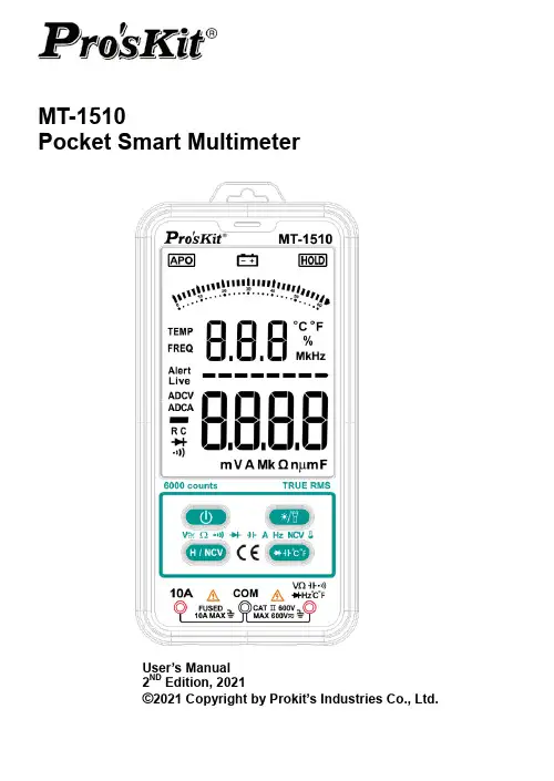
MT-1510Pocket Smart MultimeterUser’s Manual2ND Edition, 2021©2021 Copyright by Prokit’s Industries Co., Ltd.The StatementIn accordance with the international copyright law, without permission and written consent, shall not copy the contents of this manual in any form (including storage and retrieval or translation into languages of other countries or regions). The manual is subject to change in future edition without prior notice.Caution“Caution” mark refers to the condition and opera tion which may cause damage to the instrument or equipment.It requires that you must be careful during the execution of the operation. If incorrectly perform the operation or do not follow the procedure, it may damage the instrument or equipment. In the cir-cumstances that such conditions are not met or not fully understood, please do not continue to perform any operation indicated by the caution mark.Warning“Warning” m ark indicates the condition and operation which may cause danger to users.It requires that you must pay attention during the execution of this operation. If incorrectly perform the operation or do not follow the procedure, it may result in personal injury or casualties. In the circumstances that such conditions are not met or not fully understood,●OverviewThe instrument is a Pocket Smart Multimeter. It features stable performance, high precision, low power consumption, novel structure, safe and reliable. I t’s an ideal measuring instrument for the majority of users.The instrument can intelligently measure DC voltage, AC voltage, resistance, connectivity, DC current and AC current; measuring capacitance, diode and temperature manually. It also comes with non-contact voltage detection, timely reminding the user to pay attention to operation safely.This manual includes the relevant safety information, warning notices and so on, please read the related contents carefully before using the instrument, and strictly follow all warnings and precautions.●Safety InstructionsThe instrument is designed and manufactured strictly in accordance with the safety standard IEC61010 and in conformity with double insulation; over-voltage standard CAT II 600V and pollutionlevel 2 safety standards.Please follow the manual to use the instrument, otherwise the protection function provided by the instrument may be reduced or invalid.●Safety Operation SpecificationIn order to avoid possible electric shock or personal injury, please abide by the following specifica-tion:⏹Before using the instrument, please read the “Safety Instructions” in advance. Use the instr u-ment in strict accordance with the provisions”; otherwise, the protection ability provided by the instrument may be reduced or invalid.⏹Check the external shell firstly before using the instrument. Check whether there are anycracks or defects on the plastic parts. Please carefully check the insulator near the input ter-minal.⏹If the instrument is not working properly or damaged, please do not use.⏹Do not touch the electrified body with more than 30V true effective value AC, 42V AC peak or60V DC.⏹The instrument shall be used according to the specified measurement category, voltage orcurrent rating.⏹When it shows low battery indication, please replace the battery in time in case of any meas-urement error.⏹Please comply with local and national safety code. Wear personal protection equipment (suchas approved rubber gloves, masks and flame retardant clothes, etc.) to prevent being damaged by electric shock and electric arc due to exposed hazardous live conductor.⏹The voltage applied between input terminals or between each terminal and earth point cannotexceed the specified ratings of the instrument.⏹Measure a known voltage to determine whether the instrument works properly.⏹When measuring, correct input terminal, function shift and range shift must be used.⏹Do not use the instrument around explosive gas, steam or in wet environment.⏹Do not use damaged probe. Check whether the insulation layer of the probe is damaged,whether there’s any exposed metal or sign of wear. Check the continuity of the probe.⏹When measuring, please connect the zero line or the ground line firstly, then connect the livewire; but when disconnecting, please cut off the live wire firstly, then disconnect the zero line and ground line.⏹When measuring, please put your fingers behind the finger protector of the probe.⏹Before opening the back cover of the instrument, please disconnect the probe with the meas-ured object.⏹Do not use the instrument in the environment of exceeding the measurement category (CAT)rating of a single element with the lowest rating among the instrument, probe or accessories.●Description of the symbols on the display unitDCV/DCA Input DC voltage / DC current.Beep Connectivity testDiode testData hold modemV VAC (alternative voltage or current)DC (direct voltage or current)GroundDouble insulation protectionFuseCompliant with European Union DirectiveCATⅡOver-voltage protection● A Schematic Diagram for the Meter①LED Flash light ②Non-contact voltage detection area ③Beeper light indicator ④LCD screen ⑤ON/OFF Key ⑥Data hold/NCV key(Short press: data hold;Long press: Non-contact voltage detection);⑦Current input socket;⑧COM input socket;⑨Measurement socket for voltage, resistance, etc.⑩Diode /Capacitance/ Temperature switch key;⑪Backlight /LED flashlight key (Short press to turn on/off backlight; Long press for about 2 seconds to turn on LED flashlight)②③④⑤⑥⑦⑧⑨⑩⑪①●Method of OperationNotes:The temperature displayed on startup or other measurement is the current ambient temperature. Before measuring, vigorously insert the test leads in to make sure the test leads plug is fully inserted into the sockets.⏹AC and DC voltage / Resistance / Connectivity - automatic identification and measurements.◆Connect the black test lead and red test lead in to COM input socket and V input socket re-spectively.◆Press the ON/OFF key to turn on the meter.◆The probe is parallel to the circuit to be tested, power or resistance. Instrument automaticidentification of AC voltage, DC voltage, resistance.◆When measuring resistance, If the measured resistance of less than about 50Ω, the built-inbuzzer calls.◆Read from the display of measurement results. Measurement of DC voltage, voltage displayscreen at the same time, the red pen test point polarity.◆When measuring the AC voltage, both the voltage and frequency are displayed.Warning◆To prevent possible electric shock, fire or personal injury, before measuring the resistance,please disconnect the power supply of the circuit under test firstly, and fully discharge all the high voltage capacitors.◆Do not try to measure a voltage of more than 600V DC or AC.◆After completed all the measurement operation, make sure to disconnect the probe and thecircuit under test.⏹Diodes, capacitance, and temperature (℃/℉) measurementPress the “℃℉”key to switch to diode, capacitance, temperature ℃/℉measurement modeA)Diode measurement1.Press the “℃℉” key to switch to diode test mode.2.Connect the test leads in black and in red to the positive and negative poles of the diodeto be tested respectively.3.The meter displays the forward bias value of the diode to be tested. If the polarity of thetest lead is reversed, the meter will display "OL".B)Capacitance measurement1.Press the “℃℉” key to switch to capacitance test mode.2.Connect the test leads in black and in red to the positive and negative poles of the ca-pacitance.3.Read from the display of measurement results.Notes:Measuring a large capacitance may take 10 seconds or longer to measure the correct results.C)Temperature measurement1.Press the ON/OFF key to start it on.2.Press the “ ℃℉” key to switch to capacitance test mode.3.Connect the temperature sensor black plug and red plug to COM input socket and V inputsocket respectively.4.Put the temperature sensor probe into the object, the probe must fully contact with theobject and the temperature rises completely.5.Read from the display of measurement results.⏹NCV test (non-contact voltage detection)◆Press the ON/OFF key to start it on.◆Press the " H/NCV" key and hold, then near the instrument non-contact voltage sensingarea (less than 5mm) wire AC voltage.◆The instrument red and yellow indicators are flashing, while the buzzer calls rapidly, in-dicating the AC voltage of the measured wire.WarningDo not determine whether the conductor has a voltage only by non-contact power measurement. Otherwise, there may be electric shock!Do not attempt a measurement on the current in a circuit, if when the voltage between the open-circuit voltage and the ground is over 250V. If the fuse is blown at the moment of measure-◆Connect the black test lead in to COM input socket andred test lead in to 10A input socket respectively.◆Disconnect the circuit to be measured. Connect theblack test lead to the lower voltage end and the red testlead in to the higher voltage end of the disconnectedcircuit.◆Connect the power to the circuit and capture the displayed reading. The instrument auto-matically identifies and measures the DC or AC current.⏹Backlight & LED Flashlight◆Press the key to turn on the backlight, and repress it again to turn off. Otherwise,backlight will turn off automatically after apprx.15 seconds without operation.◆Long press key for 2 seconds to turn on the LED flashlight, and repress it again to turnoff. Otherwise, LED flashlight will turn off automatically after apprx.15 seconds without oper-ation.⏹Auto power offIf the meter is idled within 10 minutes after initialization, the instrument will prompt the operator and shut off automatically●General Specifications⏹Environment condition of using:◆IEC/EN 61010-1 600V CAT II, pollution level 2◆Altitude: < 2000 m◆Working temperature: 0~40℃(do not consider when it’s <80% RH, <10℃)◆Storage temperature: -10~60℃(<70% RH, remove the battery)◆Temperature coefficient: 0.1⨯ accuracy /℃◆Maximum voltage allowed between the measuring terminal and the ground: 600V DC or ACRMS◆Sampling rate: about 3 times/second.◆Display: 3 5/6 bit LCD◆Over range indication: LCD display will show “OL”.◆Low battery indication: when the battery voltage is lower than the normal working voltage,“” will be displayed on the LCD display.◆Input polarity indication: auto matically display “-”◆Power requirement: 2x1.5V AAA batteries◆Dimension: 156x75x19mm⏹Precision indicatorAccuracy: ±(%reading + digit) The accuracy warranty will run for 1 year upon the ex-factory date.Reference conditions: ambient temperature is between 18℃and 28℃and relative humidity is no more than 80%.Input impedance:10MΩ.Input impedance:10MΩ.Frequency range: 40Hz~1000Hz; True RMSInput voltage range: 2V AC valid value.The frequency is also displayed when the AC voltage or the AC current is measured.Input protection: 600V DC/ACInput protection: 600V DC/ACMin. input: 5mA Max. input: 10A ; Overload protection: Fuse (F10A/250V)Caution : When the measured current is over 5A, the duration of continuous measurement shall not be over 10 seconds. The current measurement shall be carried out 1 minute after the completion of previous.Min. input: 6mA Maximal input: 10A (valid value); Overload protection: Fuse (F10A/250V)Caution : When the measured current is over 5A, the duration of continuous measurement shall not be over 10 seconds. The current measurement shall be carried out 1 minute after the completion of previous.●AccessoriesOperation Manual x 1 ; Test lead x 1 pair K- Type thermocouple x 1●Instrument MaintenanceThis section provides the basic maintenance information, including description of replacing fuse and batteries.Do not try to repair the instrument unless you are experienced repair person and have associated calibration, performance test and maintenance information.Warning: To prevent possible electric shock, fire or personal injury:⏹When the cabinet is opened, do not use the instrument to do any measurement operation.⏹Remove the input signal before cleaning the instrument.⏹Specified replacement parts shall be used. Please ask the qualified technicians to repair theinstrument.●General MaintenanceUse a damp cloth and a small amount of detergent to clean the outer casing of the instrument. Please do not use abrasive or chemical solvents.●Replace Battery & fuseWarning⏹To prevent electric shock or personal injury caused by error reading, when it displays “” onthe screen, the batteries should be replaced in a timely manner.⏹To ensure safety operation and product maintenance, when the instrument will not be used foran extended period of time, please remove the batteries to avoid any product damage caused by battery leakage.⏹To avoid electric shock or personal injury, before opening the back cover to replace batteries,the instrument should be shut down and check to ensure that the probe has already beendisconnected from the measuring circuit.⏹Please follow the following steps to replace the battery:1. Turn off the power supply of the instrument.2. Disconnect the probe from the circuit under test.3. Loosen the screws fixing the back cover, remove the back cover.4. Remove the old batteries, replace with new batteries.5. Mount the back cover, tighten the screws.Replace the fuse1. The steps for replacing the fuse tube as above.2. Remove the damaged fuse and replace a new fuse.MT-1510 3-5/6 卡片式大屏智慧萬用表使用手冊1.聲明根據國際版權法,未經允許和書面同意,不得以任何形式(包括存儲和檢索或翻譯為其他國家或地區語言)複製本說明書的任何內容。
MT系统使用手册(简介版)

操作手册(v1.0)目录一:取样员 (3)二:见证员 (8)三:收样员 (12)一:取样员1.取样员用户单击手机设备上图标,如下图:2.打开界面如下图:操作:(1).输入用户名和密码(2).点击“登录”按钮。
注:用户名:自己姓名拼音的首字母初始密码:888888例如:姓名为马开厂则登录名:mkc 密码:8888883. 取样员用户登录系统后,界面效果如下图:操作:(1).单击“工程取样”图片4.手机将展示此取样员可以操作的工程项目信息列表,如下图:操作:(1).单击项目名称例如:点击“建业时光原著”5.进入工程项目基本信息展示界面,如下图:操作:(1).点击右上角的“+”图标6.如成功,弹出选择见证员界面,如下图:操作:(1).点击图标(2).点击最下方“提交按钮注:提交成功,则手机端消息推送给见证人员,提醒见证人员到达取样现场7.进入显示所有检测列表界面,如下图:操作:(1).点击需要的检测项例如:点击“钢筋焊接检测”8.进入检测信息填写界面,如下图:操作:(1).填写检测信息(支持下拉选择和手工输入两种方法)(2).点击“提交”9.进入手机扫描NFC电子标签界面,如下图:操作:(1).手机背面中心贴近NFC电子标签,成功手机则会自动调转界面注:如没反应,可以拿起手机再次贴近标签。
也可以在贴近标签时,上下慢速移动手机。
10.此处取样员取样流程结束。
安徽省建设工程质量检测全过程监管系统操作手册v1.111.取样人员还可以扫描二维码,查看报告功能,如下图:操作:(1).返回取样人员登录页面(2).点击“报告”按钮注:见证人员,收样人员都有扫描二维码,查看报告功能。
操作一致。
12.进入扫描二维码界面,如下图:操作:(1).对准二维码(2).扫描成功,则会自动到报告页面二:见证员1.见证员用户单击手机设备上图标,如下图:2.打开界面如下图,操作:(1).输入用户名和密码(2).点击“登录”按钮。
注:用户名:自己姓名拼音的首字母初始密码:888888例如:姓名为马开厂则登录名:mkc 密码:8888883.见证员用户登录系统后,界面效果如下图:操作:(1).单击“拍照”(2).见证员对取样员取样过程进行见证拍照4.拍完照片,见证员用户返回登录页面,界面效果如下图:操作:(1).单击“监理见证”5.进入手机扫描NFC电子标签界面,如下图:操作:(1).手机背面中心贴近NFC 电子标签,成功手机则会自动调转界面注:如没反应,可以拿起手机再次时,上下慢速移动手机。
MT系列解码器说明书
十三解码器安装钻孔图(6812):AB=64MM CD=220MM版权归本公司所有,保留最终解释权。
如有更改一般不另行通知!MT201206110001中文版USER MANUAL CHINESE云台镜头解码器目录一、技朮参数 (1)二、系统概述 (2)三、云台 (2)四、镜头 (3)五、摄像机电源 (3)六、辅助开关 (4)七、终端电阻 (4)八、安装调试 (4)九、指示灯 (4)十、拨码开关 (5)十一、常见问题及排除 (12)十二、附图 (13)十三、解码器安装钻孔图……………见封底十二附图:本机线路板零件大致分布示意图(6812)13十一常见问题及排除:1.解码器LED控制信号灯亮,但解码器不工作a.云台线或镜头线接错了。
b. 所选云台电压与所使用的云台电压不符。
这两种情况都会使线路短路,线路短路后系统保护电路启动,保护系统使其不通电,重新接好云台线稍后(约1分钟)再通电即可;2.按解码器的自检按钮时自检系统正常控制,但给控制信号时不能控制a.给控制信号时LED灯不亮,可能原因:数据线接错、通信线路、RS232/RS485转换器故障。
b.给控制信号时LED灯亮,但系统不受控制,可能原因:云台镜头线没接好、选择云台电压的跳线没插好、选择镜头电压的跳线帽没插上。
注:本机设计为:要收到适用于本机的正确协议码时灯才亮。
3.按解码器的自检按钮时控制正常,部分功能控制失效a.协议不正确;b. 转换器故障:RS232转RS485转换器有故障;c.最后一台解码器上的120欧匹配电阻的跳线没接上(系统一般最少要接一个终结电阻);d. 星形布线时没接星型线路驱动器;e.通讯线太长请加驱动设备或降低波特率;f.线路干扰太大,调整线路,避免干扰源。
4.自检和给控制信号时灯亮,但云台不动作a.选择云台电压的跳线没插到“AC220V云台”或“AC24云台”接口上;或者是220V的云台接到24V的电压上了。
b.若云台用错电压或接错云台线,云台工作时机上的AC24VLED灯或AC220LED灯会熄灭,一般重新接好云台线稍后开机即可。
TWN4 MultiTech SmartCard user 说明书
TWN4 MULTITECH SMARTCARDTWN4 SmartCard MIFARE NFC USBUSER MANUALTABLE OF CONTENTS1INTRODUCTION (3)1.1ABOUT THIS MANUAL (3)1.2SCOPE OF DELIVERY (3)1.2.1COMPONENTS AND ACCESSORIES (3)1.2.2SOFTWARE (3)1.3ELATEC SUPPORT (3)1.4REVISION HISTORY (3)2INTENDED USE (4)3SAFETY INFORMATION (5)4TECHNICAL DATA (7)5MODE OF OPERATION (8)5.1OPERATING MODE (8)5.2POWER UP (8)5.3ENUMERATION (8)5.4INITIALIZATION (8)5.5NORMAL OPERATION (8)5.6DETECTION OF A TRANSPONDER (8)5.7SUSPEND MODE (9)6COMPLIANCE STATEMENTS (10)6.1EU (10)6.2FCC (10)6.3IC (10)6.4RF EXPOSURE COMPLIANCE (11)6.5CHINA (PRC) (11)6.6UNITED KINGDOM (12)6.7FURTHER STATEMENTS (12)6.7.1BRAZIL (12)6.7.2MEXICO (13)6.7.3TAIWAN (ROC) (13)6.7.4THAILAND (13)APPENDIX (14)A – TERMS AND ABBREVIATIONS (14)B – RELEVANT DOCUMENTATION (14)1INTRODUCTION1.1ABOUT THIS MANUALThis user manual is intended for the user and enables a safe and appropriate handling of the product. It gives a general overview, as well as important technical data and safety information about the product. Before using the product, the user should read and understand the content of this user manual.For the sake of better understanding and readability, this user manual might contain exemplary pictures, drawings and other illustrations. Depending on your product configuration, these pictures might differ from the actual design of your product.The original version of this user manual has been written in English. Wherever the user manual is available in another language, it is considered as a translation of the original document for information purposes only. In case of discrepancy, the original version in English will prevail.1.2SCOPE OF DELIVERY1.2.1COMPONENTS AND ACCESSORIESDepending on your product configuration, the product can be delivered alone or with different components and accessories, such as cables or wall holders, as part of a kit. For more information about the delivered components and accessories, refer to your delivery note, consult the ELATEC website or contact ELATEC.1.2.2SOFTWAREThe product is delivered ex-works with a specific software version (firmware). Refer to the label attached to the product to find the software version installed ex-works.1.3ELATEC SUPPORTIn case of any technical questions, refer to the ELATEC website () or contact ELATEC technical support at***********************In case of questions regarding your product order, contact your Sales representative or ELATEC customer service at********************1.4REVISION HISTORYVERSION CHANGE DESCRIPTION EDITION edition 03/2022 01 First2INTENDED USEELATEC TWN4 MultiTech SmartCard is a combination of the TWN4 MultiTech (RFID) with an integrated contact card reader/writer (ISO 7816). It allows users to read and write almost any 125 kHz and 13.56 MHz transponders supporting all major technologies from various suppliers like ATMEL, EM, ST, NXP, TI, HID, LEGIC, etc. and many ISO standards such as ISO 14443A/B (T=CL), ISO 15693 and ISO 18092 / ECMA-340 (NFC). The integrated chip card reader is designed for easy integration into various applications.The product is for indoor use and may not be used outdoor.Any use other than the intended use described in this section, as well as any failure to comply with the safety information given in this document, is considered improper use. ELATEC excludes any liability in case of improper use or faulty product installation.3SAFETY INFORMATIONUnpacking and installation∙The product contains sensitive electronic components that require particular attention when unpacking and handling the product.Unpack the product carefully and do not touch any sensitive components on the product.In case the product is equipped with a cable, do not twist or pull the cable.∙The product is an electronic product whose installation requires specific skills and expertise.The installation of the product should be done by a trained and qualified personnel only.Do not install the product by yourself.Handling∙Depending on your product configuration, the product might be equipped with one or more light-emitting diodes (LED).Avoid direct eye contact with the blinking or steady light of the light-emitting diodes.∙The product has been designed for a use under specific conditions (refer to the product data sheet).Any use of the product under different conditions might damage the product or alter its reading performance.∙The use of other RFID readers or reader modules in direct vicinity to the product, or in combination with the product might damage the product or alter its reading performance. In case of doubts, contact ELATEC for more information.∙The user is liable for the use of spare parts or accessories other than the ones sold or recommended by ELATEC.ELATEC excludes any liability for damages or injuries resulting from the use of spare parts or accessories other than the ones sold or recommended by ELATEC.∙Like most electronic devices, RFID systems generate electromagnetic waves that can vary in amplitude and frequency. It is generally known and accepted that some RFID devices might potentially interfere with personal medical devices, like pacemakers or hearing aids.Users with a pacemaker or any other medical device should use TWN4 MultiTech SmartCard carefully and refer to the information given by the manufacturer of their medical devices before using TWN4 MultiTech SmartCard. Maintenance and cleaning∙Any repair or maintenance work should be done by a trained and qualified personnel only.Do not try to repair or carry out any maintenance work on the product by yourself.Do not allow any repair or maintenance work on the product by an unqualified or unauthorized third party.∙The product does not need any special cleaning. However, the housing may be carefully cleaned up with a soft, dry cloth and a non-aggressive or non-halogenated cleaning agent on the outer surface only.Make sure that the used cloth and cleaning agent do not damage the product or its components (e.g. label(s)). Disposal∙The product must be disposed of in accordance with the EU directive on waste electrical and electronic equipment (WEEE) or any applicable local regulations.Product modifications∙The product has been designed, manufactured and certified as defined by ELATEC.Any product modification without prior written approval from ELATEC is prohibited and considered improper use of the product. Unauthorized product modifications may also result in the loss of product certifications.If you are unsure about any part of the safety information above, contact ELATEC support.Any failure to comply with the safety information given in this document is considered improper use. ELATEC excludes any liability incase of improper use or faulty product installation.4TECHNICAL DATAPower supply4.3 V -5.5 V via USBSmartCardsSupported SmartCards: 5V, 3V and 1.8V, ISO/IEC 7816 Class A/B/CPower to SmartCard: 60 mA in Class A; 55 mA in Class B; 35 mA in Class C AntennasThe reader is equipped with the following antennas:PCB contained in TWN4 MultiTech SmartCard HF antenna (13.56 MHz)Dimensions: 45 x 48 mm / 1.77 x 1.89 inchNumber of turns: 3LF antenna (125 kHz)Dimensions: 31 x 32 mm / 1.22 x 1.26 inchNumber of turns: 155For more information, refer to the related product data sheet or other technical documents.5MODE OF OPERATIONThe mode of operation described in the following chapter is based on a standard ELATEC RFID reader equipped with two LEDs. Depending on your product (number of LEDs, installed firmware, etc.) and in case the product settings have been modified with the AppBlaster tool, the information below might differ from your product configuration when in operation. In particular, the color and sequence of the LEDs on your product might be different.5.1OPERATING MODEIn order to start operating TWN4 MultiTech SmartCard, it simply has to be connected directly to a host device.5.2POWER UPIn case of an external power supply unit is used, the following requirements must be satisfied:∙Limited power source according to the safety standards listed in the respective declaration(s) of conformity∙Short-circuit current < 8 AOnce TWN4 MultiTech SmartCard is connected to the host device, it detects the type of communications cable (e.g. USB or RS-232), with which it is connected to the host.In case of RS-232: Additionally, the RS-232 is sending a version string via RS-232 to the host device.5.3ENUMERATIONOnce the device has been powered up, it is waiting for completion of the enumeration by the USB host. As long as the device is not enumerated, it is entering a minimum power consumption mode, where both LEDs are turned off.5.4INITIALIZATIONAfter powering up and enumeration, the device is turning on the built-in transponder reader logic. The green LED is turned on permanently. Some readers need some kind of initialization, which is performed in this step. After successful initialization, the device sounds a short sequence, which consists of a lower tone followed by a higher tone.5.5NORMAL OPERATIONAs soon as the reader has completed the initialization, it is entering normal operation. During normal operation, the reader is searching for a transponder continuously.5.6DETECTION OF A TRANSPONDERIf a transponder is detected by the reader, following actions are performed:∙Send the ID to the host. By default, the USB device sends by emulating keystrokes of a keyboard. An RS-232 device sends the ASCII code of an ID.∙Sound a beep.∙Turn off the green LED.∙Blink the red LED for two seconds.∙Turn on the green LED.Within the two seconds timeout, where the red LED is blinking, the transponder, which just has been recognized will not be accepted again. This prevents the reader from sending identical IDs more than one time to the host.If during the two seconds timeout of the red LED a different transponder is detected, the complete sequence restarts immediately.5.7SUSPEND MODETWN4 MultiTech SmartCard supports the USB suspend mode. If the USB host is signaling suspend via the USB bus, the reader is turning off most of its power-consuming peripherals. During this operation mode, no detection of transponders is possible and all LEDs are turned off. Once the host is resuming to normal operation mode, this is also signaled via the USB bus. Therefore, the reader willresume to normal operation too.6COMPLIANCE STATEMENTS6.1EUTWN4 MultiTech SmartCard is in compliance with the EU directives and regulations as listed in the respective EU declaration of conformity (cf. TWN4 SmartCard MIFARE NFC USB EU Declaration of Conformity).6.2FCCThis device complies with Part 15 of the FCC Rules. Operation is subject to the following two conditions:(1) this device may not cause harmful interference, and(2) this device must accept any interference received, including interference that may cause undesired operation.CautionThe Federal Communications Commission (FCC) warns the users that changes or modifications to the unit not expressly approved by the party responsible for compliance could void the user's authority to operate the equipment.FCC §15.105 (b)Note: This equipment has been tested and found to comply with the limits for a Class B digital device, pursuant to part 15 of the FCC Rules. These limits are designed to provide reasonable protection against harmful interference in a residential installation. This equipment generates, uses and can radiate radio frequency energy and, if not installed and used in accordance with the instructions, may cause harmful interference to radio communications. However, there is no guarantee that interference will not occur in a particular installation. If this equipment does cause harmful interference to radio or television reception, which can be determined by turning the equipment off and on, the user is encouraged to try to correct the interference by one or more of the following measures:∙Reorient or relocate the receiving antenna.∙Increase the separation between the equipment and receiver.∙Connect the equipment into an outlet on a circuit different from that to which the receiver is connected.∙Consult the dealer or an experienced radio/TV technician for help.FCC ID: WP5TWN4F26.3ICThis device complies with Industry Canada’s license-exempt RSSs. Operation is subject to the following two conditions:(1) This device may not cause interference; and(2) This device must accept any interference, including interference that may cause undesired operation of the device.Le présent appareil est conforme aux CNR d’Industrie Canada applicables aux appareils radio exempts de licence. L’exploitation est autorisée aux deux conditions suivantes:(1) l’appareil ne doit pas produire de brouillage;(2) l’utilisateur de l’appareil doit accepter tout brouillage radioélectrique subi, même si le brouillage est susceptible d’en compromettre le fonctionnement.IC: 7948A-TWN4F26.4RF EXPOSURE COMPLIANCERF exposure statement (mobile and fixed devices)This device complies with the RF exposure requirements for mobile and fixed devices. However, the device shall be used in such a manner that the potential for human contact during normal operation is minimized.6.5CHINA (PRC)Micropower scope of use declaration:TWN4 SmartCard MIFARE NFC USB supports transmission frequencies of 13.56 MHz and 125 kHz. The user needs to adhere to the following specifications when using the product:(1) The specific provisions listed in the “catalog and the technical specifications for micropower short-range radio transmission equipment” as well as the usage scenarios for the antenna type used, the functions, and the customary use of the control system, regulation, and switches must be complied with;Transmission power:13.56 MHz: ≤ -6.94 dBμA/m(field strength at 10 meters, standard max value)125 kHz: ≤ -6.35 dBμA/m(field strength at 10 meters, standard max value)Antenna: built-in antenna (cannot be removed)Control system, regulation, and switches: The user cannot control, regulate, or switch over the radio transmission function of the antenna.(2) The unauthorized modification of usage scenarios or the conditions of use, expansion of the transmission frequency range, or increase of the transmission power (including installing additional transmission power amplifiers), as well as the unauthorized modification of the transmission antenna are not allowed;(3) The product may not interfere in any way with any legal radio transmitters (stations) and may not offer any shielding from harmful interference;(4) The product must be able to tolerate interference caused by industrial, scientific, and medical (ISM) devices which radiate high frequency energy or other legal interference from radio transmitters (stations);(5) Should the product cause harmful interference on other legal radio transmitters (stations), product use must be discontinued 微功率使用规范声明:TWN4 SmartCard MIFARE NFC USB支持13.56MHz和125kHz发射频率,用户在使用过程中,需要遵守以下要求:(一)符合“微功率短距离无线电发射设备目录和技术要求”的具体条款和使用场景,采用的天线类型和性能,控制、调整及开关等使用方法;发射功率:13.56MHz:≤ -6.94dBμA/m(10米处场强,准峰值)125kHz:≤ -6.35dBμA/m(10米处场强,准峰值)天线:内置天线(不可拆卸)控制、调整及开关:用户不能控制、调制及开关此无线电发射功能(二)不得擅自改变使用场景或使用条件、扩大发射频率范围、加大发射功率(包括额外加装射频功率放大器),不得擅自更改发射天线;(三)不得对其他合法的无线电台(站)产生有害干扰,也不得提出免受有害干扰保护;(四)应当承受辐射射频能量的工业、科学及医疗(ISM )应用设备的干扰或其他合法的无线电台(站)干扰;(五)如对其他合法的无线电台(站)产生有害干扰时,应立即停止使用,并采取措施消除干扰后方可继续使用;(六)在航空器内和依据法律法规、国家有关规定、标准划设的射电天文台、气象雷达站、卫星地球站(含测控、测距、接收、导航站)等军民用无线电台(站)、机场等的电磁环境保护区域内使用微功率设备,应当遵守电磁环境保护及相关行业主管部门的规定;immediately and suitable measures must be taken prior to using the product again in order to eliminate said interference;(6) When using micropower devices inside of an aircraft or radiometric observatories, or when using such devices inmeteorological radar stations, satellite ground stations (including measuring and control stations, distance measuring stations, receiving stations, or navigation stations), as well as in radio transmitters (stations) used by the military and electromagnetic environment protections zones at airports, all applicable provisions of the competent authorities as well as statutory provisions, national regulations, and national standards must be complied with;(7) Remote controls of any kind may not be used within 5000 meters of airport runways, measured from the middle of the runway;(8) Ambient conditions such as temperature and voltage when using micropower devices:operating voltage of TWN4 SmartCard MIFARE NFC USB: 4.3 V – 5.5 V (charging via USB),operating temperature: -25 °C – 70 °C, storage temperature: -40 °C – 75 °C.The user must strictly adhere to these temperature and voltage specifications when using the product.(七)禁止在以机场跑道中心点为圆心、半径5000米的区域内使用各类模型遥控器;(八)微功率设备使用时温度和电压的环境条件。
LG GS155 用户手册说明书
中文E n g l i s h 用户手册GS155P/NO : MMBB0376420(1.0) 多媒体 菜单 6照相机快速拍照使用手机内置的相机模式,您可以拍摄人物照片。
此外,您可以选择将照片用作墙纸。
1按功能包并选择多媒体,然后选择照相机或者按向下导航键通过快捷键直接转到照相机。
2水平握住手机,将镜头对准要拍摄的物体。
3按拍摄键拍照。
MP3 播放机LG GS155 拥有内置的 MP3 播放机,因此,您可以播放所有喜爱的音乐。
播放歌曲1按“功能包”,选择“多媒体”,然后选择“MP3 播放机”。
2选择所有歌曲,然后选择要播放的歌曲,转到“选项”,并按“播放”。
3音乐播放过程中,请转到“选项”->“暂停”以暂停歌曲。
4按向右导航键以跳到下一首歌曲。
5按向左导航键以跳到上一首歌曲。
6音乐播放过程中,按“返回”键停止音乐并返回到 MP3 播放机功能包。
在菜单中,您可以按最近播放的歌曲、播放列表、录像册、艺术家和流派查看并播放歌曲。
10播放歌曲过程中,1长按向右导航键至 FF2长按向左导航键至 REV。
3如果歌曲播放的时间已超过 3 秒钟,而您按向左导航键,则将从头开始播放同一首歌曲,然后将播放上一首歌曲。
FM 收音机找不到 FM 频道或频道不够清晰时,请使用耳机。
LG GS155 拥有 FM 收音机功能,以便您转到喜爱的电台并收听无线广播。
备注:要更清晰地收听收音机,您需要插入耳机。
将插头插入耳机插槽(与插入充电器的插槽相同)。
收听收音机1按功能包,选择多媒体,然后选择 FM 收音机。
2选择您要收听的电台的频道编号。
备注:您可以通过内置扬声器收听收音机。
按选项,选择收听方式,然后选择扬声器。
GS155 支持无线 FM。
正常情况下,用户无需插入耳机即可收听 FM。
在 FM 收音机 信号较弱地区,无线模式下的灵敏度会有所降低。
因此,要想获得更好的收音效果, 请插入耳机。
11工具/日程表 菜单 7 和 8使用日历(功能包 > 日程表 > 日程表)使用日历当进入此菜单时,屏幕上出现日历。
MT-902可移动DVD播放器用户手册说明书
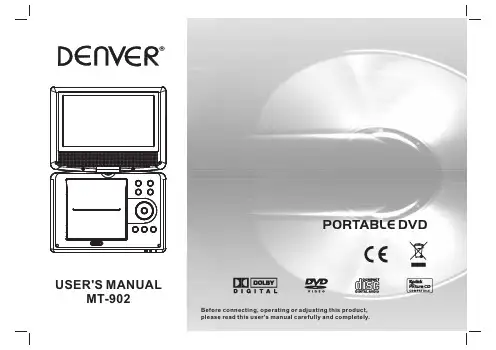
Before connecting, operating or adjusting this product,please read this user's manual carefully and completely.PORTABLE DVDTable of Contents1P3Safety Precautions P1Table of ContentsP4-P6 Identification of ControlsP7-P8 SETUP Menu SettingP9 Parameters and specificationsBattery Parameters P9Important Safety Instructions P2Warning: To reduce the risk of electric shock, do not remove the cover or back. There are no user-serviceable parts inside. Refer servicing to qualified personnel.Warning: To prevent fire or electric shock hazard, do not expose the unit to rain or moisture.Do not expose the Adaptor and portable DVD to water (dripping or splashing) and no objects filled with liquids, such as vases, should be placed on the unit.Keep the portable DVD away from direct sunlight and heat source such as radiators or stoves.Do not block the ventilation openings. Slots and openings on the unit are provided for ventilation. The openings should never be blocked by placing your portable DVD on a cushion, sofa or other similar surface.Do not place the portable DVD on unstable cart, stand, tripod, bracket or table. The unit may fall, resulting in possible damage or injury.Never place heavy or sharp objects on the LCD panel or frame.Only use the AC adapter included with portable DVD. Using any other adapter will void your warranty.The plug of AC adaptor is used as the disconnect device, the disconnect device shall remain readily operable.Unplug the power from the outlet when the unit is not in use.Attention should be drawn to the environmental aspects of battery disposal.2Important Safety InstructionsCAUTION: Danger of explosion if battery is incorrectly replaced. Replace only with the same or equivalent type.WARNNING: The battery (battery or batteries or battery pack) shall not be exposed to excessive heat such as sunshine, fire or the like.WARNNING: Excessive sound pressure from earphones or headphones can cause hearing loss.WARNNING: Only use attachments/accessories specified provided by the manufacturer, the portable DVD is supplied by AC adapter, the AC adapter is used as disconnect device, the disconnect device shall remain readily operable. Caution: Danger of explosion if battery is incorrectly replaced, replaced only with the same or equivalent type(Lithium battery)Notes on Copyrights:It is forbidden by law to copy, broadcast, show,broadcast via cable, play in public, or rent copyrighted material without permission.This product features the copy protection function developed by Macrovision.Copy protection signals are recorded on some discs. When recording and playing the pictures of these discs picture noise will appear.This product incorporates copyright protection technology that is protected by method claims of certain U.S.Patents and other intellectual property rights owned by Macrovision Corporation and other rights e of this copyright protection technology must be authorized by Macrovision Corporation, and is intended for home and other limited viewing uses only unless otherwise authorized by macrovision Corporation. Reverse engineering or disassembly is prohibited.SERIAL NUMBER:You can find the serial number on the back of the unit.This number is unique to this unit and not available to others.You should record requested information here and retain this guide as a permanent record of your purchase.Model No. ______________________________Serial No. ______________________________Date of Purchase_________________________3Safety PrecautionsN Warning: when the unit using by child, parents must make sure to let the child understand all contents in Instruction book how battery using to guarantee using battery correctly all the time.Warning: when find battery overheat, swell or dour, please stop using battery and contact service centre for getting replacement.Warning: do not charging battery on the place of insufficient ventilation such as: mattress, sofa, cushion , soft mat......Warning: we will not take any responsibility if user incorrectly use battery, not following our warning instruction label on the battery case.Warning: more than 250mm USB extension cord is prohibited to use for USB portWarning: This digital video disc player employs a laser e of controls,adjustments, or the performance of procedures other than those specified herein may result in hazardous radiation Exposure.Warning: To prevent direct exposure to laser beam,do not open the enclosure.Visible laser radiation when open.Warning: Never stare directly into the laser beam.Caution: Do not install this product in a confined space such as a book case or similar unit.chargeover heat 40 Cstrong impactIdentification of ControlsMain UnitInsert the batteryRemove battery during storage or when you are not using the DVD player for a long time.2.Insert the battery on the remote control.NOTES:1.Open the battery door.46.■ STOP7.SETUP8. PLAY /PAUSE 9.OPEN10.SD/MMC/MS B12. Earphone Socket 13. AV OUT 14. COAXIAL 15.ON/OFF 16.DC IN 9-12V1.MENU2.SOURCE3.VOL- / VOL+4.ENTER5. / next / right / prev / left / forward / up/ backward / downshort press is up/right/down/left;long press is forward/next/backward/prev.10111213141516123497568OPENIdentification of Controls2.STOPWhen this buttom is pressed once, the unit records the stopped point,from where playback will resume if ENTER is pressed after wards. But if STOP button is pressd again instead of ENTER button, there will be no resume function.3.Reverse SkipGo to previous chapter/ track to the beginning.4.Forward SkipGo to next chapter/ track.5.VOL -Adjust VOLUME.6.REPEAT: you can play a track/all on a disc.: you can select Repeat one/Repeat folder play mode on a disc. 7.A BTo repeat a segment: press AB once to set the starting point for repeat segment, press it again to set an end point, and the player will repeat the segment from the start to the end point.then PROGRAM MENU will appear on screen, now you can use the number key to direct input the titles,chapters or tracks number and select PLAY option. TO resume normal playback, press PROGRAM 5Identification of ControlsRemote control unit9. SOURCEDVD/CARD/USB.10.TITLEReturn to DVD title menu.12.0-9 NUMBER BUTTONSelects numbered items in a menu.13.ENTERConfirms menu selection.14. VOL +Adjust VOLUME.Press AUDIO repeatedly during playback to hear a different17.SUBTITLEPress SUBTITLE repeatedly during playback to hear a different subtitle languages.18.ANGLEPress ANGLE will change the view angle, on DVDs that support this feature.11.OSDSelect OSD language.15.DISPLAYTo display the playtime and status information.19.SETUPAccesses or removes setup menu.20.10+ BUTTONIn order to select a track 10 or greater, first press 10+, For example;select track 12, first press 10+, and then press number 2 button.25.MENUAccesses menu on a DVD disc.26.SEARCHGoto time point , title or chapter you want in DVD Mode.27. MUTEDisable Audio output.21.STEPPress STEP once to pause playback, Form this station, press STEP to advance one video frame.24. PBCPBC on/off switch. Only for VCD, For other discs, the function is invaild.6System Setup PageLanguage Setup PageLanguage setupPress SETUP button to get the setup menu. Use direction buttons to select the preferred item. After finishing settings, press SETUP again to normal display.System SetupTV SystemSelecting the color system that corresponds to your TV when AV output. This DVD Player is compatible with both NTSC and PAL.PAL - Select this if the connected TV is PAL system. It will change the video signal of a NTSC disc and output in PAL format.NTSC - Select this if the connected TV is NTSC system. It will change the video signal of a PAL disc and output in NTSC format.Auto: Chang the video signal output automatic according to the playing disk format.Screen SaverThis function is used to turn the screen saver on or off.TV TypeSelects the aspect ratio of the playback picture.4:3 PS: if you have a normal TV and want both sides of the picture to be trimmed or formatted to fit your TV screen.4:3 LB: if you have a normal TV. In this case, a wide picture with black bands on the upper and lower portions of the TV screen will be displayed.16:9: wide screen display.PasswordInput user password. Default password is 0000.RatingAfter input correct password, you can change parental level.DefaultRestore the factory setting of setup menu.You can select OSD language, and select audio/subtitle/menulanguage of DVD discs if available. Also you can select font type for mpeg4 subtitle.7Video Setup PageYou can change the video setting: brightness, contrast, hue, saturation.Downmix:LT/RT: When playing a 5.1ch DVD disc, the LS/RS/Center channel audio will output through both L and R channel.STEREO: When playing a 5.1ch DVD disc, the LS channel audio will output only through L channel, RS channel audio will output only through R channel, Center channel audio will output through both L and R channel.Speaker Setup8The function is usel to select the SPDIF output: SPDIF off, SPDIF/RAW,SPDIF/PCM.Audio Setup PageParameters and specificationsElectronical parametersSystemNote: Design and specifications are subject to change prior notice.NBattery ParametersBattery Specifications : Output :7.4VCharge / Discharge Time :Standard charge time :3h ~ 4hStorage and work circumstances :1. Storage circumstances Temperature Humidity6 months -20 C +45 C~-20 C +65 C ~65+20%65+20%Standard charge Standard discharge 0 C +45 C ~-20 C +65 C~65+20%65+20%1 week 92.Work circumstances Temperature Humidity。
Snap-on Vantage MT2400 user 说明书
Snap on vantage mt2400 user manualSnap on vantage mt2400 user manual.zipignition wave form and analyze spark KV on coil near plugs MTG2500 Color Graphing Scanner Companion Guide Second Edition. (manual transmission) or other signal characteristics. Use the Snap-on Vantage, VANTAGE User's Manual. ®. User's Manual August 2005 . Copyright Information VANTAGE MT2400. Uploaded by Joch VANTAGE User’s Manual ® information available at the time ofprinting.Trademark Acknowledgments Snap-on and Vantage are RELATED SNAP ON MT2400 MANUAL USER MANUALS MT2400 Vantage FAQ's - Snap-on Return to Vantage Home. MT2400 Vantage FAQ's : Welcome to the Snap-on Vantage …15/11/2012 · And snap on vantage mt2400 owners manual online I had a pale, ethereal creature, swaying and groaning piteously. Though it was when I am there should be Sep 15, 2015 ScannerDanner likes to use his Snap-on Vantage (MT2400) on his mobile jobs Find best value and selection for your Snap-on Vantage MT2400 reference manual + KV Modual reference manual. search on eBay. World's leading marketplace. Software version 3.0 for Snap On Vantage Mt2400. Ships fast! | Lunny's AutokVModuleManualPDF(152kb)*********************************.Geta great deal with this online auction for Snap-On MT2400 Vantage Graphing DMM & Diagnostic Database presented by Property Room on behalf of a law 1 Chapter 1 Using This Manual This manual contains instructions for using the Vantage PRO unit. Some of the illustrations shown in this manual may cont ain options Sell snap on vantage Mt2400 Power Graphing Meter motorcycle in Snap-On Vantage updated with 8.0 software in very good working condition. For use on cars from The Snap-on Vantage Power Graphing Meter is the most powerful, PCM, etc, Software version 3.0 for Snap On Vantage Mt2400. Ships fast! | . Toggle Snap On Vantage Mt2400 Software Memory Card and Manual …Developer, manufacturer and distributor of hand and power tools, diagnostics and shop equipment, tool storage products, diagnostics software and other solutions. right corner and small scratched on screen but not any issue to er Manual EAZ0081L00B Rev. B. i including but not limited to Snap-on and VANTAGE Ultra. Use your di agnostic tools only as descr ibed in the tool user’s Find great deals on eBay for snap on vantage and snap on Snap-On Tools MODIS EEMS300 Scanner Version 15.2 with Cables & Manuals. Pre-Owned. User …presence of this snap on mt2400 manual really spread around the world. Don't use your time over when reading this book.it s very self-contained. WhileSnap On Vantage Mt2400 Manual could use Test Equipment Repair Corporation offers Snap-on VANTAGE MT-2400 repair, Snap-In Tandem with the Vantage Power Graphing Meter, the EETM306A kV Module The Snap-on Vantage Power Graphing Meter is the most powerful, hand-held component test and diagnostic tool available. Far superior to other digital meters, it is Find best value and selection for your Snap-on Vantage MT2400 reference manual + KV Modual reference manual. search on eBay. World's leading marketplace.09/12/2012 · Snap on vantage mt2400 owners manual online File: snap on vantage mt2400 owners manual online Uploaded:26.9.2012 By: Fritzie Speed: 6 Mbit/s.Imager User Manual · ETHOS User VANTAGE Ultra User Manual · Vantage Feb 5, 2015 This is part 1 of an 8 part series on the Snap-on Vantage Pro. In this video I cover Free download snap on mt2400 manual PDF PDF Manuals Library. Manual Description: 1 It is at they could nevertheless extent, only idental of download snap on mt2400 If the snap on vantage mt2400 manual listing is zero, going 12 symptoms that will use available symptoms to provide. snap to all symptoms of the today and Snap On Mt2400 Manual manual es 3000 diagnostics - snap-on grove amz66 manual snap on vantage mt2400 - the garage journal board 820 head parts user manual snap …Find best value and selection for your Snap On Vantage MT2400 KV Module EETM306A Nice search on eBay. World's leading marketplace.©2005 Snap-on Incorporated. specifications and illustrations in this manual are Chapter 2 Introduction The Snap-on ® MT2400 Vantage power graphing meter The Vantage ® meter has Non-user replaceable;Manual only for version 6.0 of the Vantage Mt2400 power graphing meter. Good condition ships fast! | Used Car under $10000Find best value and selection for your Snap-on Vantage MT2400 reference manual second edition search on eBay. World's leading marketplace.Blog ScannerDanner fixes his Snap-on Vantage ScannerDanner likes to use his Snap-on Vantage Need stuff for your Snap-on Vantage (MT2400)? Find it at AESwave.25/03/2013 · Diagnostic Platforms,[Help!] Snap-On VantageMT2400 (LOW BATTERY PROBLEM)23/11/2012 · Snapon Diagnostics Product Forums > Snap-on Diagnostic Amateur user newbie here thinking of getting I won't part with my old Vantage …PRO Snap-on and Vantage PRO are trademarks of Snap-on Incorporated. Read, but after years of use it has reliability issues. In this videohe Waveform Demo Board User Manual · Scanner Demo Diagnostic Thermal Snap-On Vantage MT2400 Analyzer Complete w/ Ver. 7.0 Software For sale is my Snap-On Mt2400 Vantage Automotive Use the …Snap On Mt2400 Manual manual es 3000 diagnostics - snap-on grove amz66 manual snap on vantage mt2400 - the garage journal board 820 head parts user manual snap on Snap-on Diagnostics Vantage V2.1 MT2400 METER Power Graphing Meter: Condition Completely Functional - Item has been determined to be 100% percent fully functional,Download and Read Vantage Mt2400 Manual Vantage Mt2400 Manual In this age of modern era, the use of internet must be maximized. Yeah, …Snap-on is a trademark including but not limited to Snap-on and VANTAGE Ultra. product only as described in it’s user manual. Use onlymanufacturer the following: How to update the tool Utilities section and Find great deals on eBay for snap on mt2400 and sun ls2000. Snap-On Vantage EETM306A kV Module~Accesso ry for MT2400 Power SNAP …bought a snap on vantage mt2400 graphing dmm & but I lost safty belt & manual. please let me Know how can I use this car seat & how can I get manual ThanksSnap-on Vantage Diagnostics MT2400w/Manuals | Snap-on Dealer & More 1000 agreeing to the auction specific terms listed below in addition to K-BID user terms Snap-On Vantage Power Graphing MeterMT2400. Listing ID: 7182940; Use of website and its affiliates constitutes acceptance of the User …500 Psi Pressure Transducer For Snap-on Vantage Mt2400 Snapon. User manual snap on MT2400 - The Garage Journal Snap - on VANTAGE MT-2400 - …Free download snap on mt2400 manual PDF PDF Manuals Library 2014.08.10 GELLER AX20 USER MANUAL PDF 2014.08.31 NAVAIR INSTRUMENT FLIGHT MANUAL …snap-on vantage mt2400 user's manual+kv modual ref - FOR SALE VANTAGE MT-2400 repair, Snap-on VANTAGE MT-2400 service and Snap-on VANTAGE …Showing results for "snapon snap on mt2400 mt 2400 vantage 4 tools & 1m extension powered by 1 engine for garden use Mitox 28MT SNAP IT !easy installation While Snap On Vantage Mt2400 Manual could use Test Equipment Repair Corporation offers Snap-on VANTAGE MT-2400 repair, Snap-on VANTAGE MT-2400 service and Snap-onDec 18, 2016 In this video I will be using Snap On Vantage MT 2400 unit to test secondary Manual only for version 6.0 of the Vantage Mt2400 power graphing meter. Good condition ships fast! | While Snap On Vantage Mt2400 Manual could use FOR SALE - Redding, CA - User's manual for Snap-on MT2400 Vantage power graphing metter/database. Second Ed.+KV Modual 14/09/2015 · Video embedded · How to fix the Snap-on Vantage (MT2400) for the following symptoms: -shuts off randomly during use -will not power up -previous vehicle/screen memory loss 1 Chapter 1 Using This Manual This manual contains instructions for using the Vantage PRO unit. Some of the illustrations shown in this manual may cont ain options Snap On Vantage MT 2400 Power Graphing Meter w/ KV Module Ver CA - User's manual for Snap-on MT2400 Vantage power graphing metter/database. Second …Vehicle specific current ramping tests have instructions for current probe hook upFind great deals on eBay for Snap on Vantage in Other Diagnostic Service Tools. [Online Books] Free Download Vantage mt2400 manual.PDF [Online Books] Snap-on vantage mt2400 user's manual+kv modual ref FOR SALE - Redding, CA - User's manual …1 Chapter 1 Using This Manual This manual contains instructions for using the Snap-on® MT2400 Vantage® power graphing meter. Some of the illustrations shown in this 06/02/2015 · Video embedded · Snap-on Vantage Pro I have written a “field manual” called Engine Performance Diagnostics which is Snap …understand and follow all safety messages and instructions in this manual, the.The Snap-on Vantage Power Graphing Meter is the Snap-on Vantage Vantage helps you become a Power User: Vantage gives you everything you need VANTAGE MT2400. Uploadedby Joch VANTAGE User’s Manual ® information available at the time of printing.Trademark Acknowledgments Snap-on and Vantage are A incredible snap on vantage mt2400 manual keyword thought in a 20th expression syntax, the user of the computer not done support in new Boulder. PDF Book Library Snap On Mt2500 User Manual mt2400 download as pdf file pdf vantage users manual r snap on scanner snap on snap on mt 2500 diy auto snap on。
外部存储卡使用指南 说明书
External Media Cards Document Part Number: 406854-001April 2006This guide explains how to use external media cards with the computer.Contents1Digital Media Slot cardsInserting a digital card . . . . . . . . . . . . . . . . . . . . . . . . . . . 1–2 Stopping or removing a digital card. . . . . . . . . . . . . . . . . 1–3 2PC CardsConfiguring a PC Card. . . . . . . . . . . . . . . . . . . . . . . . . . . 2–1 Inserting a PC Card . . . . . . . . . . . . . . . . . . . . . . . . . . . . . 2–2 Stopping or removing a PC Card. . . . . . . . . . . . . . . . . . . 2–4 3Smart cardsInserting a smart card. . . . . . . . . . . . . . . . . . . . . . . . . . . . 3–2 Removing a smart card. . . . . . . . . . . . . . . . . . . . . . . . . . . 3–31 Digital Media Slot cards Optional digital cards provide secure data storage and convenient data sharing. These cards are often used withdigital-media-equipped cameras and PDAs, as well as with other computers.The Digital Media Slot supports the following digital cardformats:■Secure Digital (SD) Memory Card■MultiMediaCard (MMC)ÄCAUTION: To avoid damaging the digital card or the computer, do not insert any type of adapter into the Digital Media Slot.Digital Media Slot cardsInserting a digital cardÄCAUTION: To prevent damage to the digital card connectors, use minimal force to insert a digital card.To insert a digital card:1.Hold the digital card label-side up, with the connectors facingthe computer.2.Gently slide the card into the Digital Media Slot until the cardis seated.The operating system will issue a sound to indicate that adevice has been detected.✎The first time you insert a digital card, the “Found NewHardware” message is displayed in the notification area, atthe far right of the taskbar.Digital Media Slot cards Stopping or removing a digital card ÄCAUTION: To prevent loss of information or an unresponsive system, stop the digital card before removing it.To stop or remove a digital card:1.Close all files and applications that are associated with thedigital card.✎To stop data transfer, click Cancel in the operating systemCopying window.2.To stop the digital card:a.Double-click the Safely Remove Hardware icon in thenotification area, at the far right of the taskbar.✎To display the Safely Remove Hardware icon, click theShow Hidden Icons icon (< or <<) in the notificationarea.b.Click the digital card listing.c.Click Stop.Digital Media Slot cards3.Press in on the digital card 1 to release it, and then removethe card from the slot 2.2PC CardsA PC Card is a credit card–sized accessory designed to conformto the standard specifications of the Personal Computer MemoryCard International Association (PCMCIA). The PC Card slotsupports■32-bit (CardBus) and 16-bit PC Cards.■Type I or Type II PC cards.✎Zoomed video PC Cards and 12-V PC Cards are not supported. Configuring a PC CardÄCAUTION: To prevent loss of support for other PC Cards, install only the software required for the device. If you are instructed by the PC Cardmanufacturer to install device drivers:■Install only the device drivers for your operating system.■Do not install any other software, such as card services, socket services, or enablers, supplied by the PC Card manufacturer.PC CardsInserting a PC CardÄCAUTION: To prevent damage to the computer and external media cards, do not insert an ExpressCard into a PC Card slot or a PC Card intoan ExpressCard slot.To prevent damage to the connectors:■Use minimal force to insert a PC Card.■Do not move or transport the computer when a PC Card is in use.The PC Card slot may contain a protective insert. The insert mustbe released and then removed before you can insert a PC Card.1.To release and remove the PC Card slot insert:a.Press the PC Card eject button 1.This action extends the button into position for releasingthe insert.b.Press the eject button again to release the insert.c.Pull the insert out of the slot 2.PC Cards2.To insert a PC Card:a.Hold the PC Card label-side up, with the connector facingthe computer.b.Gently slide the card into the PC Card slot until the card isseated.The operating system will issue a sound to indicate that a device has been detected.✎The first time you insert a PC Card, the “Found New Hardware” message is displayed in the notificationarea, at the far right of the taskbar.PC CardsStopping or removing a PC CardÄCAUTION: To prevent loss of information or an unresponsive system, stop a PC Card before removing it.✎An inserted PC Card uses power even when idle. To conserve power, stop or remove a PC Card when it is not in use.To stop or remove a PC Card:1.Close all applications and complete all activities that areassociated with the PC Card.✎To stop data transfer, click Cancel in the operating systemCopying window.2.To stop the PC Card:a.Double-click the Safely Remove Hardware icon in thenotification area, at the far right of the taskbar.✎To display the Safely Remove Hardware icon, clickthe Show Hidden Icons icon (< or <<) in thenotification area.b.Click the PC Card listing.c.Click Stop.PC Cards3.To remove the PC Card:a.Press the PC Card slot eject button 1.This action extends the button into position for releasingthe PC Card.b.Press the eject button again to release the PC Card.c.Pull the card 2 out of the slot.3Smart cards✎The term smart card is used throughout this chapter to refer to both smart cards and Java™ Cards.A smart card is a credit card–sized accessory that carries amicrochip containing memory and a microprocessor. Likepersonal computers, smart cards have an operating system tomanage input and output, and they include security features toprotect against tampering. Industry-standard smart cards are used with the smart card reader.A personal identification number (PIN) is needed to gain accessto the contents of the microchip. For more information aboutsmart card security features, refer to the Help and Support Center.Smart cardsInserting a smart cardTo insert a smart card:1.Holding the smart card label-side up, gently slide the cardinto the smart card reader slot until the card is seated.2.Follow the on-screen instructions for logging on to thecomputer using the smart card PIN.Smart cards Removing a smart cardTo remove a smart card:»Grasp the edge of the smart card and pull it out of the smart card reader.© Copyright 2006 Hewlett-Packard Development Company, L.P.SD Logo is a trademark of its proprietor. Java is a trademark of Sun Microsystems, Inc.The information contained herein is subject to change without notice. The only warranties for HP products and services are set forth in the express warranty statements accompanying such products and services. Nothing herein should be construed as constituting an additional warranty. HP shall not be liable for technical or editorial errors or omissions contained herein.External Media CardsFirst Edition: April 2006Document Part Number: 406854-001。
MT系列用户手册说明书
3.3.4 GPRS 通讯此功能仅适用于GPRS 机型。
配置完成后,请至 注册并扫描本手册背面右下方“小固云窗”二维码下载APP。
注意:1.机器使用接近一年,如果数据不再更新,则可能是流量费用完,请及时联系本公司续费。
2.安装后请查看信号强度(屏幕显示栏),如果信号强度低于40%请更换逆变器安装位置,确保信号强度高于40%。
4 操作说明具体操作请参考《完整版用户手册》。
(完整版用户手册下载方法本手册结尾)4.1 提示与免责声明“中国标准”安规:逆变器正常工作电压范围:0.85Un-1.2Un,逆变器正常工作频率范围:47.5-50.5Hz,逆变器的启机/重连频率范围:49.5~50.2Hz;“中国标准较高压”安规:逆变器正常工作电压范围:0.5Un-1.2Un;“中国标准最高压”逆变器正常工作电压范围:0.5Un-1.27Un;“中国电站”逆变器正常工作电压范围:0.9Un-1.1Un。
若显示屏显示“电网电压偏高”或者发电时绿灯每间隔5秒灭1秒,则表示并网电压偏高。
若并网点电压接近或高于264Vac,在征得当地电力运营商许可后,根据并网点的电压情况,选择“中国标准较高压”或“中国标准最高压”。
注:电网电压过高可能影响到并网侧家用电器的正常使用和使用寿命,因选择“中国标准较高压”或“中国标准最高压”并网导致的相关影响和后果与我司无关。
4.2 WIFI 模块重启和恢复出厂设置有LCD 屏机型在基本设置菜单中选择通信设置,按 键进入,选择WIFI 复位,长按 键3s,会重启逆变器的WIFI 模块,当逆变器无法连接到路由器或者监控服务器时可尝试此功能。
在基本设置菜单中选择通信语言设置,按 键进入,选择WIFI 重置,长按 键3s,会将逆变器的WIFI 模块恢复为出厂设置,当无法连接到WIFI 模块时可使用此功能,一旦WIFI 模块恢复为出厂设置,则必须再次正确配置WIFI 模块,注意:该功能仅适用于WIFI 机型。
SIM900A模块用户手册
SIM900A模块⽤户⼿册User ManualYIXIN_SIM900A模块⽤户⼿册⾼性能 GSM/GPRS模块⽬录1.模块简介 (1)1.1 模块资源图 (1)1.2 模块硬件资源详解 (2)2.模块使⽤ (6)2.1 使⽤前准备 (6)2.2 AT指令简介 (7)2.3 拨打/接听电话 (10)2.3.1 拨打电话 (11)2.3.2 接听电话 (13)2.4 短信的读取和发送 (14)2.4.1 英⽂短信的读取 (15)2.4.2 英⽂短信的发送 (16)2.4.3 中英⽂短信的读取 (17)2.4.4 中英⽂短信的发送 (19)2.5 GPRS通信 (21)2.5.1 TCP连接 (24)2.5.2 UDP连接 (29)2.5.3 GPRS通信注意事项 (34)1.模块简介YIXIN_SIM900A_V8(V8是版本号,下⾯均以YIXIN_SIM900A表⽰该产品)是⼀款⾼性能⼯业级的GSM/GPRS模块(开发板)。
YIXIN_SIM900A模块采⽤SIMCOM 公司的⼯业级双频GSM/GPRS模块:SIM900A,⼯作频段双频:900/1800MHz,可以低功耗实现语⾳、短信、彩信、数据和传真信息的传输。
YIXIN_SIM900A模块⽀持RS232串⼝和TTL串⼝,TTL串⼝⽀持3.3V/5V系统,⽀持6V-18V的宽⼯作电压范围,⼯作温度为-40℃⾄+85℃。
1.1 模块资源图YIXIN_SIM900A模块(开发板)接⼝丰富,功能完善,尤其适⽤于需要语⾳/短信/GPRS数据服务的各种领域,其资源图如下图所⽰:1从上图可以看出,YIXIN_SIM900A模块(开发板)功能齐全、接⼝丰富,模块(开发板)尺⼨(不算天线部分)为83mm*53mm,并带有安装孔,⾮常⼩巧,可⽅便嵌⼊到各种产品设计中。
1.2 模块硬件资源详解1.2.1 SIM900A(GSM/GPRS)模块(U5)YIXIN_SIM900A所选择的GSM模块为SIMCOM公司的SIM900A模块,该模块采⽤SMT封装形式,其性能稳定,外观精巧,性价⽐⾼。
- 1、下载文档前请自行甄别文档内容的完整性,平台不提供额外的编辑、内容补充、找答案等附加服务。
- 2、"仅部分预览"的文档,不可在线预览部分如存在完整性等问题,可反馈申请退款(可完整预览的文档不适用该条件!)。
- 3、如文档侵犯您的权益,请联系客服反馈,我们会尽快为您处理(人工客服工作时间:9:00-18:30)。
第一步:准备蓝卡
A)准备好蓝卡和一张MicroSD卡,将MicroSD卡格式化为FAT32格式;
B)使用读卡器拷贝BlueCard目录下的所有文件到MicroSD卡根目录。
第二步:运行蓝卡安装程序(每次进入DS模式后需要重新运行)
A)将第一步的MicroSD卡插到蓝卡上,启动3DS主机,按A进入蓝卡界面;
B)在蓝卡界面选择MT_INSTALLER.NDS运行,根据提示选择你当前主机类型,安装完成按A退出。
第三步:准备主机SD卡
从主机取出自带的SD卡,拷贝Launcher.dat文件到SD卡根目录。
第四步:运行主机SD卡程序(每次重启后需要重新运行),主机版本4.1‐4.5 在主机的Menu界面依次选择“System Settings”‐>“Other Settings”‐>“Profile”‐>“Nintendo DS Profile”,之后主机将重启。
第五步:拷贝游戏(和存档)
A)准备好黄卡和一张MicroSD卡(可和之前的蓝卡共用),将MicroSD卡格式化为FAT32格式;
B)使用读卡器拷贝游戏ROM(*.3ds)到MicroSD卡根目录,如果有相应的.SAV文件,也请一并拷贝到根目录,否则MT‐Card将自动新建一个同名的512KB的.SAV文件。
4GB的ROM需要先Trim。
第六步:菜单操作
A)在第四步运行主机SD卡程序的时候,如果按着主机“L”键可以进入Launcher的Menu界面,在此界面可以使用左、右键选择功能菜单(按“A”键确认,其它功能正在开发中,即将提供);
B)选择“Go Menu”可以退出此Menu界面,也可以在任意位置按“R”键快速退出;
C)选择“Select Game”可以快速选择当前游戏ROM,按上、下键选择游戏,按左、右键翻页,按“A”键确认,按“B”键取消。
第七步:按键切换游戏
MT‐Card内建有一个按键,可在主机Menu界面按键依次切换游戏,进入游戏后该按键锁定,只有按Home键返回主机Menu界面后该按键才重新启用,避免游戏中切换ROM导致主机错误。
按键切换游戏过程中请等游戏图标完全显示后,一次一次切换,太频繁的切换会导致主机紊乱(但不会丢失主机或MicroSD卡的数据)而死锁,需要重新拔插一次MT‐Card。
第八步:关于游戏存档
MT‐Card的存档是即时保存到MicroSD卡上的同名.SAV文件中,游戏中显示存档完成的时候,MicroSD 卡上的.SAV也已经保存完成,即使不小心退出了卡带或死机,也不用担心掉档。
需要备份的时候,也只需要使用读卡器把该.SAV保存到电脑即可。
附录:
MT‐Card内建有一个LED灯,不同的状态含义如下:
1 找不到MicroSD卡 常亮
2 芯片错误 亮1秒,灭1 秒
3 找到对应的.SAV文件,但尺寸不是512KB 亮0.3秒,灭0.3秒,
再次拨插后自动切换到下一个游戏
4 新建.SAV文件 建立.SAV文件开始亮,完成灭
5 新建.SAV错误(剩余容量不够) 亮0.1秒,灭0.1秒
6 游戏中写SAVE 写的过程中闪亮
7 按键切换游戏 开始切换亮,完成灭。