红外耳机
手机遥控器,3.5mm耳机接口红外遥控改造解析

手机遥控器,3.5mm耳机接口红外遥控改造解析很多家电都用红外遥控,如电视机、机顶盒、空调、电风扇等。
越来越多的遥控器反而给我们带来了更多的问题,有时找不到遥控器放哪儿了,或者混淆了都是麻烦,事实上对手机进行简单的改造,可以自制一个万能红外遥控器,来看看我们如何“掌控”家中电器的。
方案解析:红外遥控器发送数据时,是将二进制数据调制成一系列的脉冲信号用940nm波长的红外发射管发射出去,红外载波为频率38KHz的方波,红外接收端在收到38KHz的载波信号时会输出低电平,否则输出高电平,从而可以将“时断时续”的红外光信号解调成一定周期的连续方波信号,再经过一体化红外接收头解调便可以恢复出原数据信号。
接收部分是用一体化红外接收头,它将红外接收二极管、放大、带通滤波、解调、整形等电路做在一起,当接收到此码时,单片机便会对编码分析并处理,从而实现对家用电器的控制。
本次采用的第二种方案是通过普通MP3发出音频的0、1编码,然后用三极管放大并加载到由555时基电路发出的38K载波中,通过调幅实现遥控。
材料:940nm红外发射管、3.5mm耳机公头、NE555集成块、10K电阻、4.3K电阻、1.8nf电容、10nf电容、8050三极管、3.7V 锂电池、洞洞板(万能电路板)、废旧耳机线。
工具:电烙铁、剪刀、热熔胶、胶带等。
软件:AdobeAudition CS6(windows平台)、遥控精灵(IOS 平台)。
智能手机红外改造方案:软件+红外发射二极管在智能手机上改造红外遥控功能其实很简单,我们通过3.5mm耳机插孔,制作一个可插拔的红外发射器,再通过软件完成红外遥控。
首先,准备一个3.5mm耳机插头,最好是带有金属尾罩的,这样焊接好红外发射管装在里面,只露出LED部分,不仅美观也能起到保护红外发射LED的作用。
拧开3.5mm耳机插头金属尾罩部分,可以看到露出的三个焊接点,从后往前数它们分别是左声道、右声道和地线。
红外线无线耳机的优缺点

红外线无线耳机的优缺点
红外线是一种短距离无限传输方式,就是要两个红外接口相对才可以传输。
红外线技术一般适合于低成本、跨平台、点对点高速数据连接,尤其是嵌入式系统,如:设备互联、信息网关等。
1.优点。
(1)目前红外线传输、遥控方面的技术已经非常成熟。
(2)红外线耳机不需要作任何数据压缩便能完整地传输整个音频信号。
(3)得益于高频率的信号和极小的作用距离,排除人为因素,日常生活中很少有东西可以干扰红外线耳机的工作。
2.缺点。
(1)目前红外线无线耳机的工作距离在7米以内。
(2)因为频率越高的电磁波,其衍射性就越差,所以红外线耳机使用的时候,必须保证耳机(接收器)和发射器保持在一定的方
向角内。
而且只要耳机和发射器之间有比较明显的障碍物,那
么红外线耳机的接听便可能被打断。
(3)由于红外线无线通信的传输介质是红外光,在数据传输过程中,不可避免地会受到外界可见光的干扰。
(4)发射器的功耗比较大。
这一点直接限制了红外线耳机不能自带麦克风。
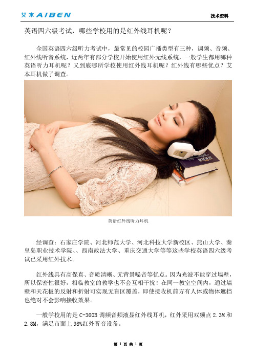
英语四六级考试,哪些学校用的是红外线耳机呢?
技术资料
第 1 页 共 1 页 英语四六级考试,哪些学校用的是红外线耳机呢?
全国英语四六级听力考试中,最常见的校园广播类型有三种,调频、音频、红外线听音系统,近两年有部分学校开始使用红外无线系统,一般学生都用哪种英语听力耳机呢?又到底哪所学校使用红外线耳机呢?红外线有哪些优点?艾本耳机做了调查。
英语红外线听力耳机
经调查:石家庄学院、河北师范大学、河北科技大学新校区、燕山大学、秦皇岛职业技术学院、、西南政法大学、重庆交通大学等等这些学校英语四六级考试已采用红外技术。
红外线具有高保真、音质清晰、无背景噪音等优点。
因为光波不能穿过墙壁,所以保密性很好,相临教室的教学也不会互相干扰!在同一教室空间内,通过墙壁和天花板的反射和折射可实现无盲区覆盖,即使接收机前方有人体或物体遮挡也绝对不会影响接收效果。
一般学校用的是C-360B 调频音频液显红外线耳机,红外采用双频点2.3M 和
2.8M ,满足市面上98%红外听音设备。
DWYER INSTRUMENTS IR3型号红外耳机温度计说明书

The Series IR3 Infrared Thermometer utilizes infrared technology for precise, non-contact temperature measurement. Models feature a 12:1distance to target ratio and single point laser sighting for accurate temperature measurements. The IR3 offers an adjustable emissivity,backlit display, selectable temperature units, high/low alarms, minimum,maximum, differential and average functions.SPECIFICATIONSMeasurement Range:-76 to 932°F (-60 to 500°C).Accuracy:2% of reading or 4°F (2°C) whichever is greater.Emissivity: 0.95 default - adjustable 0.1 + 1.00.Distance to Target: 12:1.Resolution: 0.1°F/0.1°C.Response Time: 1 s.Operating Range: 32 to 122°F (0 to 50°C).Average Battery Life: Typical 180 hours, (2) AAA batteries included.Weight: 3.61 oz (179 g).Dimensions:6.90 x 1.54 x 2.83 in (175.2 x 39.0 x 71.9 mm).OPERATING INSTRUCTIONSSimply aim thermometer at the target and press the “MEAS” key to display the surface temperature.Press “DOWN” key to switch between °F and °C.Hold down the “MEAS” key and “DOWN” key for laser.For Continuous MeasurementPress “UP” key to enter Lock Mode. The lock mode is particularly useful for the continuous monitoring of temperatures for up to 60 minutes.EMISSIVITY:Press “Emissivity” key for setting the emissivity, then press “UP” key or “DOWN” key to set the emissivity, then press “MODE” key to confirm it. The emissivity can be changed from 0.10 (10E) to 1 (100E).Function:Press the “MODE” key for scrolling to display more functions as follows.E:Will show the emissivity data.MAX, MIN DIF,AVG: Press“MODE” keyfor the Maximum (MAX),Difference between MAX and MIN (DIF) and Average (AVG) modes.During the measurement, the special modes reading will be displayed beside the mode icon.HAL, LAL: Press “UP” key or “DOWN” key to change the High Alarm (HAL) or Lo Alarm (LAL) then press “MEAS” key to confirm it.PRB:Connect the thermocouple to the thermocouple socket and put the probe in or on the target to be measured, the thermometer will display the temperature automatically without pressing any button. To see the minimum or maximum data during the probe measurement, please hold down the “UP” key or “DOWN” key.After measuring high temperatures the probe may remain HOT for a while.LED Error MessagesThe thermometer incorporates visual diagnostic messages as follows.“HI/LOW”: “Hi” or “Lo” is displayed when the temperature being measured is outside of the settings of HAL and LAL.“Er2”: Displays when the thermometer is exposed to rapid changes in the ambient temperature.“Er3”:Displays when the ambient temperature exceeds 32°F (0°C) or 122°F (50°C). The thermometer should be allowed plenty of time (minimum 30 minutes) to stabilized to the working/room temperature.For all other error messages it is necessary to reset the thermometer. To reset it, turn the instrument off, remove the battery and wait for a minimum of one minute, reinsert the battery and turn it on. If the error message remains please contact the Dwyer Customer Service department for further assistance.Batteries:The thermometer incorporates visual low battery indication as follows.Battery OK: Measurements are possible.Battery Low: Battery needs to be replaced, measurements are still possible.Battery Exhausted:measurements are not possible. When the low battery icon indicates the battery is low, the batteries should be replaced immediately with AAA, 1.5V batteries.Please Note: It is important to turn the thermometer off before replacing the battery otherwise the thermometer may malfunction. Dispose of used battery promptly and keep away from children.CAUTION1.When device is in use, do not look directly into the laser beam - Permanent eye damage may result.e extreme caution when operating the laser.3.Never point the device towards anyone’s eyes.4.Keep out of reach of all children.EMC/RFIReadings may be affected if the unit is operated within radio frequency electromagnetic field strength of approximately 3 volts per meter, but the performance of the instrument will not be permanently affected. ** Note:under the electromagnetic field of 3V/m from 350 to 550 MHz, the maximum error is 14.4°F (8°C).MAINTENANCEA periodic check of the system calibration is recommended. The Series IR3 is not field serviceable and should be returned if repair is needed (field repair should not be attempted and may void warranty). Be sure to include a brief description of the problem plus any relevant application notes. Contact customer service to receive a return goods authorization number before shipping.Storage and CleaningThe sensor lens is the most delicate part of the thermometer. The lens should be kept clean at all times, care should be taken when cleaning the lens using only a soft cloth or cotton swab with water or medical alcohol.Allowing the lens to fully dry before using the thermometer. Do not submerge any part of the thermometer. The thermometer should be stored at room temperature between -4 and 149ºF (-20 to 65ºC).page 2©Copyright 2014 Dwyer Instruments, Inc.Printed in U.S.A. 5/14FR # R7-443519-01 Rev.2。
红外耳机套件操作手册说明书

Enforcement Technology Group, Inc. (ETGI)400 N. Broadway, 4th waukee, WI 53202Phone: 414‐276‐4471 Fax: 414‐276‐1533Email: Visit: VERSION: ETG ‐IRHPK ‐050112INFRARED (IR) WIRELESS HEADPHONE KIT OPERATING MANUALCOMPONENT LIST:INTROUDUCTION/OVERVIEW:•(4) Dual ‐cup Battery Powered, Wireless Infrared (IR) Monitoring Headphones **•(2) IR Headphone Transmitter Bases Hardwired to 3.5mm (1/8”) “Audio Source Connection”Cable •(2) IR Headphone Transmitter Base Power Adapters•(2) 3.5mm (male) to RCA (female) “Y”Adapters•(2) 3.5mm (female) to 3.5mm (female) Couplers•(2) 12 ft. RCA Composite Audio Extension Cables•(2) 3.5mm (female) to 6.33mm (1/4”) (male) Adapters**Requires (2) AAA Alkaline Batteries (not included).The IR Headphone Transmitter Base is connected to an External Audio Source.The Transmitter Base turns the sounds produced by the External Audio Source into a series of pulses. The pulses work like bits in a computer, digitally capturing the sound information. These pulses are then sent to the Transmitter Base’s infrared (IR) light emitting diode (LED).The LED is a device which produces light at a particular wavelength. The infrared LED produces long wavelength infrared light. It can not be seen with the naked eye, but works much like visible light. It can reflect off of mirrors, for example, and can be blocked by any objects in the way. Because of this, infrared headphones can only be used when they are within a line of sight of the transmitter.The IR Monitoring Headphones are equipped with IR sensors (located on the ear ‐cups) that pick up the light with and turn it back into sound. The IR Monitoring Headphones have an infrared cell, which produces a pulse of electricity every time infrared light lands on it. The cell is designed to pick up the particular frequency of light produced by the Transmitter Base, so it is not disturbed or thrown off by other light. A small computer inside of the headphones takes these pulses of electricity and turns them into an audio signal. This audio signal is then amplified which become audible sound.IR MONITORING HEADPHONE BATTERY INSTALLATION:1.Remove the battery compartment cover located on the right ear ‐cup of the IR Monitoring Headphone. NOTE:A flathead screwdriver may be used to help detach the battery compartment cover from the headphone ear ‐cup.2.Install (2) fresh/new AAA alkaline batteries into the battery compartment according to proper polarity (+/‐). NOTE:When fresh/new AAA alkaline batteries are installed, the device can be powered on/used for approximately 25 hours.3.Replace the battery compartment cover.IR MONITORING HEADPHONETRANSMITTER BASE SET‐UPConnecting the Transmitter Base to an External Power Supply:1.Locate the “Power Adapter”provided with the IR Monitoring Headphone Kit.2.Insert the pin end of the “Power Adapter”into the “DC 12V”power port located on the rear of theTransmitter Base.3.Insert the plug end of the “Power Adapter”into an external power supply outlet.Connecting the Transmitter Base to an External Audio Source:The Transmitter Base can be connected to ANY External Audio Source equipped with one of the following common audio output jacks: 3.5mm (1/8”), 6.33mm (1/4”), or RCA composite.The connection between the Transmitter Base and External Audio Source is facilitated via the “Audio Source Connection”cable that is hardwired to the Transmitter Base.The “Audio Source Connection”cable can be connected directly to an External Audio Source equipped with a 3.5mm (1/8”) audio output jack or indirectly to a 6.33mm (1/4”) or RCA composite audio output jacks via the provided adapters.3.5mm (1/8”) External Audio Source Connection:1.Insert the Transmitter Base’s “Audio Source Connection”cable directly into the External Audio Source’s3.5mm (1/8”) audio output jack.NOTE:The distance between the Transmitter Base and External Audio Source may be increased by using the “3.5mm Coupler”(provided) and longer length of “3.5mm Stereo Cable”(not provided).6.33mm (1/4”) External Audio Source Connection:1.Insert the Transmitter Base’s “Audio Source Connection”cable into the female end of the provided“3.5mm to 6.33mm Adapter.”2.Insert the male end of the “3.5mm to 6.33mm Adapter”into the External Audio Source’s 6.33mm (1/4”)audio output jack.NOTE:The distance between the Transmitter Base and External Audio Source may be increased by using “3.5mm Coupler”(provided) and longer length of “3.5mm Stereo Cable”(not provided).RCA Composite External Audio Source Connection:1.Insert the Transmitter Base’s “Audio Source Connection”cable into a female end of the “3.5mmCoupler”(provided).2.Insert the3.5mm male end of the provided “3.5mm to RCA Y Cable”into the other end of the “3.5mmCoupler.”3.Insert the RCA end(s) of the “3.5mm to RCA Y Cable”into the male ends of the "12 ft. RCA CompositeAudio Extension Cable."4.Insert the other males ends of the "12 ft. RCA Composite Audio Extension Cable" into the External AudioSource’s RCA composite audio output jack(s).IR MONITORING HEADPHONE TRANSMITTER BASE SET ‐UPFor the best audio quality/performance it is strongly recommendthat the Transmitted Base station is set on an elevated surface asthis will help prevent the IR being emitted by the component frombeing blocked.Please note that multiple Transmitter Bases may be used to helpincrease the coverage area of the IR emission.Do NOT place the Transmitter Base in an area that is exposed todirect sunlight or strong light as this may interrupt the soundtransmission.If you use the IR Monitoring Headphones at too great a distancefrom the Transmitter Base, you may hear a hissing noise and ifthere is an object between the headphones and the transmitter,sound may be interrupted. These phenomena are inherent toinfrared ray communication and do NOT mean there is a problemwith the equipment itself.Do NOT cover the IR sensors located on the earcups of the IRMonitoring Headphone with your hands or hair.Infrared (IR) Emission from Transmitter Illustration3.5mm (1/8") Coupler(female) 3.5mm (male) to RCA (female)"Y" Adapter3.5mm (female) to 6.33mm (1/4")(male) Adapter 12 ft. RCA Composite Audio Extension Cable Transmitter Base Positioning:OPERATIONS:1.Power On the Transmitter Base by setting the component’s “POWER ”switch (located on rear) to the “ON ”position.2.Power On the IR Headphone by pressing the devices “ON/OFF ”button (located on bottom of right ear ‐cup). NOTE:The component’s red LED will turn on signaling that the device is on/receiving power .3.Adjust the IR Headphone’s “Volume Control ”dial (located on bottom of left ear ‐cup) until desired listening volume level is achieved.。
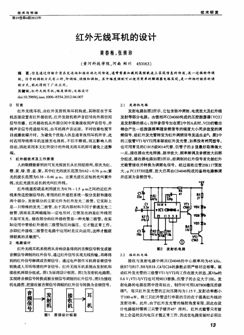
红外无线耳机的设计
置 ,直到伴音信号清晰宏亮 而噪声最小时用高频蜡将磁 帽固
定, 调试 即告完成。如果感觉耳机中的伴音 干涩 、 音质不佳时 , 可适 当调整阻尼 电阻R 6 1 的阻值 ;如果接收器的频带过窄 , 可 以将R 与R1分别开路试试 。 7 7
3 结 语
上磁 帽及屏蔽罩制得。红外发光管与红外光敏管容易损坏 , 它
技 术与 市 场
第 1卷第4 0 2 9 期2 1 年
技 术 研 发
红外 无线耳机 的设计
黄舂梅, 张焕珍
( 河科 技 学 院 , 黄 河南 郑 州
摘
406 ) 5 0 3
要 : 息 通 过 传 输 介 质 在 发 送 端和 接 收 端 之 间 传 送 , 常 需 要 加 栽 到 高频 戢 波 上 实现 信 息 的传 送 , 一 过 程 称 作 调 信 通 这
质量 问题 。
4 结语
时, 这样就具有摩擦桩的作用 。
2 按桩的桩身材料不 同, ) 有灰土桩 、 砂石桩 、 木桩 、 钢桩、 钢
筋混凝土桩。
房屋建筑 中 , 对钻孔灌桩技 术的各项指标要求严格 , 因为 这关 系到房屋 的质 量基础问题 , 所以 , 在工程 实施的过程 中一 定要严格按照 国家的有关规定进行相关 的测量与作业 , 不得 出
无光照 I 0 f ̄_ 5 t E Ok X
基本不受 电磁干扰 , 性价 比高等特点 。电路设 计简单 , 用方 使 便, 在使用音响设备时 , 为不影 响他人学 习和休息 , 可采用这种
无线耳机收听。
参考文献 :
式, 用红外线来传送音频信号 的调幅红外无 线耳机系统 。该系
们 的具体参数如表1 所示 。
红外线耳机工作原理

红外线耳机工作原理
红外线耳机的工作原理是利用红外线无线传输技术进行音频信号的传输。
具体来说,它通过发射器将音频信号转换为红外线信号,然后以无线方式传输到耳机接收器。
发射器中的电路将音频信号转换为适合红外线传输的形式。
然后,它使用红外发射二极管将信号转化为红外线光束,发射到空中。
耳机接收器中的红外接收二极管接收红外线信号,并将其转化为电信号。
接收器的电路将接收到的信号恢复成音频信号,并通过耳机驱动单元将音频输出到耳机的扬声器。
红外线耳机的工作距离较短,因为红外线传输受到光的传播影响,必须有一定的直线传输路径才能有效传输信号。
红外线耳机还需要在发射器和接收器之间保持一定的对准,在传输途中如有阻挡物体,可能会导致传输质量下降。
Voyager 5200 UC 无线耳机系统使用指南说明书

PLANTRONICS + POLYCOM.Voyager 5200 UC無線耳機系統使用指南目錄耳機概觀3充電盒概觀4充電盒連接至 PC 或 USB 轉接器4為耳機充電5檢查電池電量5電量不足警示6使用充電盒7配戴調整888連接與配對9連接至 PC9設定媒體9與行動裝置配對9NFC 配對10重新配對 USB 轉接器10基本功能11撥打/接聽/結束通話11靜音11調整音量11語音助理12啟用並使用 Amazon Alexa12播放或暫停音訊12使用感應器12進階功能15啟用 Tile15語音警示清單15調整語音警示音量15載入軟體16韌體更新17耳機復原17疑難排解18包裝盒內容19配件20規格21支援22充電連接埠通話按鈕Bluetooth 按鈕 (適用於配對裝置時)Siri、Google Now虛擬個人助理 (VPA) 按鈕Alexa**Alexa 需要有 Plantronics Hub 應用程式靜音按鈕音量按鈕指示燈電源按鈕近距離無線通訊耳機概觀USB Bluetooth轉接器收納在充電盒內部。
重要事項充電盒製造完成後,即處於熟睡模式,以節省電力並保護電池。
要喚醒充電盒,請將充電盒插入電源至少 1 分鐘。
充電時,LED 會閃爍。
請先為充電盒充電 90 分鐘,再接上耳機。
充電盒充飽電後到下次連接充電線之間,可為耳機充電兩次,提供高達 14小時的通話時間。
充電盒概觀充電盒連接至 PC 或USB 轉接器您的新耳機在出廠時即具備足夠的電力,可進行配對和幾次通話。
將耳機電池完全充飽大約需要 90 分鐘;充電完成後,指示燈會熄滅。
隨附的 Micro USB 纜線可用來搭配 AC 壁式充電器 (未隨附) 或是透過電腦的 USB 連接埠為耳機充電。
必須將 PC 開機,才能透過 USB 2.0或更高規格進行充電。
或者您也可使用充電盒。
附註一律在溫度接近室溫時充電;切勿在溫度低於 0°C (32°F) 或超過 40°C (104°F) 時為電池充電。
- 1、下载文档前请自行甄别文档内容的完整性,平台不提供额外的编辑、内容补充、找答案等附加服务。
- 2、"仅部分预览"的文档,不可在线预览部分如存在完整性等问题,可反馈申请退款(可完整预览的文档不适用该条件!)。
- 3、如文档侵犯您的权益,请联系客服反馈,我们会尽快为您处理(人工客服工作时间:9:00-18:30)。
成都理工大学电子系统设计------红外耳机学院:核技术与自动化工程学院专业:测控技术与仪器组员:易用环201006010122李茂星201006010102于耀程201006010107指导教师:曾国强吴建平提交日期:2013年6月26日摘要红外线是太阳光线中众多不可见光线中的一种,由德国科学家霍胥尔于1800年发现,又称为红外热辐射。
本系统设计和制作的是一个红外无线耳机,主要通过红外无线耳机的发射电路,使用时将插头插入电视机、收录机或者手机的耳机插座内,音频信号通过经电容Cl耦合、集成芯片放大,再由红外发射二极管向外发射载有音频电波的红外线。
再通过I/V转换,放大,限幅滤波来实现音频信号的提取。
关键词:红外无线接收频率放大滤波目录摘要第一章绪论 (1)1.1 设计背景和意义 (1)1.2 红外耳机的原理 (1)1.3 设计方案 (2)第二章发送部分 (3)2.1 电源电压输入....................................................................................................,,..3 2.2 输入放大部分.. (4)2.3 滤波 (5)2.4 震荡产生90KHZ的锯齿波 (5)2.5 产生占空比不同的方波 (6)2.6 红外发射 (6)第三章接收部分 (6)3.1 I/V转换部分...............................................................................................,.. (6)3.2 放大电路部分 (7)3.3 限幅电路 (8)3.4 滤波部分 (8)3.5 音频输出 (9)第四章焊接 (9)第五章调试 (10)5.1 调试发射的板子 (10)5.2 调试接收的板子 (10)第六章体会与心得 (11)附图 (12)元器件总清单 (15)第一章绪论1.1设计背景和意义我们经常会碰到这样的情况:晚上看电视或听音乐为了不影响家人或者邻居休息,特地使用耳机,却又会常常为耳机线的存在而烦恼,有时是不够长,有时是跟别的设备缠绕在一起,使用起来很不方便。
而今随着电子技术的迅猛发展,无线耳机的制作早已不是一件难事。
无线通讯方式一般来说就是指不需要物理传输线的通讯方式,无线耳机能够免去耳机线的牵扯,与DVD、MP3、电视机,电脑等家电产品配套使用。
它不仅带给我们无拘无束的轻松感觉,更多的是使我们的心情舒畅自在。
因此我们设计了红外无线耳机。
1.2红外耳机的原理红外无线耳机,是以红外线作为通信载体,通过红外光在空中的传播来传输信号,它由红外发射器和红外接收器完成。
在发射端,发射的信号经过幅度调制后,送入电光变换电路,经红外发射管转变为红外光信号发射到空中;在接收端,红外接收器对接收到的红外光信号进行光电变换,幅度解调后恢复出原信号。
图一发射模块结构框图图二接收模块结构框图1.3设计方案无线耳机一般是指以红外线传输信号的耳机系统,红外耳机的工作频率从几KHZ到几MHz,有效距离大约10米,耳机要在可视范围内;无线耳机工作频率为VHF 130MHz-200 MHz、UHF 450 MHz -900MHz,大多数无绳耳机工作在UHF,可传输范围达100米,可以绕过障碍物。
两副或多副无线耳机可能会相互干扰,而且还要注意的是无线耳机电池的使用时间,一般不应低于8小时。
我们这次设计的红外无线耳机共分为两个主要模块:发射模块和接收模块,其中发射电路由输入放大,一阶滤波,二阶滤波,提供90KHz时钟信号电路,积分电路,比较电路和红外发射电路组成。
接收电路由I/V转换电路,放大电路,限幅电路,二阶低通滤波电路与音频输出组成。
要求该电路能够实现无线通讯。
第二章发送部分2.1电源电压输入因为该电路需要稳定的电压源12V,才能达到有声音更清晰。
所以这里选用三端稳压器w7812构成的单电源稳压输出。
2.2输入放大部分主要采用通用型集成功率放大器LM833.LM833是美国国家半导体公司生产的音频功率放大器,具有功耗低、电压增益可调整、电源电压范围大、外接元件少和总谐波失真小等优点,广泛应用于录音机、收音机、对讲机、方波发生器和正弦波振荡器等低电压消费类产品中。
LM833的封装形式有塑封8引线双列直插式和贴片式。
2.3滤波滤波分为一阶滤波和二阶滤波。
LM833和TL072在个部分这里起到的主要是滤波的作用。
2.4震荡产生90KHZ的锯齿波触发器4093B上电后通过芯片4脚震荡产生的180KHZ作用的方波,然后在经过4013B分频到90KHZ,同时4093B又起到缓冲作用,输出的信号在经过和上面的TL072积分器产生90KHZ 的锯齿波。
2.5产生占空比不同的方波输入信号经过放大滤波后,与90KHZ的锯齿波经比较器在图中LM311的7脚产生频率90KHZ占空比不同的方波2.6红外发射产生的方波在经过三极管后由红外二极管发射出来到接收部分。
第三章接收部分3.1 I/V转换部分音频信号的传输电流变化不太稳定,所以要通过LM833把电流转换成电压变换。
这样信号才更稳定。
3.2 放大电路部分选用LM833对接收到的音频信号进行放大,它的优点在上面已有所介绍。
3.3 限幅电路经过对放大信号的幅度限制,就把发送端处理得到的占空比不同的90KHZ方波还原。
3.4 滤波部分将得到的方波信号在经过二阶低通滤波,除去不需要的成分,同时除去噪音,杂质。
3.5 音频输出最后,经过LM386把最原始的声音还原到耳机输出。
LM386是一种音频集成功放,具有自身功耗低、电压增益可调整、电源电压范围大、外接元件少和总谐波失真小等优点,广泛应用于录音机和收音机之中。
第四章焊接在正确雕刻好pcb板子后,打开原理图,仔细比对把相应的器件焊接到板子上。
在焊接时,注意先焊接食物相对较低的、整齐的,如电阻,芯片底座。
由于是自己雕刻的单面板,在画PCB的时候没有把安全距离调的更宽,焊盘大小也不是很大,焊接时尽量注意,不要把雕刻出来的线焊接断了,或则短路的问题。
第五章调试5.1 先调试好发射模块的板子。
5.1.1 在上电开关按下后,立刻出现短路现象,1000uV的电解电容就很快爆炸了,同时7812也很快发烫。
检查电路后,再次把电容焊接好,有给电压,又烧了一个电容。
第三次把线路一次检查,把焊接时留下的多余的焊锡影响到其它模块的挂掉后,再接电路,指示灯亮,电路电压工作正常。
5.1.2 通电后,用万用表测量7812输出电压,约为11.2V,说明电源输入模块是正确的。
5.1.3给输入声音信号出用函数发生器加一正弦信号,声音信号放大后,得到的信号仍然是正弦信号在LM833的7脚测得电压为9.67V 经过滤波后1脚电位和7脚直流电压相同,在经过TL072的1脚是处理后的正弦信号,说明放大,滤波模块也是正确的。
5.1.4触发器产生90KHZ模块的测试。
我们在调试过程中在4093B 的4脚产生的是5.36MHZ的正弦信号。
应该是个180KHZ左右的方波信号。
在仔细检查电路图和PCB图后,同时测量它的14脚电压为11.6V,说明共电压是正常的,没有找到错误。
把其它的芯片拔掉多次调试测量后仍然是一样的结果。
所以可能的错误是整块板子可能有错误,也许这块4093B有问题。
5.2 调试接收的板子。
由于发射的板子都没有调试好,所以接收的板子也没办法调试。
第六章体会与心得在这次电子设计的过程中,我们学到了很多东西。
首先在画电路图时,要仔细,不能有一点错误。
画pcb时,要注意线于线之间安全距离,线的宽度要尽量大点。
无论时雕刻版子,焊接电路,调试过程都要正确,前一个步骤会直接影响到下一个步骤的进行。
要顺利完成“红外无线耳机的设计与制作”这个课题,需要将自身所学知识与设计要求紧密结合,准确地判断出本课题中所包含的各个知识点的要求,并能够利用自身所学有针对性地完成课题研究中各个环节各个阶段的相关任务,举一反三,融会贯通,在认真完成本课题的基础上能有所突破。
进一步加深对相关知识的理解和掌握能力,进一步提高动手操作能力,增强实践技能,使自身素质得到升华。
附图1:发射模块原理图附图2:接收模块原理图附图4:接收模块PCB附图6:•附表:元器件总清单•类型个数备注•LM833 2•4093B 1•4013B 1•TL072 1•LM311 2•LM358 1•LM386 1•BP104 IR 1•7812+12V 1•BC328PNP 1•IR LED 6•GREEN LED 2•IN4004 1电容•2200uf 1 电解16V •1000uf 1 电解25V •470uf 1 电解16V •220uf 3 电解16V •100uf 2 电解16V •47uf 1 电解16V •22uf 1 电解16V •10uf 1 电解16V •220nf 1•100nf 4•100nf 3 陶瓷•47nf 1•10nf 3• 3.3nf 1• 2.2nf 2•1nf 1•680pf 2 陶瓷•470pf 2 陶瓷•180pf 1 陶瓷•100pf 2 陶瓷•15pf 1 陶瓷电阻• 2.2M 3•100k 6•47k 4•22k 4•20k 2•12k 1•10k 2• 5.6k 1• 4.7k 1• 2.4k 1• 2.0k 2•1k 4•390Ω 1•270Ω 1•100Ω 1•47Ω 4•33Ω 2•10Ω 1•50kΩ 1 电位器•10kΩ 1 电位器。