PHILIPS-BDL5588XL-超窄边3×3技术方案
《超窄边液晶拼接屏》课件

总结词
随着超窄边液晶拼接屏技术的不断发展和应用领域的不 断拓展,其市场前景十分广阔。
详细描述
未来,随着超窄边液晶拼接屏技术的不断升级和应用领 域的不断拓展,其市场需求将会持续增长。同时,随着 市场竞争的加剧和技术的不断创新,超窄边液晶拼接屏 的价格也将逐渐降低,进一步推动其在市场上的普及和 应用。因此,超窄边液晶拼接屏的市场前景十分广阔, 有望成为未来显示市场的主流产品之一。
VS
应用领域拓展
随着超窄边液晶拼接屏技术的不断完善和 应用领域的拓展,未来市场将进一步扩大 。除了传统的监控、广告、展示等领域外 ,超窄边液晶拼接屏还将应用于更多新兴 领域,如虚拟现实、智能家居等。这些新 兴领域的发展将为超窄边液晶拼接屏市场 带来新的增长点。
04
超窄边液晶拼接屏的应用案例
商业展示领域的应用案例
竞争策略
各家企业采取不同的竞争策略,有的注重技术创新和产品差异化,有的注重市 场拓展和渠道建设。企业间的竞争合作并存,共同推动超窄边液晶拼接屏市场 的快速发展。
未来市场预测
技术发展
未来几年,超窄边液晶拼接屏技术将继 续升级换代,向着更高分辨率、更低功 耗、更智能化的方向发展。技术的进步 将进一步推动产品性能的提升和成本的 下降,为市场发展提供有力支撑。
THANKS
感谢观看
超窄边液晶拼接屏的发展趋势与未来
展望
技术创新与产品升级
要点一
总结词
随着科技的不断发展,超窄边液晶拼接屏的技术也在不断 进步,未来将会有更多的技术创新和产品升级出现。
要点二
详细描述
超窄边液晶拼接屏的技术创新主要体现在显示效果、拼接 方式、智能化控制等方面。未来,超窄边液晶拼接屏的产 品升级将更加注重用户体验和个性化需求,例如更高的分 辨率、更低的能耗、更智能的拼接方式等。
飞利浦LED显示屏80cm(31.5英寸)边缘LED高清显示 BDL3210Q说明书
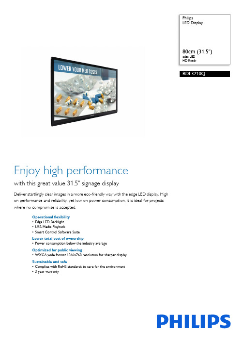
PhilipsLED Displayedge LEDHD ReadyBDL3210QEnjoy high performancewith this great value 31.5" signage displayDeliver startlingly clear images in a more eco-friendly way with the edge LED display. Highon performance and reliability, yet low on power consumption, it is ideal for projectswhere no compromise is accepted.Operational flexibility•Edge LED Backlight•USB Media Playback•Smart Control Software SuiteLower total cost of ownership•Power consumption below the industry averageOptimized for public viewing•WXGA,wide format 1366x768 resolution for sharper displaySustainable and safe•Complies with RoHS standards to care for the environment•3 year warrantyIssue date 2022-04-21Version: 15.3.112 NC: 8670 000 94246EAN: 87 12581 65762 8© 2022 Koninklijke Philips N.V.All Rights reserved.Specifications are subject to change without notice. Trademarks are the property of Koninklijke Philips N.V. or their respective SpecificationsLED Display80cm (31.5") edge LED, HD ReadyHighlightsEdge LED BacklightExperience an even dispersion of light with cutting edge LED technology. White LED's (light emitting diodes) are positioned around the rim of the panel to give a more even spread of light. This results in even lower power consumption, less heat to dissipate, and a true, uniform color range.Compliant with RoHS standardsPhilips designs and produces display products in compliance with strict Restriction of Hazardous Substances (RoHS) standards that restrict lead and other toxic substances that can harm the environment.WXGA 1366x768 resolutionWXGA,wide format 1366x768 resolution for sharper displayUSB PlaybackEnjoy your own media playback via the USB port. Simply plug in a USB drive, and create your own signage content to convey the marketing messages you want, when you want them. With a wide range of media formats supported, this powerful media player offers an excellent picture and true flexibility.Smart ControlControl and manage all of the signage displays on your network with this powerful software tool which allows you to change the settings of your display centrally via an RJ45 or RS232 connection. Smart Control allows you to set the video input, modify the color settings, set the display's ID when creating video walls and even diagnose each display's status, giving you all the power you need to manage your displays from one central location.3 year warrantyEnjoy peace of mind with our comprehensive 3 year warranty. With service centres around the globe, and our quick turnaround, you can be sure that in the most unlikely event of a display malfunctioning, we will find and fix the problem to your fullsatisfaction within the shortest period of time.Picture/Display•Diagonal screen size: 31.5 inch / 80 cm •Panel resolution: 1366 x 768p•Optimum resolution: 1366 x 768 @ 60 Hz •Brightness: 350 cd/m²•Contrast ratio (typical): 1200:1•Response time (typical): 8 ms •Aspect ratio: 16:9•Viewing angle (H / V): 178 / 178 degree •Pixel pitch: 0.17 x 0.51 mm •Display colors: 16.7 Million•Picture enhancement: 3/2 - 2/2 motion pull down, 3D Combfilter, Motion compens. deinterlacing, Progressive scan, 3D MA deinterlacing, Dynamic contrast enhancementSupported Display Resolution•Computer formats Resolution Refresh rate 640 x 480 60, 67, 72, 75Hz 800 x 600 56, 60, 72, 75Hz 1024 x 768 60Hz 1280 x 768 60Hz 1280 x 800 60Hz 1360 x 768 60Hz 1366 x 768 60Hz 1440 x 900 60Hz 1920 x 1080 60Hz •Video formats Resolution Refresh rate 480i 60Hz 480p 60Hz 576p 50Hz 576i 50Hz 720p 50, 60Hz 1080i 50, 60Hz 1080p 50, 60HzConnectivity•PC: VGA-in D-Sub 15HD, RS232 D-Sub9, 3.5 mm PC audio input x1•AV input: HDMI x2, Audio (L/R) x2, Composite RCA x2•Other connections: Component RCA x1•USB: USB 2.0 x 2•AV output: SPDIF Out, Composite RCA x1Convenience•Placement: Landscape•Screen saving functions: Pixel Shift, Low Brightness •Keyboard control: Hidden •Packaging: Reusable box•Network controllable: RS232Dimensions•Set dimensions (W x H x D): 745.2 x 462.7 x 56.8 mm•Bezel thickness: 22mm (45mm bottom)•VESA Mount: 200 x 100 mm •Set weight: 8.05 kg •Set weight (lb): 17.75 lbOperating conditions•Temperature range (operation): 0 - 40 °C•Relative humidity: 20-80 %•MTBF: 50,000 hour(s)Power•Consumption (On mode): 100W •Standby power consumption: <0.5WSound•Built-in speakers: 2 x 10W RMSAccessories•Included accessories: Remote Control, Batteries for remote control, AC Power Cord, VGA cable, User manual on CD-ROM, Quick start guide •Stand: BM03231 (Optional)Miscellaneous•Warranty: Global: 3 years•On-Screen Display Languages: English, French, German, Italian, Polish, Portuguese, Russian, Simplified Chinese, Spanish, Turkish•Regulatory approvals: CE, FCC, Class B, CCC, RoHS, UL/cUL, C-TickMultimedia Applications•Playback Formats: JPEG Still pictures, MP3, MPEG4, AAC LC, AC3, BMP Still pictures, GIF still pictures, M4A, MOV, PNG still pictures, RMVB (RealMedia var. bitrat), WMATechnical specifications•Backlight: Edge LED。
FNbell 2×3 55寸3.5mmLED背光超窄边方案建议书-周总

FNbell液晶拼接系统方案建议书上海峰宁信息科技股份有限公司Feng Ning Information Technology Co.,LTD目录第一章系统概述 (2)第二章需求分析 (3)第三章方案设计 (4)3.1 设计原则 (4)3.2 设计规范 (5)3.3 设计依据 (5)3.4 系统设计 (6)3.4.1 系统组成 (6)3.4.2 设备选型 (6)3.4.3 系统连接 (6)3.4.3 选型设备介绍 (7)3.4.3.1.46寸超窄边液晶拼接屏 (7)3.4.4结构设计 (15)3.5系统功能 ............................................................................................. 错误!未定义书签。
3.6方案实施 (15)3.6.1 安装要求 (15)3.6.2.1.线路敷设及线槽要求 (15)3.6.2.2.空调要求 (15)3.6.2.3.供电电源 (15)3.6.2.4.系统环境 (16)3.6.2.5.布线及接线规则 (16)3.6.2系统安装与验收 (17)3.6.2.1.安装调试 (17)3.6.2.2.验收 (17)3.6.3 系统培训 (18)3.6.4 包装运输方案 (19)3.6.5 工程周期 (20)3.6.7 注意事项 (20)第四章公司简介 (21)4.1 公司介绍 (21)4.1 公司资质 (22)第五章售后服务体系 (22)5.1 售后服务承诺 (22)第六章案例集锦 (23)6.1 案例照片 (23)6.2 案例列表 (37)第一章系统概述随着现代科学技术的发展,图像监控系统的应用范围越来越广,从军事装备的制导、瞄准系统,金融商业的安全监控,公安、交通用的交通监控、监视系统,直到能源矿产、工业用现场监视系统,几乎每一个行业每一个领域都可使用图像监控系统。
超窄3.5英寸双面磁盘驱动器说明书
YD-702J-6637JProduct SpecificationsSUPER SLIM 3.5 FLOPPY DISK DRIVE12.7mm HEIGHT2.0/1.6/1.0 MB 3MODE TYPEFDZ-529022 REV.A4FDZ-529022 REV.A4Revisions Month/ Year RevisionReason for RevisionRevised Pages Oct., 1999Rev. A 1st editionJan., 2000Rev. A1Delete optional connector (NON-ZIF TYPE)P11Apr., 2000Rev. A2Screw fastening torque changeP13Jul., 2001Rev. A3Additional of specification (Non operating shock)P3,4Aug, 2003Rev. A4Added to comments on restrictions of liability and high safety use. Drawing adjustment.P2,12This product specification describes the YD-702J series double-sided, 3.5 floppy disk drive for portable applications.(1) I n this manual, the term “drive” refers to the YD-702J series double-sided,3.5 floppy disk drive. The term “disk” refers to the 3.5 floppy disk.z This specification may be revised without prior notice.Make sure to check the revision number when placing an order.zUnauthorized duplication of this document is prohibited.For the usage of this product for High Safety useThis product is assumed for general uses, such as an object for general office work, personal and home use, and is not designed or manufactured supposing for High safety use. Make sure not to use this product without taking measures to ensure the safety required for the high safety use.High Safety Use means the use that requires extremely high security (see examples), and that accompanies a serious danger for the life and body directly, if security cannot be ensured.*Nuclear control, airplane flight control, air traffic control, mass transportation operation control, life support,weapon launch control, etc.This product specification is subject to change without notice.Chapter 1. IntroductionThese specifications pertain to the YD-702J series of 3.5”, super slim, 5-volt single power supply, double-sided micro floppy disk drives.The YD-702J series has been designed for 3.5 (90mm) floppy disk.1. Super-sliminessWith a 12.7mm height and a weight of 158g, the YD-702J drive is approximately half the size and weight of current 3.5 floppy disk drives (compare with Y-E DATA’s YD-702D).2. Low Power ConsumptionA standard power consumption of 1.15W during operation and 15mW during standby allows for battery-driven operation.3. High PerformanceA direct drive brush less motor is used to guarantee high performance.4. Shock ResistanceShock-absorbing teeth built directly into the head carriage assembly have raised shock resistance to 980.7m/s2 {100G}(11ms half-sine wave)and 2157.5m/s2 {220G}(2ms half-sine wave).FDZ-529022 REV. A4FDZ-529022 REV.A4- 4 -Chapter 2. Product Specifications 2.1 Performance Item 2.0MB Mode 1.6MB Mode 1.0MB Mode Capacityz Unformatted z Formatted 1)Sectors/Track 2)Sectors/Track 3)Sectors/Track Recording Density (bits/mm){BPI}Track Density (tracks/mm){TPI}Cylinders Tracks Encoding Method Rotational Speed (min -1){RPM}Transfer Rate Latency(Average)Access Time z Average z Track to Track z Settling Time z Turn Around Time Motor Start Time2.0Mbytes 18: 1474.6kBytes 686.4{17434}5.315{135}80 Cylinders 160 Tracks MFM 300500 kbits/s 100 ms 94 ms 3 ms 15 ms 4 ms 0.5sec 1.6Mbytes 26: 1025.0kBytes 15: 1182.7kBytes 8: 1261.6kBytes 558.4{14184}5.315{135}77 Cylinders 154 Tracks MFM 360500 kbits/s 83 ms 91 ms 3 ms 15 ms 4 ms 0.5 ms 1.0Mbytes 16: 655.4kBytes 9: 737.3kBytes 5: 819.2kBytes 343.2{8717}5.315{135}80 Cylinders 160 Tracks MFM 300250 kbits/s 100 ms 94 ms 3 ms 15 ms 4 ms 0.5sec Table 2.1 Performance2.2 Physical Specifications 2.3 Reliability and Maintenance MTBF PM*MTTR Component Life Error Rates ●Soft Errors ●Hard Errors ●Seek Errors 30,000POH None 30 minutes 5years or 20,000POH 1 per 109 bits read 1 per 1012 bits read 1 per 106 seek operations Table 2.3 Reliability * Preventive maintenance Note: Non-operating shock and vibration values are the same as above with or without disk in the drive.Signal Connector DC Power Requirements Power Consumption Environment● OperatingTemperature Relative Humidity Maximum Wet Bulb Vibration Shock● Non operatingTemperature storageTransportationRelative HumidityVibrationShockMechanical DimensionsWidthHeightDepthWeightSafety ApprovalsFFC Connector1mm pitch, 26pinIncluding DC power lineRefer to figure 4.2Refer to Table 3.8.1.15W TYP5°C to 50°C (note 1)20% to 80%29°C 9.8m/s 2{1G}(10-200Hz)4.9m/s 2{0.5G}(200-500Hz)58.8m/s 2{6G}(11ms half-sine wave)-40°C to 60°C -40°C to 65°C No condensation 19.6m/s 2{2G}(10-500Hz)980.7m/s 2{100G}(11ms half-sine wave)2157.5m/s 2 {220G}(2ms half-sine wave)96.0mm 12.7mm 130mm 158g(TYP)UL, CSA, TÜV, CE Mounting Recommendations See figure 5.2Table 2.2 Physical SpecificationsNotes:1. Depending on the mounting orientation, drive performance may be affected at maximum temperatures. Please mount the drive to ensure that the temperature at the diskette jacket does not exceed that outlined in the media specifications.FDZ-529022 REV.A4- 5 -Chapter 3. InterfaceRefer to figure 3.6 for all interface connections.3.1 Interface Signals 3.1.1 Input signalsThe YD-702J has input lines as shown below.All lines are active (true) when “Low”(1)(2)(3)(4)(5)(6)(7)(8)DRIVE SELECT 0MOTOR ON DIRECTION SELECT STEP WRITE DATA WRITE GATE SIDE ONE SELECT MODE SELECT Table 3.1 Input Signals 3.1.1.1 DRIVE SELECT 0With the exception of the MOTOR ON signal, all the interface signals become valid when the DRIVE SELECT signal is set to low level.3.1.1.2 MOTOR ONWhen “MOTOR ON” is “Low” and a disk is inserted into the drive, the spindle motor will start. The spindle motor operates regardless of “DRIVE SELECT”. However if the disk is removed, the spindle motor will immediately stop.3.1.1.3 DIRECTION SELECTThis line determines the direction of read/write heads movement when the “STEP” line is pulsed.“HIGH” level Out(away from the center of the disk)“LOW” level In(toward the center of the disk)Table 3.2. DIRECTION SELECTAny change on this line must be done at least 1 usec.before the leading edge of the step pulse, and at least 1 usec. after the trailing edge of the step pulse.Refer to figure 8 for the timing information.3.1.1.4 STEPThis signal moves the read/ write heads in the direction defined by the “DIRECTION SELECT” signal.The access motion is initiated on each “LOW” to “HIGH”level transition, in other words, with the trailing edge of the signal pulse. In a seek operation, an 18 ms delay following the last “STEP” pulse is required for settling time before any read/write operation can be initiated.After direction switching, minimum 4 ms delay is required before initiating the next seek operation.Change of step pulse period during seek operation is not recommended for seek error.Refer to figure 1 for timing.Fig.3.1 Step3.1.1.5 WRITE DATAThe “WRITE DATA” line provides the data to be written on the disk. Each transition from “High” to “Low” onthe line causes the current through the read/ write heads to be reversed, thereby writing a data bit. This line is enabled when the “WRITE GATE” line is “Low” active.Refer to figures 3.2 and 3.11 for the timing information.FM RecordingMFM RecordingFig.3.2 WRITE DATA Notes:1.2.0 / 1.6 MB 1.0MB a 2.00us±10ns 4.00us±20ns b3.00us±15ns 6.00us±30ns c4.00us±20ns 8.00us±40ns d 150-1100ns 150-2100ns2. All timings indicate the values without write pre-compensation.3. The write precompensation value in 2.0MB is 125 ns on all tracks, and in other capacities as below:Capacity 2.0MB 1.6MB 1.0MB WPC value 125 ns 0-125 ns 0-250 ns4. The recommended condition during read operation is to not input “WRITE DATA”.3.1.1.6 WRITE GATEA “Low” active level on this line allows “WRITE DATA” to be written on the disk. A “High” inactive level enables read data logic and stepping logic. Refer to figure 3.11 for the timing information. Activation of “DRIVE SELECT”and “MOTOR ON”, changing “SIDE ONE SELECT” and/or activation of “STEP” must be delayed at least the values indicated (see the following READ RECOVERY TIME table 3.3) following deactivation of “WRITE GATE”because the erase heads remain active during this period.Capacity 2.0MB 1.6MB 1.0MB RRT MIN 650 us 590us 1000 us Table 3.3 Read Recovery TimeC C C Cdca C DDDC ca b dC: Clock D: Data3msMIN1usMINFDZ-529022 REV.A4- 6 -3.1.1.7 SIDE ONE SELECTThis line defines which side of a two sided disk will be used for reading or writing. A “High” level on this line selects the read/write head on side 0 surface on the disk. A “Low”level on this line selects the read/write head on the side 1surface. When switching heads, a 100 usec. delay is required before any read or write operation can be initiated.3.1.1.8 MODE SELECTThe YD-702J series has an internal circuit that performs the switching of the drive’s three (2.0/1.6/1.0MB) capacity modes.Please refer to below.Capacity Mode Switching Method Specifications3 Mode(2.0/1.6/1.0MB)Automatic Switching withInterface SignalThe drive is in 1.0MB mode with double density media and independent of the “MODE SELECT” signal (J1-13).If high-density media is inserted with the “MODE SELECT” signal is “LOW” when the drive is in 1.6MB mode.If high-density media is inserted with the “MODE SELECT” signal is “HIGH” when the drive is in 2.0MB mode.Table 3.4 MODE SELECT Notes:(1)To switch capacity mode is effected by a signal level on the “MODE SELECT” signal.(2)It is necessary to wait 0.5 sec. before executing a read/write operation after motor revolution speed is switched for capacity mode change. :READ DATA”, ”INDEX”, signals are inhibited to output during this term.Fig.3.3 Capacity Mode SwitchingFDZ-529022 REV.A4- 7 -3.1.2 Output signalsOutput signals are shown below. All lines are active when the “DRIVE SELECT” signal is “Low”.(1)TRACK 00(2)INDEX(3)HD(High: HD)(4)WRITE PROTECT (5)READ DATA (6)READY(7)DISK CHANGE Table 3.5 Output Signals 3.1.2.1 TRACK 00A “Low” active level on this line indicates that the read /write heads are positioned at track 00(the outermost track). The line goes “High” inactive when the heads are positioned elsewhere. Refer to Fig.3.8 for the timing information.3.1.2.2 INDEXOne index pulse is output at each revolution of the disk when the drive is ready to read/write. Normally this signal is at “High” level, and makes the transition to “Low” level when a pulse is generated. This signal is inhibited to output during seek and not ready. The controller should detect “INDEX” with the leading edge of the transition rather than with the signal level.Fig.3.4 INDEX3.1.2.3 WRITE PROTECTA “Low” active level on this line indicates that a disk with a write protect notch is loaded. During normal operation the drive will prevent writing when a protected disk has been inserted.3.1.2.4 READ DATAThis line provides the “READ DATA”(clock and data together) as detected by the drive electronics. Normally this signal is “High” level and becomes “Low” level for each flux reversal. The transition from “High” to “Low”level should be used for separation of data bits from read data. This signal is inhibited to output during seek and not ready. The different value between the leading edge of each bit pulse and its nominal position is below note 2.Timing characteristics are shown in figure 3.10.FM RecordingMFM RecordingFig.3.5 READ DATANotes:1.2.0/1.6MB 1.0MBa 2.00us NOM 4.00us NOM.b 3.00us NOM. 6.00us NOM.c 4.00us NOM.8.00us NOM.d 150-1100ns150-2100ns2.Capacity 2.0/1.6MB 1.0MB Difference±350ns±700ns3.1.2.5 DISK CHANGEThe “DISK CHANGE” signal indicates that the disk has been removed. This signal becomes “Low” after power has been applied to the drive and the disk has been removed.This signal remains active until the following conditions have satisfied:(1) A disk is correctly inserted;(2) A drive has been selected and a step pulse has been applied.C D C Cdca C DD D C ca b dC: Clock D: Data(166.7ms ±1.5%)200.0ms ±1.5%1~8msFDZ-529022 REV.A4- 8 -Fig.3.6 Interface Connection 3.1.3 Interface CircuitsThe YD-702J series uses open collector drivers as output line drivers, and TTL level gates as input line receivers.The input of each receiver is terminated in 20 k ohms pulled up to Vcc (+5V). Input/output circuit electrical specifications are as shown below.Inactive “High” Level 2.0 V to Vcc Active “Low” Level 0 to 0.8 V Input Impedance 20 k ohms pulled up to Vcc Table 3.6 Input Circuit Electrical Specifications Inactive “High” Level Open Active“Low” Level0 to 0.4VSink current: 6mA MAXTable 3.7 Output Circuit Electrical SpecificationsThe illustration below shows the recommended controller interface circuit.Fig 3.7 Interface CircuitTo connect the drives to the host system via a daisy chain,an FFC (Flexible Flat Cable) connection cable must be used. Refer to section 4.1.2 for this cable’s specifications.Also, because an FFC cable (as opposed to a conventional flat cable) is used, 2 FFC connectors are required in the host system.Caution: In the case where multiple drivers are connected in a daisy chain, it is forbidden to leave any drive unpowered.Each drive should receive power from the host system.3.1.3.2 Host System Terminal ResistorBecause the line driver of the drive is an open collector output, please use a terminal resistor (1k~5.6k Ω) on the host system side.Cable length 500mm MAXFDZ-529022 REV.A4- 9 -3.1.4 Timing3.1.4.1 Track 00 TimingFig.3.8 Track 00 Timing 3.1.4.2 Seek TimingIn order to reduce the peak current, we recommended that no seek operation be performed for 0.2 secondsafter motor start. Figure 3.9 shows the preferred timing.Fig.3.9 Seek Timing3.1.4.3 Read TimingNote:Capacity 2.0MB 1.6MB 1.0MB X us MIN 650 us 590 us 1000 usFig.3.10 Read Timing 3.1.4.4 Write TimingNote:Capacity 2.0MB 1.6MB 1.0MB X us MIN 650 us 590 us 1000 us Y us MAX4 us 4 us 8 usFig.3.11 Write TimingDIRECTlO STEP TRACK 002.9ms MAX 17us MAXMOTOR ONONDRlVEDIRECTlON SELECTSTEP0.5us MIN 1us MIN1us MIN1us MIN200 ms MIN3 ms MIN4 ms MIN3 ms MINONDRlVEMOTOR ONSTEPSIDE ONEREAD DATA (VALID)WRITE GATE500 ms MAX 18 ms MAX 100us MAX 100us MAXXus MAXVALIDVALIDONDRlVEWRITE GATEWRITE DATAMOTOR ONSTEPSIDE ONE500 ms MIN 18 ms MINYus MAX Yus MAX100us MIN Xus MINXus MINXus MINFDZ-529022 REV.A4- 10 -3.2 Power Interface3.2.1 P ower Supply Specifications VoltageOperating Mode TYP(mA)MAX(mA)Stand by 35Read 230350Write 230350+5VDC ±10%(Ripple: 100 mVp-p MAX)Seek550750Motor Start650740Peak Seek550830Table 3.8 Power Supply SpecificationsNotes:(1) “MAX” values reflect measurement taken at maximum voltage; “TYP” values reflect measurement taken at nominal voltage.(2) “Standby” refers to the state where all input signals are inactive.(3) “Read” and “Write” refer to the state where the heads are at track 40, side 1 and the In Use Lamp is on.(4) “Seek” refers to the average current with the drive continuously seeking at 3 ms and the spindle motor rotating.(5) When the spindle motor starts, “Motor Start” current will continue for approximately 200 ms.(6) Peak current of “Seek” refers to the state of maximum seek current when the spindle motor is rotating and the heads are stepping at 6 ms.The above specifications must be met when voltages are measured at power connector on PWB.3.2.2 C urrent Waveform5 V DC (TYP)MOTOR STARTSTAND BYSTAND BYSEE READ READ WRlTE[mA]1000800600400200Fig.3.12 Current WaveformChapter 4. Physical InterfaceThis drive is connected to the host system by one type of connectors.The cable connections are illustrated in figure4.1 Signal Connector and cable (J1/P1)4.1.1 J1 Signal ConnectorThe J1 Signal connector is 26pin FFC connector located at the rear of the drive.Standard:ZIF TYPE (SMK Model CFP5126-0501 or equivalent)Unit: mm Fig 4.2 J1 Signal Connector Dimensions 4.1.2 P1 CableA P1 cable connector is used to connect the J1 signal connector to the system interface.Recommended PartsFFC: •Sumitomo Electric Industries LTD’s ”sumi”card SMCD-26•Eikura Communication’s ET-C100-264.1.3 Frame GroundThe internal circuit ground on the PWB has beenconnected with the frame for shielding purposes. Theframe ground of the system will be connected to thesignal ground through the drive when the drive isinstalled into the system.The frame ground and signal ground of the systemhave to be connected except the drive.Otherwise the drive ought to be floated from the frameground of the system.4.2 Connector Pin Assignments4.2.1. Signal Connector Pin AssignmentsSignal Pin#Signal name24678910111213141618202224261,3,515~25(Odd No. pins)INDEXDRIVE SELECT 0DISK CHANGEN.C.READYHD (High: HD)MOTOR ONN.C.DIRECTION SELECTMODE SELECTSTEPWRITE DATAWRITE GATETRACK 00WRITE PROTECTREAD DATASIDE ONE SELECT+5VGNDTable 4.1 Signal Connector Pins4.3 TerminatorsAll input lines on the drive are terminated with non-removable resistors of 20k ohms.Hostsystem Drive 0Fig 4.1 Cable ConnectionsDrive 1P1J1P1J1Chapter 5. DiagramsFig.5.1 Mechanical DimensionsRecommended angle of the drive when the drive is installed is less than +30 degrees.Fig.5.2 Recommended Mounting21+/-0.490+/-0.210.91.712.7+/-0.22.5+/-0.2M2.6 tapped holes for installation depth 2.2Max(Each side x2)Eject buttonDisk LED(OPTION)2632.51196+/-0.2126+/-0.4Eject button position5+/-1 (Disk inserted)0.6+/-0.6 (Disk ejected)21+/-0.490+/-0.22.5+/-0.22729.696+/-0.2Signal connector(units:mm)Pin 1insertion32.5NOTES 1) GENERAL TOLERANCES ARE +/-0.596+/-0.2Tapping FaceZ( x4)Z 90.7+/-0.53.6+/-0.53.6+/-0.593.4+/-0.52.6+/-0.53.6+/-0.545.45+/-0.345.45+/-0.396+/-0.221+/-0.42.5+/-0.55+/-0.50+/-0.345.1 Caution on Mounting1)Mounting screws should be tightened by 0.2Nm{2kgf-cm} in torque.2)Mounting bracket is recommended not to make contact with the drive except the mounting spots, and should notbe designed that any portion on the drive except the mounting spots is pressed and/or crushed.3)Recommended to fasten the drive at 3 mounting spots with screws (4 spots available).4)Mounting bracket should be provided structure to absorb strain.5)The drive should be separated or shielded from noise sources. Do not strain the drive. Do not install the drive inlarge electromagnetic fields. Otherwise, failure may result.Not to exceed 5 mm Depth to be at exceed 0.5 mmSide mounting plateSide Mounting(Example 1)FDDFDDFDDThickness not exceed 1 mm Depth to be at exceed 0.5 mmSide mounting plateThickness not exceed 1 mmSide mounting plateThickness not exceed 1 mmFig.5.3 Caution on Mounting Washer dimensionsDiameter not to exceed 5 mm Thickness to be at least 0.5 mmNot to exceed 5 mm Side Mounting(Example 2)Side Mounting(Example 3)5.2 Caution on handling1)Strong vibration and shock can damage the drive. Itmay cause an error. Do not use or store the drive under such conditions.2)We recommend handling the drive on side frame,portion of mounting spots, of the drive as well as possible. If you handle like pressing the top or the bottom of the drive, it may cause damage of heads and PWB.3)Do not disassemble the drive by yourself because ofan adjusted product. If you do so, we can not assure you of adjusted accuracy.Chapter 6. Other Functional Characteristics6.1 Standby ModeThe YD-702J includes standby mode to reduce the load on the host system power supply when the drive is not actually in use. When the spindle motor stops, power to the read/write and spindle motor control systems is cut off, and power to the stepper is cut off when the stepper is not seeking.As a result of this built in power conservation, when all the interface input signals are inactive, typical drive power consumption is 15mW.6.2 In UseThe IN USE lamp will turn on when DRIVE SELECT is at low level and turn off when it is high.6.3 Mask Function“READ DATA” and “INDEX” signals are inhibited to output during seek (includes 18 ms MAX after the last step pulse) and not ready (500 ms MAX after motor start).6.4 Automatic Motor On/OffWhen the disk is inserted or removed, the spindle motor is controlled as follows:1)When the disk is inserted, the spindle motor willstart to rotate regardless of the “MOTOR ON” signal condition. The spindle motor will stop approximately 400 ms later if the “MOTOR ON” signal is not active, but will continue to rotate if it is active.2)When the disk is removed, the spindle motor willstop.。
Philips Signage Solutions Q-Line Display 65 直LED背

Philips Signage Solutions Q-Line Display65"Direct LED Backlight Full HD65BDL3000QIntensify your signage experienceWith priceless performanceDeliver startlingly clear images in a more eco-friendly way with the Q-Line display. High on performance and reliability, yet low on power consumption, it is ideal for projects where no compromise is accepted.Innovative solutions for any signage application •CMND: Take control of your displays•Schedule what you want, when you want with SmartPlayer •Connect and control your content via the cloud with HTML5•Create and update content with CMND & Create Care about you, your business and your audience•Manage settings of multiple displays with CMND & Control •Keep your content up and running with FailOver •SmartPower for energy saving•Simplify meetings with FailOver for conferencing Optimized for public viewing•Full HD LED for brilliant images with incredible contrastHighlightsCMNDA robust display management platform,CMND puts the power back into your hands. Update and manage content with CMND & Create or control your settings with CMND & Control. It's all possible with CMND.CMND & ControlWith CMND & Control, easily managemultiple displays in a central location. With real time display monitoring, setting and software updates from a remote location, and the ability to customize and configure multiple displays at once, such as video wall or menu boarddisplays, controlling your suite of displays has never been easier.SmartPlayerTurn your USB into a true cost effective digital signage device. Simply save your content(video, audio, pictures) on your USB and plug into your display.Create your playlist and schedule your content via the on screen menu,and enjoy your own created playlists anytime, anywhere.FailOverKeeping your content up and running is critical for demanding commercial applications. While it is unlikely you will face a content disaster, FailOver provides content protection with a revolutionary technology that plays back-up content on screen in the event of a media player failure. FailOver automatically kicks in when the primary input fails. Simply select a primary input connection and a FailOver connection and your ready for instant protection.FailOver for Meeting RoomsUsing FailOver, simplify your presentations and videoconferencing. When a meeting or conference room is not in use, background content can run from whatever input source you choose. When the meeting starts and you need to share a presentation or your screen, simply connect your computer and the display automatically switches inputs and shows what'son your screen, with no need to manually switch inputs.Full HD LED technologyPicture Quality matters. Regular displays deliver quality, but you expect more. Imagine crisp detail paired with high brightness, incredible contrast and realistic colors for a true to life picture.SmartBrowserConnect and control your content via the cloud with the integrated HTML5 browser. Design your signage content online andconnect it with a display or with your complete network. Simply plug in a RJ45 internet cable for network connection, connect the display with the dedicated url-address and you are ready to play your cloud based content.CMND & CreateDesign and create compelling content with CMND & Create, a powerful authoring tool. With a drag and drop interface, preloaded templates, and integrated widgets, you'll be able to amaze your customers with compellingcontent.Issue date 2022-07-15Version: 5.1.112 NC: 8670 001 37271EAN: 87 12581 73977 5© 2022 Koninklijke Philips N.V.All Rights reserved.Specifications are subject to change without notice. Trademarks are the property of Koninklijke Philips N.V. or their respective owners.SpecificationsPicture/Display•Diagonal screen size: 65 inch / 163.9 cm •Panel resolution: 1920x1080p•Optimum resolution: 1920 x 1080 @ 60 Hz •Brightness: 350 cd/m²•Contrast ratio (typical): 3000:1•Dynamic contrast ratio: 500,000:1•Response time (typical): 8 ms •Aspect ratio: 16:9•Viewing angle (H / V): 178 / 178 degree •Pixel pitch: 0.74 x 0.74 mm •Display colors: 1.07 Billion•Picture enhancement: 3/2 - 2/2 motion pull down, 3D Combfilter, Motion compens. deinterlacing, Progressive scan, 3D MA deinterlacing, Dynamic contrast enhancement •Panel technology: VASupported Display Resolution•Computer formatsResolutionRefresh rate 640 x 480 60, 67, 72, 75Hz 1024 x 768 60Hz 1280 x 768 60Hz 1280 x 800 60Hz 1360 x 768 60Hz 1600 x 1200 60Hz 1920 x 1080 60Hz 1920 x 1200 60Hz 1280 x 1024 60Hz 720 x 400 70Hz 800 x 600 60, 72, 75Hz •Video formatsResolutionRefresh rate 480p 60Hz 576p 50Hz 720p 50, 60Hz 1080p 50, 60Hz 1080i 25, 30Hz 480i 30, 60Hz 576i 25, 50HzConnectivity•Video input: DVI-D, VGA (Analog D-Sub), USB, Component (BNC), Composite (BNC), DisplayPort (1.2), HDMI (x2)•Audio input: 3.5 mm jack, Audio Left/Right (RCA)•Audio output: Audio Left/Right (RCA), External speaker connector•External control: RS232C (in/out) 2.5 mm jack, IR (in/out) 3.5 mm jack, RJ45•Video output: DisplayPort, DVI-I, VGA (via DVI-D)•Other connections: OPS, USBConvenience•Screen saving functions: Pixel Shift, Low Brightness •Keyboard control: Hidden, Lockable•Network controllable: LAN (RJ45), RS232, One Wire (HDMI-CEC)•Signal loop through: DisplayPort, DVI, VGA, RS232•Ease of installation: Smart Insert•Energy saving functions: Smart Power •Placement: Landscape•Remote control signal: Lockable •Tiled Matrix: Up to 10 x 15Dimensions•Bezel width: 13.9 (Top/Left/Right) 14.9 (Bottom)mm•Set dimensions (W x H x D): 1458.7 x 834.7 x 81.6 mm•Set dimensions in inch (W x H x D): 57.43 x 32.86 x 3.21 inch •Product weight: 24.8 kg •Product weight (lb): 54.7 lb •Wall Mount: 400 x 400 mm, M6•Smart Insert mount: 100 x 100 mm, 100 x 200 mmOperating conditions•Altitude: 0 ~ 3000 m•Temperature range (operation): 0 ~ 40 °C •Temperature range (storage): -20 ~ 60 °C •Relative humidity: 20 ~ 80 %•MTBF: 50,000 hour(s)Power•Mains power: 100 ~ 240 VAC, 50 ~ 60 Hz •Consumption (On mode): 176 W •Standby power consumption: <0.5W •Power Saving Features: Smart PowerSound•Built-in speakers: 2 x 10W RMSAccessories•Included accessories: AC Power Cord, RS232 cable, Remote Control, Batteries for remote control, User manual on CD-ROM, Quick startguide•Optional accessories: Table top standMultimedia Applications•USB Playback Video: M2TS, M4V, MK3D, MKV, MP4, MPEG, MPG, MTS, TS, TTS, VOB, WMV •USB Playback Picture: BMP, GIF, JPEG, JPG•USB Playback Audio: AAC, AIF, AIFF, ASF, M4A, LPCM, M3U, MP3, MP4, WAV, WMAMiscellaneous•Warranty: 3 year warranty•On-Screen Display Languages: Arabic, Simplified Chinese, Traditional Chinese, English, French, German, Italian, Polish, Russian, Spanish, Turkish, Japanese•Regulatory approvals: EPEAT, CE, UL/cUL, CB, GOST, C-Tick, RoHS, FCC, Class B。
液晶拼接显示系统技术方案

超窄边液晶拼接幕墙系统显示方案上海卓飞系统集成有限公司目录目录 (2)第1章前言 (3)第2章方案设计 (4)2.1设计依据 (4)2.2设计原则 (4)2.3LCD的工作原理及特征 (6)2.4主要产品介绍 (7)2.53X4的拼接全屏显示方案 (8)2.6系统显示模式 (10)2.7、拼接单元;包含拼接模块及DID液晶屏、配套电源 (11)第3章系统环境设计和要求 (15)1、安装要求 (15)2、操作控制台(室)装修及设备位置要求 (15)3、光线要求 (15)4、走线及线槽要求 (15)5、空调要求 (16)6、供电电源 (16)7、系统环境 (16)第4章工程案例 (17)处 它 第 1 章 前言随着自动化和信息技术的飞速发展,监控中心对信息显示的要求越来越高,其中大屏幕显示系统作为集中信息显示的交流平台,可以将各种监控系统的计算机图、文信息和视频信号等进行集中显示,在实时调度、会商、决策及信息反馈等方面都起到了重要作用。
随着液晶显示技术、嵌入式硬件拼接技术、多屏图像处理技术、信号切换技术等电视幕墙相关技术的发展,新型液晶拼接幕墙在工程应用的终端大屏幕显示设备中得到迅速普及。
液晶拼接幕墙作为平安城市指挥中心、铁路(地铁)、港口、码头监视系统、智能交通管理监控中心、国防或军事监视系统、电力调度监控系统、大型厂矿监控系统、金融管理监控系统、电视台或大型演播中心监视幕墙、大型演出场所背景幕墙、视频会议等信息汇集、 理的关键显示设备,具有将各类计算机模拟/数字信号、复合视频信号、色差信号等在大屏幕上显示,并实现信号的切换、叠加、组合等功能。
近几年大屏拼接技术也在日新月异的变化,大屏拼接技术也由原来的体积庞大、拼接调试困难像体积轻薄、安装调试简单易用方向发展;由功耗高、辐射高、使用度寿命低向低功耗、无辐射,高寿命方向发展。
随着液晶拼接技术不断地突飞猛进,液晶拼接幕墙的应用领域也更加宽广,性能更加强大,超窄边液晶拼接幕墙全面超越其它显示设备,成为终端大屏显示设备的最佳选择。
Phillips 电动剃须刀 S5588 38 商品说明书
Shaver series 5000SteelPrecision bladesPower Adapt sensor360 D Flexing headsIntegrated pop-up trimmerS5588/38Powerful shave, gentle on skinwith SkinIQ TechnologyThe Philips Series 5000 delivers a powerful shave, cutting now even more hair perstroke*. Equipped with advanced SkinIQ technology, the shaver senses andadapts to your hair density, for improved skin comfort.A powerful shaveMore cutting performance in every strokeFollows the contours of your faceGuides hair into the optimal cutting positionSkinIQ technologyA shaver with the power to tame beardsFor a convenient shaveOne-touch open for easy cleaningChoose a convenient dry or refreshing wet shave5 length settings for versatile beard groomingEven up your moustache and sideburns60 minutes of shaving from a 1 hour chargeFully charged in one hourThe electric shaver with an Eco passportA more intuitive shaving experienceHighlightsSteelPrecision bladesPowerful yet gentle, the 45 self-sharpening SteelPrecision blades on this Philips shaver complete up to 90,000 cutting actions per minute, cutting more hair per stroke** for a clean, comfortable finish.Power Adapt sensorThe electric shaver has an intelligent facial-hair sensor that reads hair density 125 times per second. The technology auto-adapts cutting power for an effortless and gentle shave.360 D Flexing headsDesigned to follow the contours of your face,this Philips electric shaver has fully flexible heads that turn 360° for a thorough and comfortable shave.Hair-Guide precision headsThis new-shape precision shaver is enhanced with hair-guiding channels for optimal cutting and skin comfort.One-touch openClean your electric shaver with the touch of a button. Simply flip open the shaver head and rinse with water.Shave wet or dry A wet and dry shaver that adapts to yourpreference. Choose a convenient dry shave, or pair with your favourite foam or gel for a refreshing wet shave.Pop-up trimmerRefine and define your moustache and sideburns with the pop-up trimmer—and complete your look with ease.Beard styler attachmentWith the choice of 5 different length settings,the beard styler attachment can createanything from the perfect stubble to a short,neatly trimmed beard. It's also useful for a pre-shave trim.60 minutes of cordless shavingA shaver for at home or on-the-go. Get 60 minutes of shaving time from a 1 hour charge or plug it in for instant and continuous power.SpecificationsShaving PerformanceShaving system: SteelPrecision blades Contour following: 360 D Flexing heads SkinIQ technology: Power Adapt sensor Ease of useWet and Dry: Wet and dry useDisplay: LED display, Battery level indicator, Travel lockCleaning: One-touch open, Fully washable DesignHandle: Rubber gripColour: Deep BlackShaving heads: AngularPowerRun time: 60 minutesCharging: 1 hour full charge, 5-min quickchargeAutomatic voltage: 100-240 VStand-by power: 0.04 WMax power consumption: 9 WBattery type: Li-IonService2 year warrantyReplacement head SH71: Replace every 2 yrswith SH71AccessoriesIntegrated pop-up trimmerAttachments: Beard stylerMaintenance: Cleaning brushCharging standTravel and storage: Travel case, Soft pouchNose trimmer includedProtective cap* Tested versus Philips Series 3000.© 2022 Koninklijke Philips N.V.All Rights reserved.Specifications are subject to change without notice. Trademarks are the property of Koninklijke Philips N.V. or their respective owners.Issue date 2022‑03‑30 Version: 4.0.1EAN: 08 71010 39393 20 。
飞利浦 液晶显示器 165 厘米 (65 英寸) 多点触控 全高清 BDL6545AT 说明书
飞利浦液晶显示器多点触控全高清BDL6545AT开创交互新时代带多点触控液晶显示屏使用 165 厘米(65 英寸)全高清液晶显示屏将观众参与推向新的境界。
再借助您自己的触控应用程序,发挥无限潜力!操作灵活•光学触控技术实现高级用户交互体验•开放热插拔规范插槽•度身设计,7 天 24 小时全天候工作•后盖中的智能插入位置可放置小型 PC•通过 RS232 进行远程管理和配置有效降低总拥有成本•用于节能的 SmartPower 技术•高级防图像残留功能可持续发展并且安全•温度传感器衡量设备安全状况•符合 RoHS 标准,关爱环境产品亮点光学多点触控屏幕边缘的传感器可为您带来极致的清晰度,同时提供多点触控,展现各种全新交互应用的可能性。
OPS 插槽开放热插拔规范 (OPS) 插槽面向数字广告市场而开发,设计用于轻而易举地改变或升级您的媒体播放器。
只需将媒体播放器插入显示屏即可。
无论您拥有入门级、中端或高端媒体播放器,OPS 都能完全兼容,为您长期提供较低的 TCO。
SmartPower系统可控制和预设背光强度,节省功耗可高达 50%,从而大大降低了电费。
远程管理:RS232远程管理允许用户通过 RS232 协议远程控制和调节显示器。
使用 CEC 命令,您便可以在您的标牌网络中随时控制所有显示器。
高级防图像残留功能长时间停留在屏幕上的静态图像可能在液晶显示屏上留下“叠影”或产生图像残留效应。
虽然液晶显示屏中的图像残留不会持久存在,但是您需要防止这种现象发生,尤其是在全天候显示内容的场所。
发行日期 2022-04-21版本: 7.3.312 NC: 8670 000 76921EAN: 87 12581 60484 4© 2022 Koninklijke Philips N.V.保留所有权利。
规格如有更改,恕不另行通知。
所有商标是Koninklijke Philips N.V. 或它们各自所有者的财产。
Philips 电视用户手册说明书
Register your product and get support at Smart LED TV /welcome40PFK690940PFK694940PFK695940PFK698940PFS690940PFS690948PFK690948PFK694948PFK695948PFK698948PFS690948PFS690955PFK690955PFK694955PFK695955PFK698955PFS690955PFS6909用户手册内容1 我的全新电视 41.1 Smart TV41.2 应用程序库41.3 租赁视频41.4 社交网络41.5 流光溢彩+hue41.6 Skype51.7 智能手机和平板电脑51.8 暂停电视和录制51.9 游戏51.10 EasyLink52 设置 72.1 阅读安全说明72.2 电视支架和壁挂式安装72.3 安装提示72.4 电源线72.5 天线72.6 卫星天线83 网络∶ 93.1 无线网络93.2 有线网络103.3 网络设置104 连接 124.1 连接提示124.2 EasyLink HDMI CEC134.3 通用接口 - CAM144.4 机顶盒 - STB154.5 卫星接收器154.6 家庭影院系统 - HTS154.7 蓝光光盘播放机174.8 DVD 播放机174.9 游戏控制台174.10 USB 硬盘驱动器184.11 USB 键盘或鼠标184.12 USB 闪存盘194.13 照相机204.14 摄像机204.15 电脑204.16 耳机215 打开 225.1 开机或待机225.2 电视上的按键225.3 字标亮度226 遥控器 236.1 键概述236.2 非 RF 遥控器的红外传感器24 6.3 电池246.4 清洁247 电视频道 257.1 观看电视频道257.2 频道安装298 卫星频道 338.1 观看卫星频道338.2 卫星频道列表338.3 收藏卫星频道338.4 锁定卫星频道348.5 卫星安装358.6 卫星问题389 主菜单 4010 电视指南 4110.1 您需要执行的操作4110.2 使用电视指南4110.3 录音4111 来源 4211.1 来源列表4211.2 从待机模式4211.3 EasyLink4212 定时器和时钟 4312.1 睡眠定时器4312.2 时钟4312.3 关闭定时器4313 3D 4413.1 您需要执行的操作4413.2 3D 眼镜4413.3 3D 眼镜保养4413.4 观看 3D4513.5 优化 3D 观看4513.6 健康警告4514 游戏 4614.1 玩游戏4614.2 双人游戏4615 您的照片、视频和音乐 47 15.1 来自 USB 连接或网络电脑4715.2 Wi-Fi Miracast4816 Pause TV 5017 录制 5117.1 您需要执行的操作5117.2 录制节目5117.3 观看录制5118 Skype 5318.1 关于 Skype5318.2 您需要执行的操作5318.3 开始使用 Skype5318.4 Skype 菜单5418.5 我的个人资料5418.6 员工5418.7 Skype 通话5518.8 Skype 点数5718.9 Skype 设置5718.10 登出5818.11 退出 Skype5818.12 使用条款和隐私政策5819 Smart TV 6019.1 关于 Smart TV6019.2 您需要执行的操作6019.3 设置 Smart TV6019.4 Smart TV 应用程序6019.5 多屏幕视图6219.6 重置 Smart TV6220 Multi room 6320.1 关于 Multi room6320.2 您需要执行的操作6320.3 使用 Multi room6321 设置 6421.1 设置菜单6421.2 画面6521.3 声音6721.4 流光溢彩7021.5 普及使用7222 规格 7422.1 环境7422.2 非卫星电视的接收7422.3 卫星电视的接收7422.4 显示屏7522.5 功率7522.6 尺寸和重量(69x9 系列)75 22.7 连接7622.8 多媒体7623 软件 7723.1 软件更新7723.2 软件版本7723.3 开放源软件7723.4 Open source license7724 故障排除和支持 8424.1 故障检修8424.2 注册8524.3 帮助8524.4 在线帮助8524.5 客户服务/维修8525 安全与维护 8625.1 安全8625.2 屏幕保养8626 用条款、版权和授权 88 26.1 使用条款8826.2 版权和许可88索引 901我的全新电视1.1Smart TV将这台飞利浦智能 LED 电视接入互联网,发现电视的新世界。
mm超窄边大屏拼接技术方案报价
55寸DID(液晶)数字拼接显示系统(3X7)设计方案榆树市英强电脑科技有限公司第一章概述多媒体显示有限公司为此拼接显示墙提供的液晶屏是选用韩国三星电子(sanmsung)生产的55寸DID LCD面板,具有高亮度、高对比度、高像素等特点。
其发热量非常小,以至于站在拼接显示屏前面,也感觉不到它的温升。
液晶独特的显示原理、全数字化的驱动系统,以及自主设计的散热设计方案,确保显示屏的高可靠性和稳定性,同时高强度拼接结构架和美观的外型设计,使拼接显示屏既可靠实用又美观大方。
它将国际最卓越的DID 液晶高清晰度数码显示技术、创博公司的窄边拼接技术、点屏控制器处理技术、信号切换技术、网络技术等的应用综合为一体,形成一个拥有高亮度、高清晰度、高智能化控制、操作方法先进的LCD大屏幕显示系统。
通过这套LCD液晶墙显示系统可以实现对各种系统计算机图像和视频图像信息的综合显示,形成一套功能完善、技术先进的综合信息显示系统,满足客户的各种需要,为显示系统管理提供一个交互式的灵活系统,以适应不断发展的多媒体显示需要。
因此,我们推荐使用目前国际领先的DID液晶拼接显示墙,DID液晶拼接显示墙已经在国内许多重要行业的大屏幕显示应用系统中使用,并得到业界及用户的一致好评!该系统是以DID液晶显示技术为核心的显示子系统,整个系统可与计算机网络系统、视频监控系统和其它独立计算机工作站相联,实现这些计算机图形和视频图像信息的综合显示,满足监控、指挥、调度等各种显示的需要,为用户提供一个直观、交互式的灵活显示系统,以适应不断发展的工作需要。
1.需求分析液晶拼接墙DID(Digital Intelligence Display) LCD是专用的液晶屏。
它是根据应用于安防、广播电视、医疗、工业及公共媒体发布等领域专业监视器的技术要求而设计和生产的,是继NB、PC及TV之后的第四代LCD产品。
以其卓越的显示性能,已经成为人们认同的当前最高端、最理想的液晶监视器显示屏。
- 1、下载文档前请自行甄别文档内容的完整性,平台不提供额外的编辑、内容补充、找答案等附加服务。
- 2、"仅部分预览"的文档,不可在线预览部分如存在完整性等问题,可反馈申请退款(可完整预览的文档不适用该条件!)。
- 3、如文档侵犯您的权益,请联系客服反馈,我们会尽快为您处理(人工客服工作时间:9:00-18:30)。
PHILIPS超窄边液晶显示系统BDL5588XL技术方案书PHILIPS广州市XX信息科技有限公司2015年4月目录第1章概述 (3)1.1 LCD液晶拼接显示墙的应用 (3)1.2 BDL5588XL液晶拼接显示墙技术优势 (3)1.2.1 采用最新液晶面板 (3)1.2.2 超薄窄边箱体单元设计 (4)1.2.3 领先的内置信号处理技术 (4)1.2.4 专业外置拼接控制器 (4)1.2.5 任意的拼接形式 (4)1.2.6 个性化的系统方案 (5)第2章系统设计方案 (6)2.1 系统组成 (6)2.2 显示墙尺寸.................................................. 错误!未定义书签。
2.3 系统结构示意图 (7)2.4 系统显示功能 (8)2.4.1 视频信号显示 (8)2.4.2 计算机和工作站RGB信号显示 (9)2.4.3 网络RGB信号显示 (10)2.4.4 高分辨率图像显示 (10)2.4.5 多种信号混合显示 (11)2.5 系统硬件设备技术规格 (12)2.5.1 BDL5588XL液晶显示单元 (12)第3章工程环境要求 (13)3.1 对供电系统的要求 (13)3.2 对接地系统的要求 (13)3.3 对装修的要求 (13)3.4 对消防系统的要求 (14)3.5 对照明系统的要求 (14)第1章概述1.1LCD液晶拼接显示墙的应用LCD液晶显示屏具有高分辨率、厚度薄、重量轻、低能耗、长寿命、无辐射的优点。
随着窄边框LCD液晶显示屏的出现,使LCD液晶显示屏的无缝拼接成为可能。
LCD液晶拼接显示墙以其高亮度、高清晰度、画面细腻、色彩逼真、画面宏大、视觉冲击力强等特点,具有很好的展示、演示、广告、宣传效果,可广泛应用于广播电视监控及显示,机场、地铁信息发布,金融证券信息显示,政府企业视频会议显示,安全监控系统,商场、酒店、剧院、媒体广告,展览显示系统,品牌专卖店形象展示、演唱会等诸多应用领域,并且安装简便、不受空间限制。
1.2BDL5588XL液晶拼接显示墙技术优势BDL5588XL液晶拼接显示墙系统采用超薄墙体、无缝拼接设计,配以内置信号处理模块、外置图像控制器及控制管理软件,组成一套超高亮度、超高对比度、超高分辨率、高耐用性、高稳定性、超强信号显示能力的拼接显示墙系统,支持视频、RGB、网路信号在拼接显示墙上以单屏、M×N拼接、任意开窗口、任意缩放、跨屏漫游等多种方式显示,可广泛应用于各类以视频图像为主的监控指挥中心、视频会议中心及广告、信息发布等场所。
BDL5588XL液晶拼接显示墙系统具有以下优势:1.2.1采用最新液晶面板系列液晶显示单元采用最新技术的专业液晶面板,具有高亮度、高清晰度、宽色域、亮度均匀、画质优异的特点,亮度达500cd/㎡以上、动态对比度达500000:1以上、色彩饱和度高达92%。
1.2.2超薄窄边箱体单元设计系列液晶显示单元采用超窄边框、超薄箱体设计,以及领先的前维护箱体设计技术,拼接缝隙达到业内领先水平。
BDL5588XL超窄边55英寸液晶显示单元,显示区域之间物理拼缝仅为3.5mm,具有优异的整体显示效果。
1.2.3领先的内置信号处理技术系列液晶显示单元采用具有自主知识产权的内置信号处理技术和拼接处理模块,可提供模拟视频、高清视频、模拟RGB、数字DVI多种信号的接入与显示功能,保证产品应用时具备最大的兼容性和灵活性,无需拼接控制器即可实现M×N拼接,支持信号任意开窗及叠加显示。
1.2.4专业外置拼接控制器图像拼接控制器基于开放式标准工业计算机架构,安全性高、稳定性好,采用最新图形处理及计算机集成技术,独立总线传输技术,多路RGB信号实时并行处理、多路Video信号实时并行处理,支持RGB和Video信号任意混合叠加,支持高分辨率RGB输入。
内部集成切换矩阵和视频总线允许任何视频输入通向任何输出窗口,自动图像识别,支持更多的输入信号,支持本地控制、远程控制、多用户控制。
1.2.5任意的拼接形式BDL5588XL液晶拼接显示墙系统可选择任意M(行)× N(列)拼接形式,可对所有输入信号实现任意位置开窗、单屏显示、组屏显示、跨屏显示、整屏显示、图像叠加、图像缩放、图像漫游等显示方式。
1.2.6个性化的系统方案BDL5588XL液晶拼接显示墙系统可以根据不同用户、不同使用环境的要求进行个性化设计、灵活配置,可依据客户需求提供专业图像控制器、网络信号处理器或内置直通信号处理配置方案,实现满足需求、性价比最高的系统配置及功能。
第2章系统设计方案2.1系统组成本技术书建议采用液晶拼接显示屏结构设计,为节省空间使用前部维护,为液晶拼接显示应用带来了更多的选择。
本技术建议书提供的LCD液晶拼接显示系统由以下部分组成:本项目LCD液晶拼接显示墙由9套46″超窄边显示单元——BDL5588XL组成,组合方式为3×3(行 列);⏹BDL5588XL单屏尺寸:1214mm(宽)×685mm(高) ×104(厚);⏹组合尺寸:3642 mm×2055 mm;⏹底座高度:实际高度根据用户现场确定。
2.2系统结构示意图2.3系统显示功能2.3.1视频信号显示接入图像拼接控制器的视频信号本系统图像控制器处理的输入视频信号可以窗口形式同时显示于大屏幕上。
视频窗口可以实现单屏显示、任意大小显示、跨屏显示、整屏漫游、任意缩放等显示功能,并且可以实现视频图像的分组切换、巡检、预案显示等功能。
通过直通的视频信号显示单元配备1路标准视频输入接口,可以在不依赖外部控制器的情况下直接输入并在组合屏上以屏幕为单位显示视频图像,图像格式支持NTSC/PAL/SECAM 制式。
通过显示屏的内置图像处理模块,直通的复合视频信号除了可以单屏显示以外,还可以M×N方式实现任意多屏拼接显示,及全屏显示。
2.3.2计算机和工作站RGB信号显示经控制器的RGB显示方式本系统图像控制器处理的RGB输入信号可以窗口形式同时显示于大屏幕上。
可以实现单屏显示、任意大小显示、跨屏显示、相互叠加、整屏漫游、任意缩放等显示功能。
直通的RGB显示方式显示单元通过RGB输入接口,可以在不依赖外部图像控制器的情况下直接输入并在组合屏上以屏幕为单位显示计算机RGB图像。
通过显示屏的内置图像处理模块,直通的RGB信号除了可以单屏显示以外,还可以M×N方式实现任意多屏拼接显示及全屏显示。
2.3.3网络RGB信号显示-LCD液晶拼接显示墙系统通过图形拼接控制器的,来自用户局域网中的任意一台用户Windows 计算机/工作站和UNIX 工作站的高分辨率图形信号,都可以窗口的形式在大屏幕上显示出来。
其显示位置、大小、组合方式同样在单一集成操作界面上用鼠标进行控制,也可以实现单屏显示、任意大小显示(无级缩放)、跨屏显示、整屏漫游等。
可实现网络播放视频、PPT动态文件等的实时显示。
2.3.4高分辨率图像显示图像拼接控制器支持高分辨率静态图像及实时GIS、SCADA等直接调用上屏,把全屏作为一个逻辑屏来显示高分辨率的系统应用程序,实现超高分辨率图像显示。
整屏显示分辨率为(1920*3) (1080*3),且整屏的图像无论大小,清晰度不会丧失。
2.3.5多种信号混合显示LCD液晶拼接显示墙系统通过PHILIPS显示单元内置图像处理模块和图像拼接控制器实现灵活多变的拼接处理功能,具有处理计算机RGB信号、视频信号及网络信号的同时显示和不同类型信号混合显示的功能。
2.4系统硬件设备技术规格2.4.1BDL5588XL液晶显示单元第3章工程环境要求3.1对供电系统的要求用户方应在较近的地点提供电源供大屏幕系统接入,空气开关需具备短路,过流及失压保护装置。
为保证显示质量,提供给大屏幕系统电源应尽量使用同一相位。
空气开关至大屏幕系统的电源线和插座等由方负责施工。
大屏幕显示系统所有设备均能在如下条件下正常工作:电压:~220V±10%频率:50Hz±1Hz为了保证大屏幕显示系统显示单元在突然断电情况下不会造成损坏,大屏幕系统建议采用UPS不间断电源供电方式。
3.2对接地系统的要求计算机专用电源采用独立接地,不得与防雷接地共用接地体。
按标准要计算机专用电源电阻不大于2欧姆。
其他接地分为交流工作地、安全保护地、防雷接地体,应小于4 欧姆。
如接地采用综合接地系统,接地电阻按计算机专用接地电阻要求,接地电阻不大于2 欧姆。
用户方应在显示机房设有符合上述要求的接地接入点,并设有明显标示,负责接入点以后与系统的连接。
3.3对装修的要求机房地面最好使用防静电地板,或其它不反光的地面材料。
大屏幕下方不使用防静电地板,显示屏底座需直接安装和固定在混凝土地面上。
作为显示窗口的装修墙,墙体要求牢靠,墙体结构件不得受力于大屏幕系统,显示墙窗口四周平直不变形,窗口尺寸比显示墙屏幕大40-60mm,即比显示墙屏幕每边大出20-30mm,以方便显示墙安装。
3.4对消防系统的要求消防喷头要远离显示屏体1米左右,并且不得使用自动喷水喷淋头,宜采用干粉灭火剂。
3.5对照明系统的要求显示屏前面2米内为暗区,可安装内藏式筒灯,平行于显示屏排列,并设有单独的可控开关。
灯光不能直接照射到显示屏上,并且尽量不要使用荧光灯。
整个显示控制中心的灯按平行于显示屏方向分组进行控制,不宜选用较强光源。
对于显示控制中心可能射入的户外光线(如窗户),应有必要的遮挡措施(如安装深色窗帘)。